




Power Semiconductor Devices and AC-DC Converters is a reliably scoring topic in GATE Electrical, usually worth about 5 to 8 marks in the paper. It belongs to the Measurements and Electronics section, and its ideas return in electric drives, DC-DC choppers, and inverter circuits. These handwritten notes cover the full topic in a compact, exam-focused form.
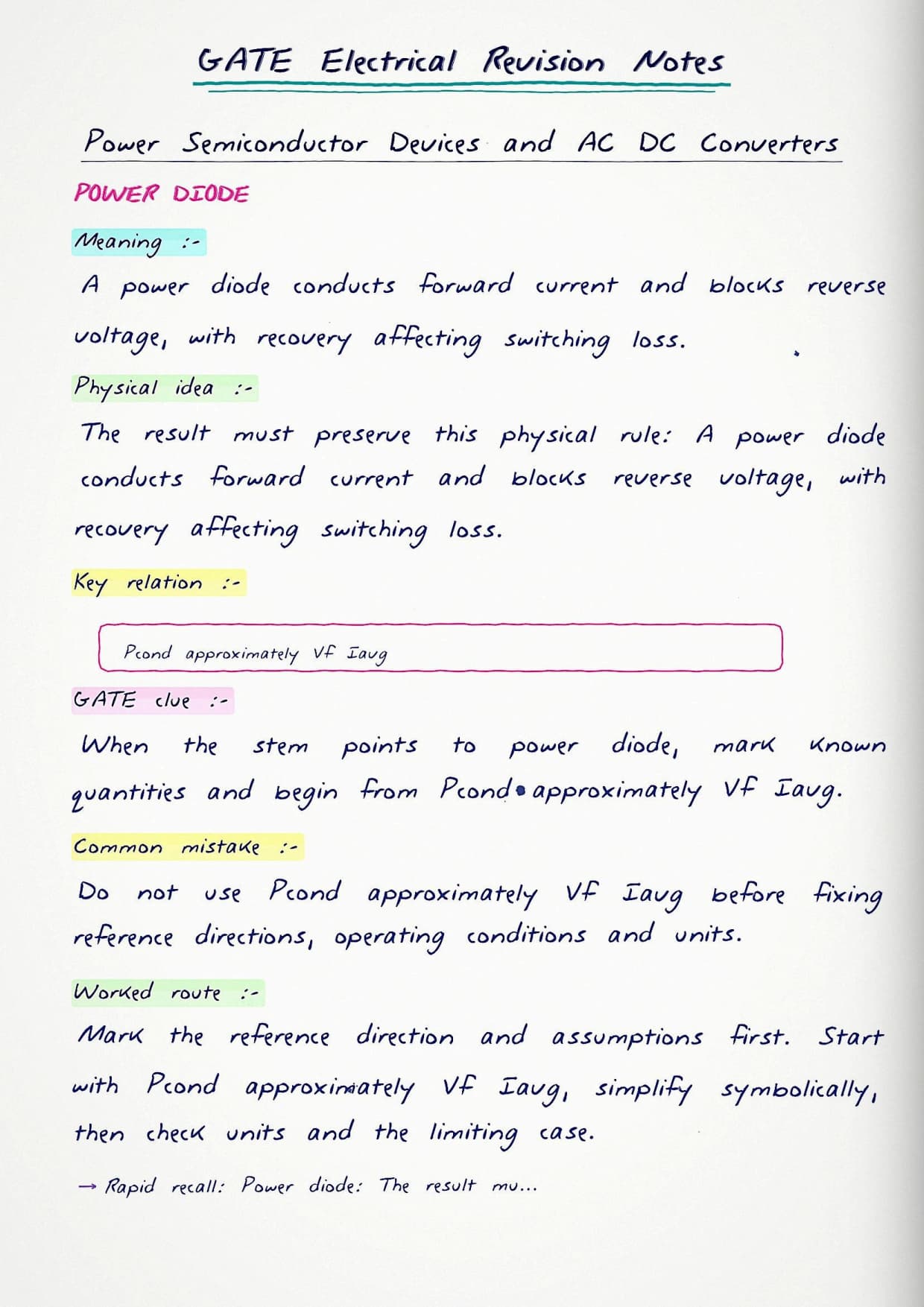
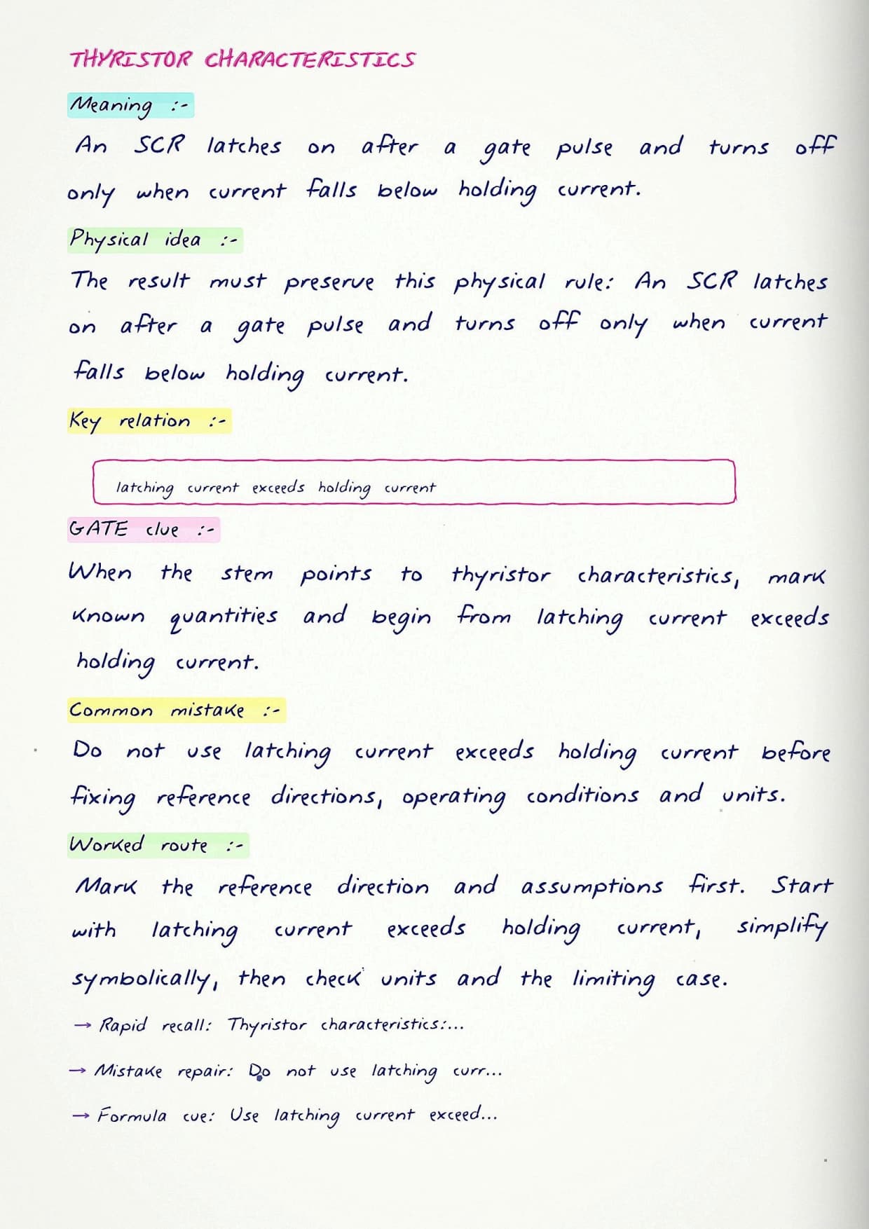
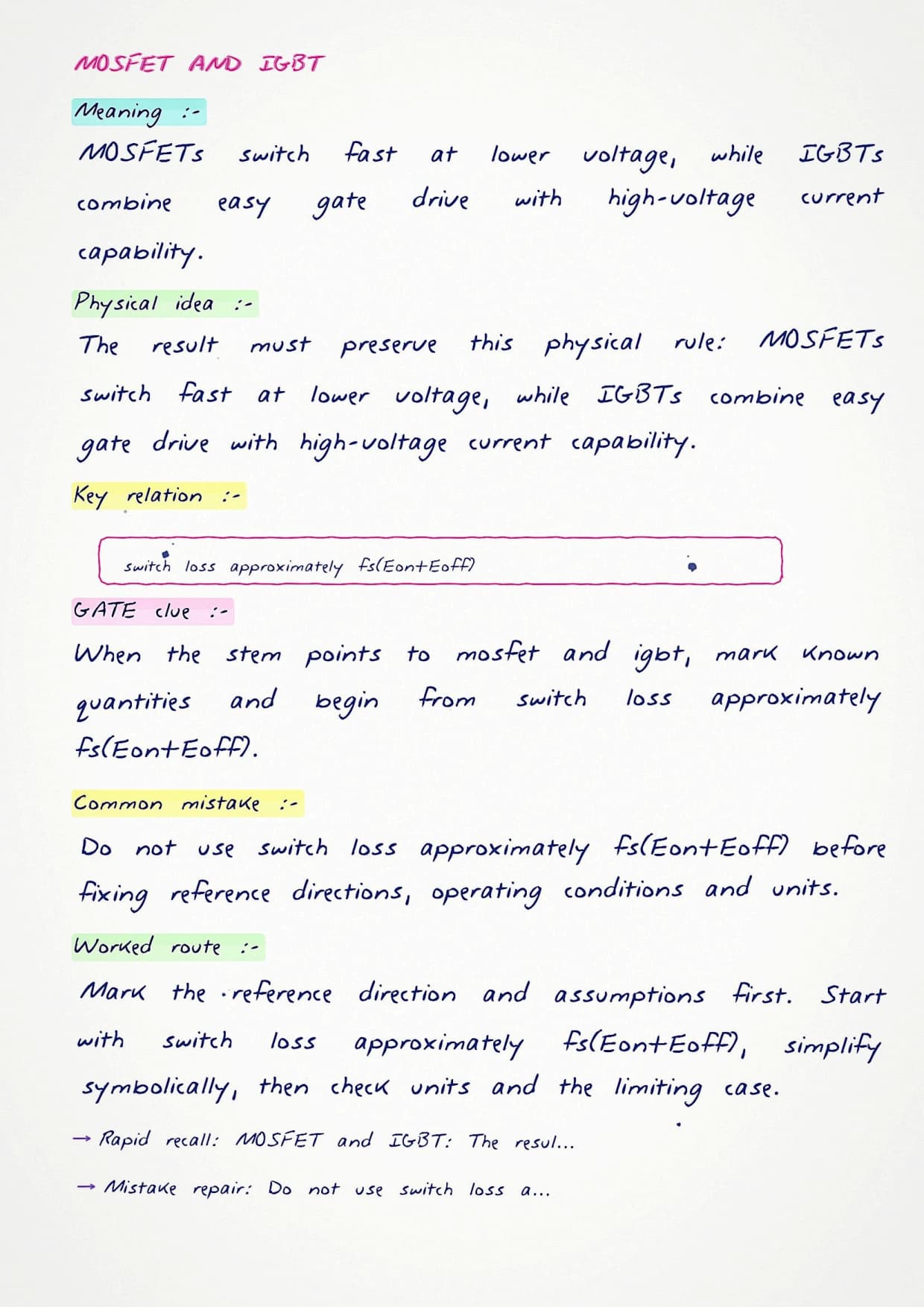
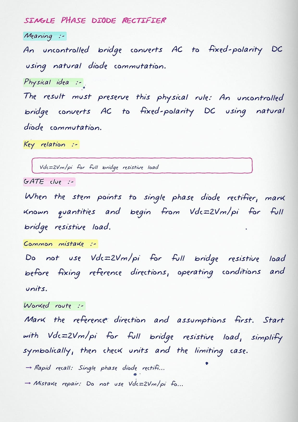
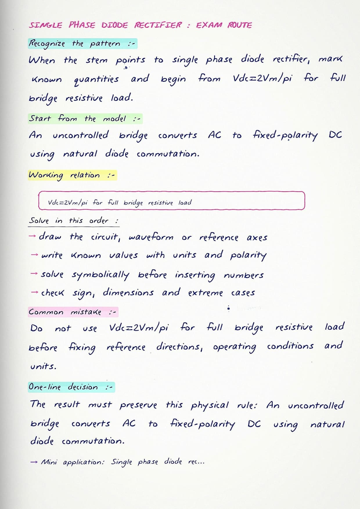
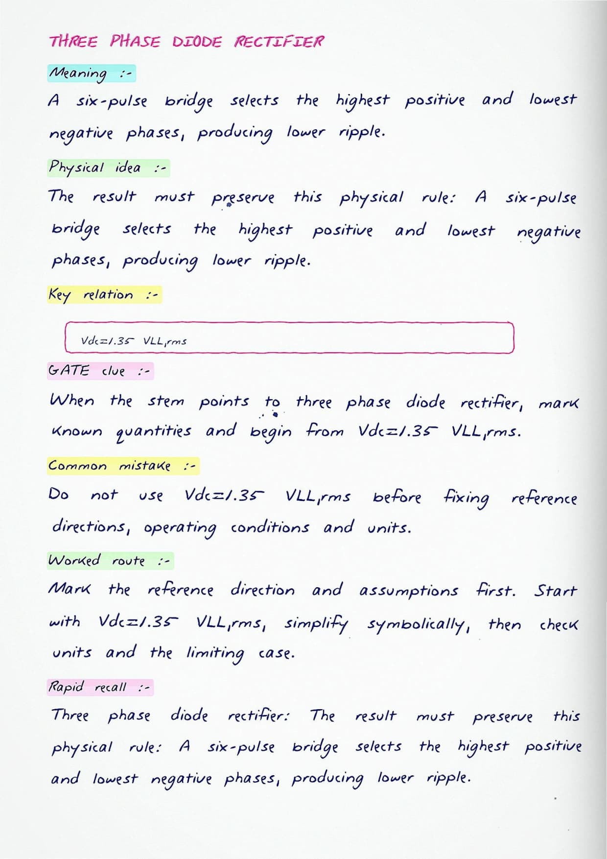
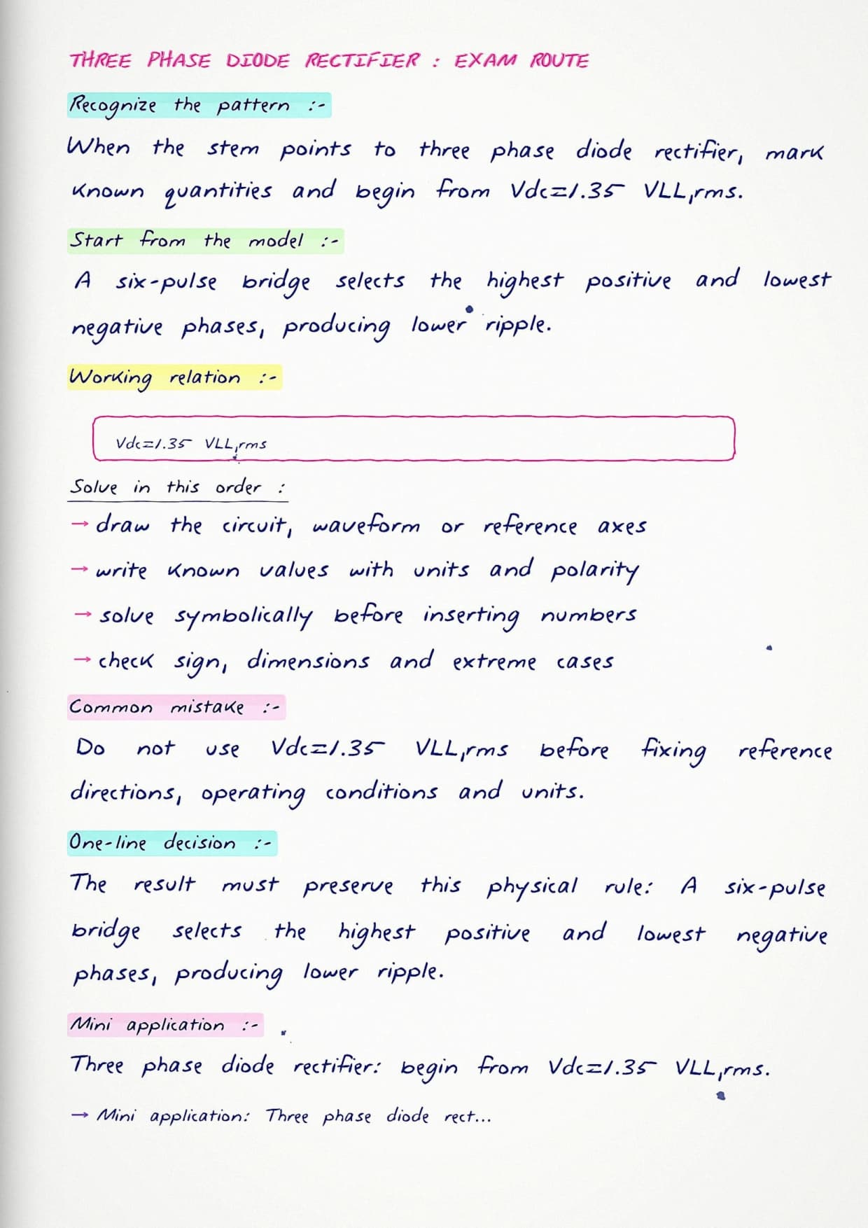
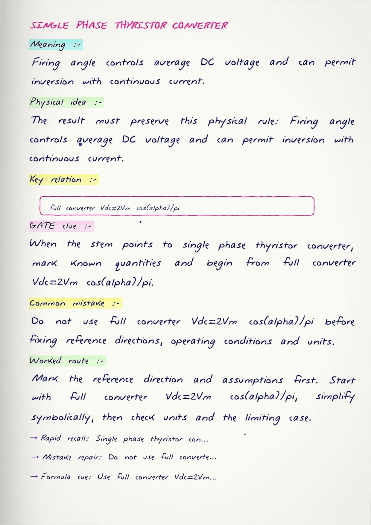
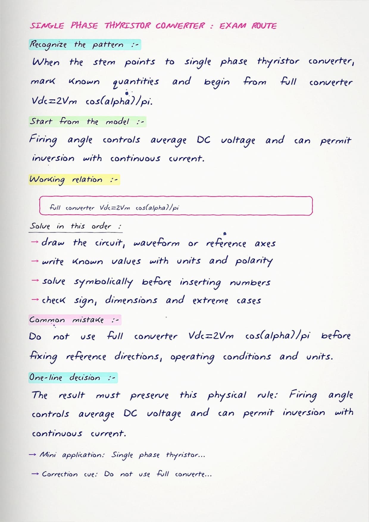
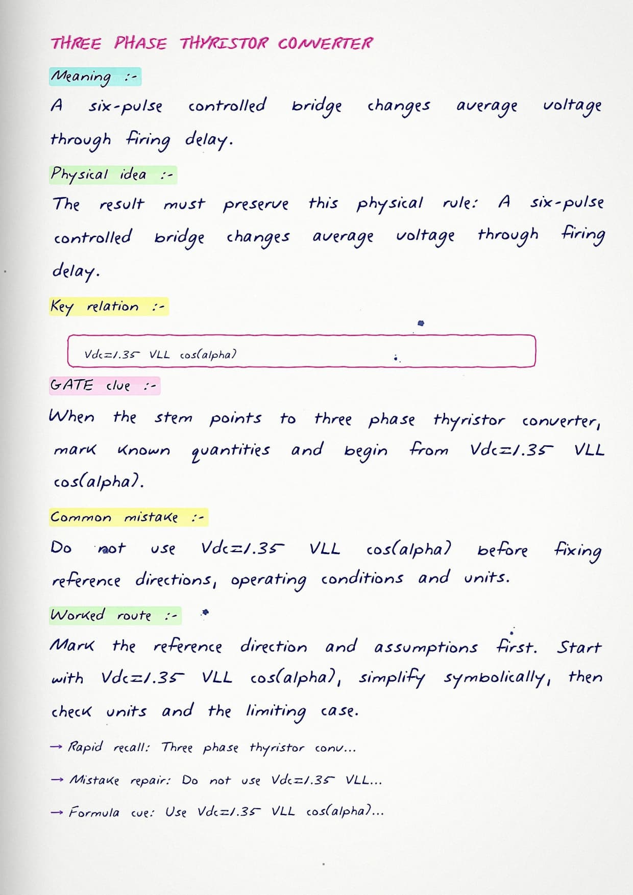
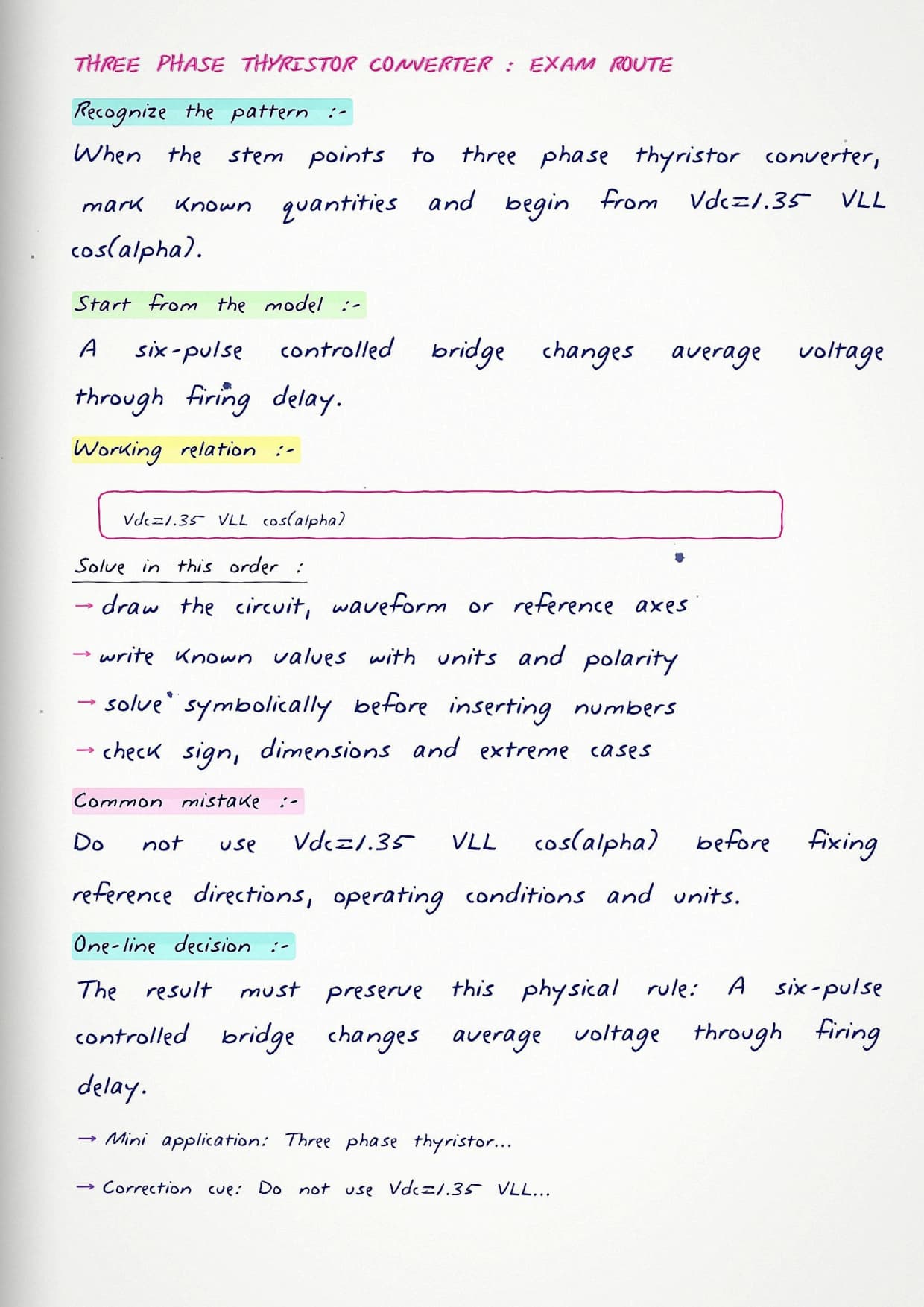
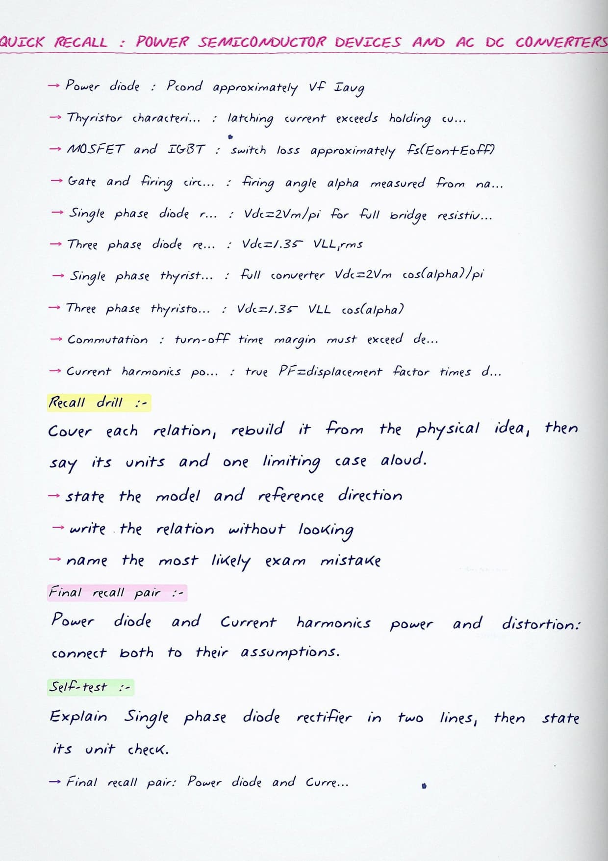
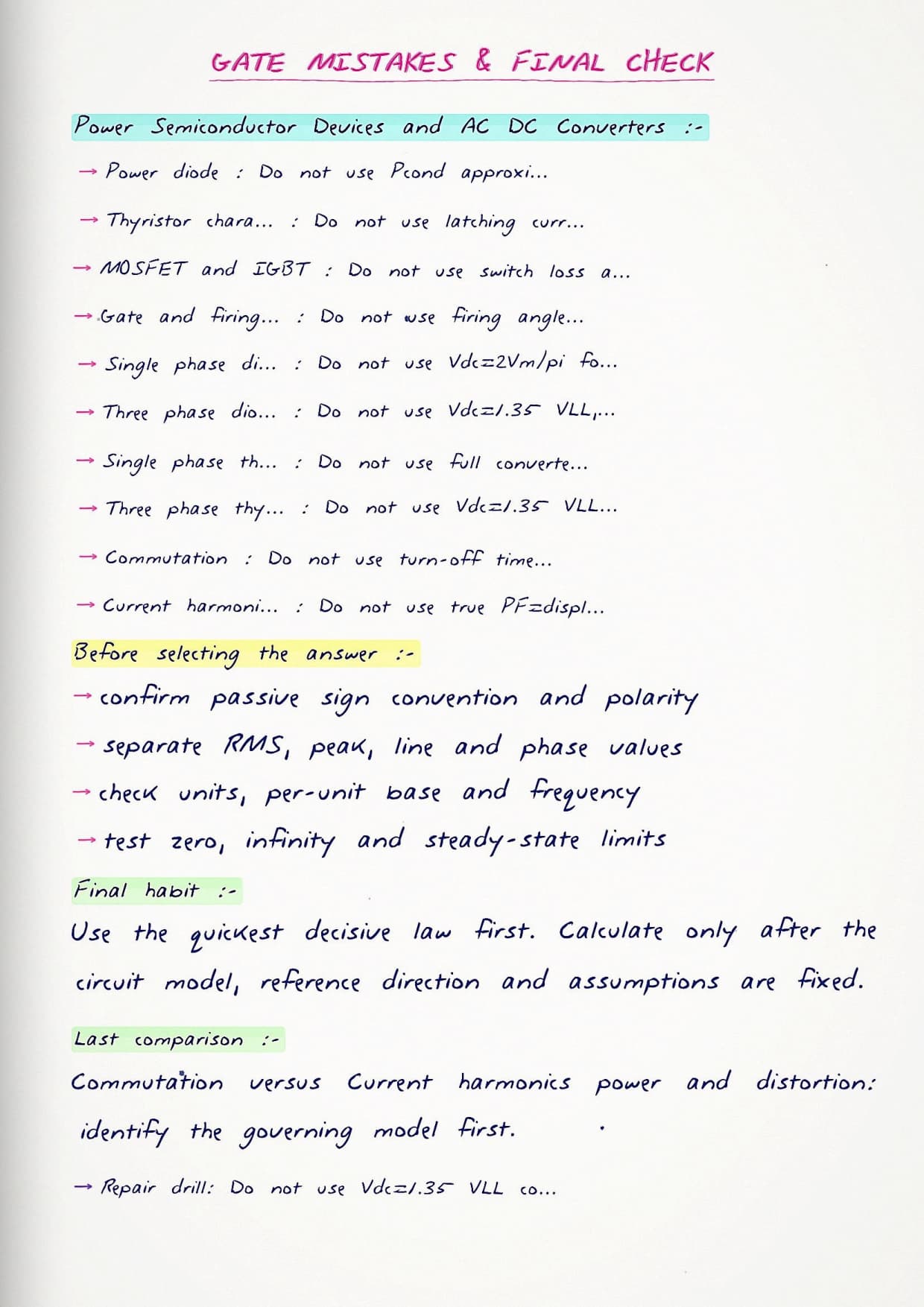
The pages open with clear device symbols and their layer structure, so students can tell a thyristor from an IGBT at a glance. Each converter is drawn as a full circuit with the conducting devices shaded for one cycle, and the output voltage waveform is sketched right below it. A short formula sheet gathers the average output and ripple results for every rectifier the syllabus names.
- Layer sketches and switching characteristics of the diode, thyristor, MOSFET, and IGBT side by side.
- Full circuit drawings of single-phase and three-phase rectifiers with the firing angle marked.
- Neat output waveforms under resistive and inductive loads, with the average value worked out beneath each one.
What These GATE Power Electronics Notes Cover
The notes take students from the physics of a power switch to the behaviour of a full converter feeding a real load. Every device and every circuit is drawn, so the ideas stay concrete rather than abstract. The focus stays on what the exam rewards, namely reading a circuit, marking the conducting device, and pulling the average output straight from the waveform.
- Structure, symbol, and ratings of the main power semiconductor devices.
- Turn-on and turn-off behaviour, including thyristor triggering and commutation.
- Uncontrolled and controlled rectifiers in single-phase and three-phase forms.
- Effect of load type and firing angle on the output voltage and current.
GATE Power Electronics Quick Revision
Source: Genique Education on YouTube
Topics Covered in GATE Power Electronics
The coverage follows the official GATE Electrical syllabus for power semiconductor devices and AC-DC conversion. Each point below has a worked page so students can go straight to the converter they find hardest.
- Characteristics of the power diode, thyristor, TRIAC, GTO, MOSFET, and IGBT.
- Thyristor gate triggering, latching current, and holding current.
- Single-phase half-wave and full-wave uncontrolled rectifiers.
- Single-phase controlled rectifiers with resistive and highly inductive loads.
- Three-phase bridge rectifiers and their average output voltage.
- Line commutation, freewheeling diode action, and output ripple.
- Input power factor and harmonics drawn by phase-controlled converters.
How the Notes Are Organised
The order builds a converter from the ground up. Students first meet the single switch and how it turns on and off, then see those switches assembled into a rectifier, and finally read how the load and firing angle shape the output. This layering means a hard converter never arrives before the device that runs it has been understood.
Each rectifier gets its own page with circuit, waveform, and result stacked together, so nothing has to be flipped between. The closing sheet lists every average-voltage formula in one place for fast recall before the exam.
How GATE Power Electronics Links to Other Topics
Converters do not work in isolation; they feed machines and share devices with other circuits. A solid grip on this topic opens up much of the rest of the electronics and drives syllabus.
- DC-DC choppers, which reuse the same switching devices in a different arrangement.
- Inverters, where controlled switches build an AC output from a DC supply.
- Electric drives, which use rectifiers to feed DC and AC motors.
- Analog electronics, where the diode and transistor basics first appear.
Important Topics in GATE Power Electronics
A few converter results appear again and again, and each carries a classic trap. The notes flag these so students keep the marks that careless waveform reading often loses.
- Getting the average output voltage right for each firing angle and load type.
- Knowing when a freewheeling diode changes the conduction and the output.
- Telling apart continuous and discontinuous current with inductive loads.
- Reading the device ratings, since peak voltage and current decide the choice.
- Handling the input power factor, which drops as the firing angle grows.
How to Prepare GATE Power Electronics with Handwritten Notes
This topic is won on clean circuit reading and steady waveform practice. Students should learn each device once, then drill the rectifier waveforms until the average value comes fast. The plan below fits that rhythm.
- First read: copy each device symbol and note its turn-on and turn-off rule.
- Second pass: redraw one rectifier waveform and derive its average voltage.
- PYQ practice: solve past GATE Electrical questions on controlled rectifiers.
- Final week: revise the device table and the average-voltage formula sheet.
Why These Notes Help You Score Better
Power electronics questions turn on reading a circuit and its waveform correctly, and these notes train exactly that skill. The shaded conduction paths make each converter obvious, the stacked waveforms build speed, and the flagged traps protect the easy marks. Because the device table and the rectifier results sit in one place, a student can rebuild the whole topic quickly on the day before the exam. Revised across a full cycle, these notes leave students ready to convert this section into a dependable score.
GATE Electrical Power Electronics Handwritten Notes FAQs
Ques. How many marks do power devices and AC-DC converters carry in GATE Electrical?
Ans. The topic usually contributes about 5 to 8 marks from the Measurements and Electronics section, making it a dependable scoring area for students who master the converter waveforms.
Ques. Do the notes show converter circuits and waveforms together?
Ans. Yes. Each rectifier is drawn as a full circuit with the conducting devices shaded, and its output waveform is sketched right below, so students see the cause and the result on one page.
Ques. Are all the main power devices covered?
Ans. Yes. The notes include the power diode, thyristor, TRIAC, GTO, MOSFET, and IGBT, with their symbols, layer structure, and switching behaviour placed side by side for easy comparison.
Ques. Which mistake costs students the most marks here?
Ans. Misreading the output waveform when a freewheeling diode or an inductive load is present is the common slip. The notes flag these cases so students compute the average voltage correctly.



Comments