




DC-DC Converters, Inverters and Sinusoidal PWM is a heavily tested area in GATE Electrical, usually worth about 5 to 8 marks in the paper. It falls under the Measurements and Electronics group of the syllabus, and its ideas return in rectifiers and AC-DC converters, power semiconductor devices, and electric drives. These handwritten notes cover the full topic in a compact, exam-focused form.
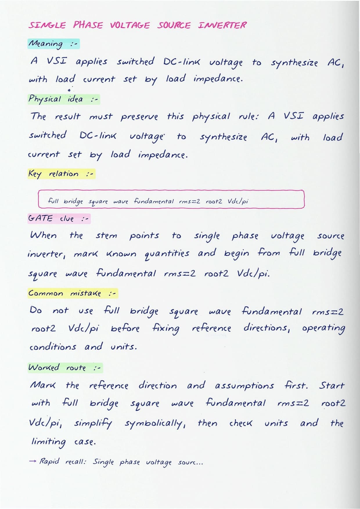
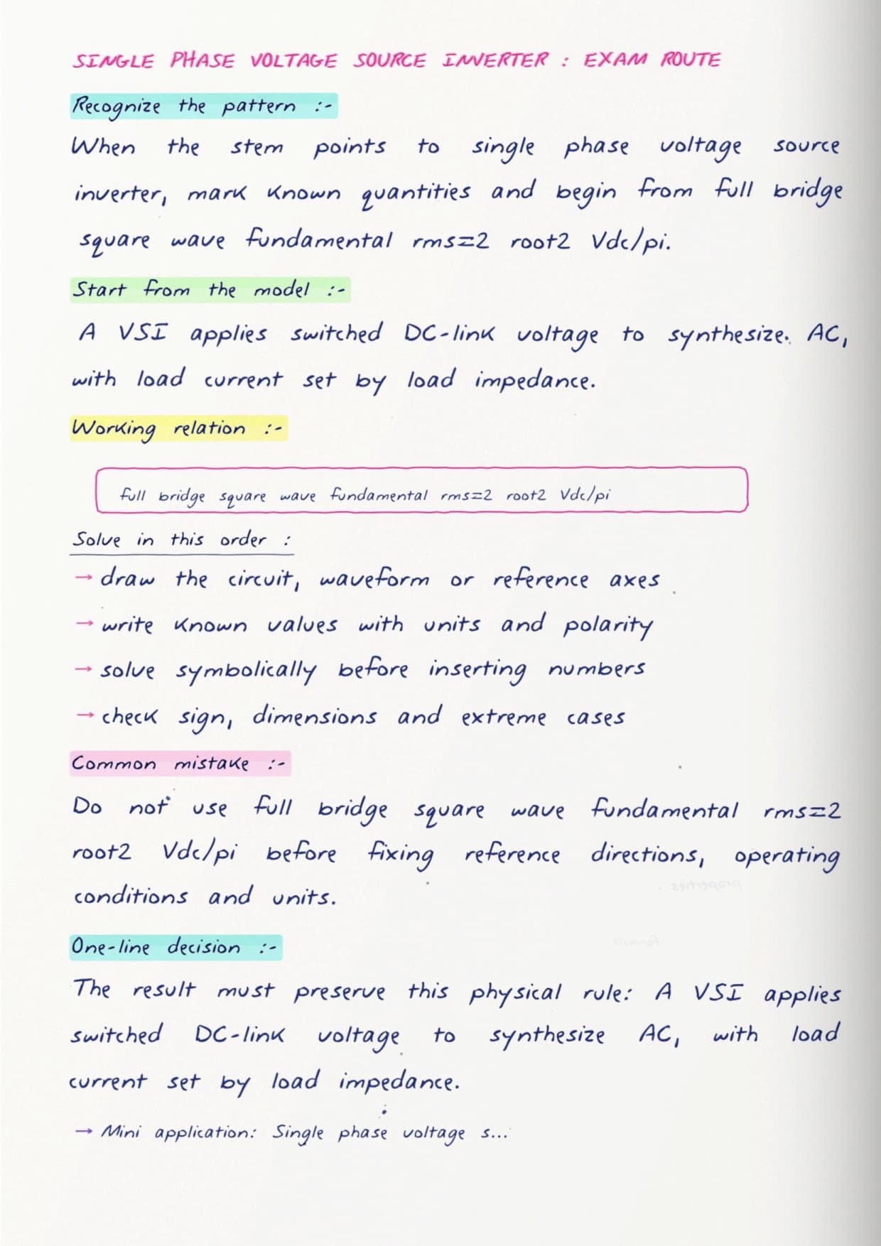
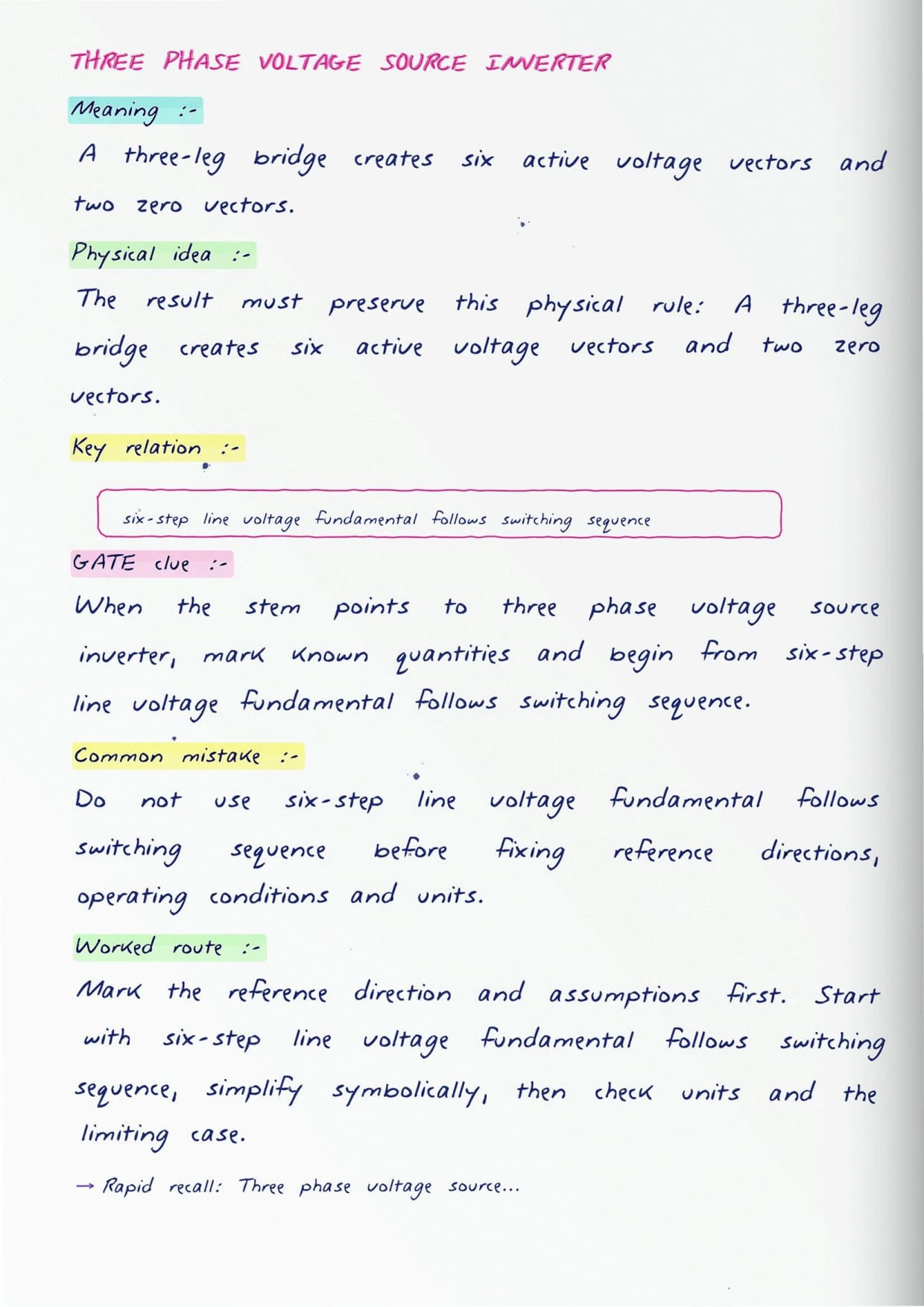
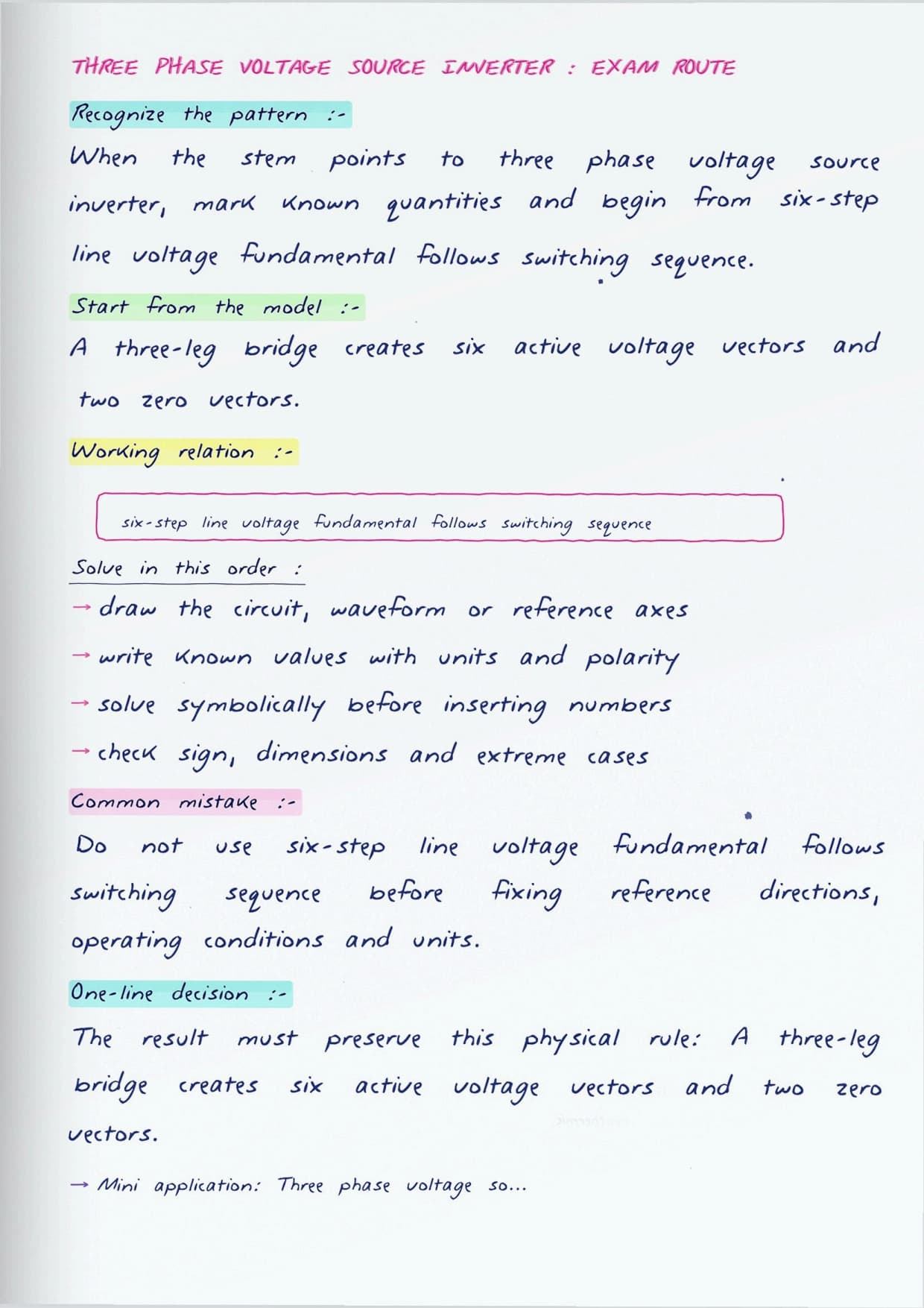
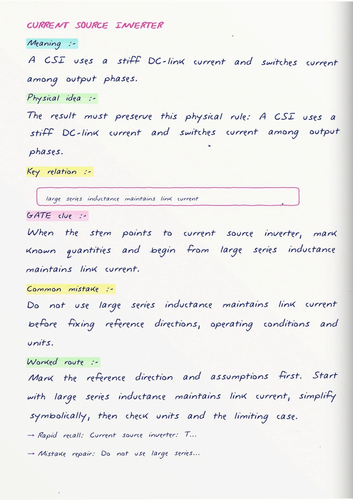
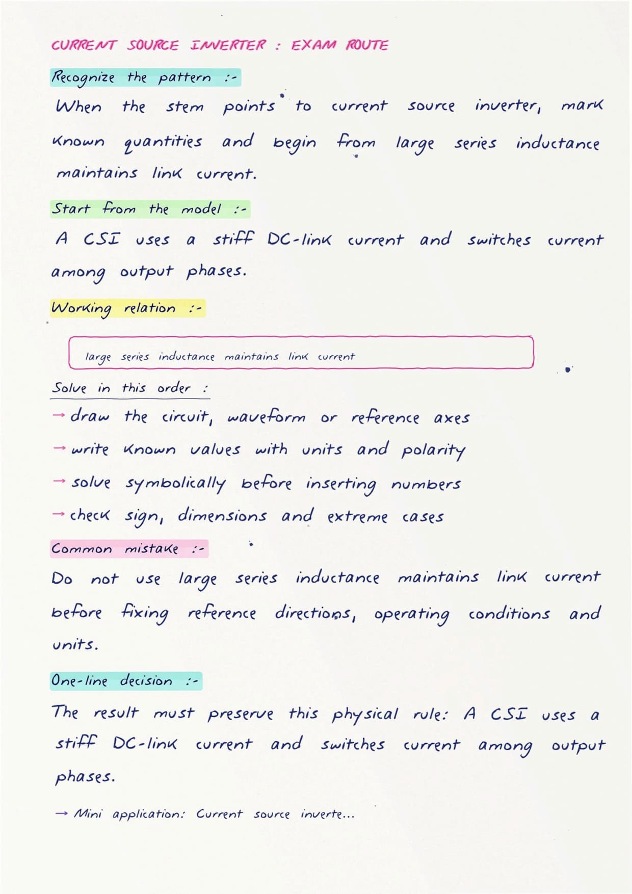
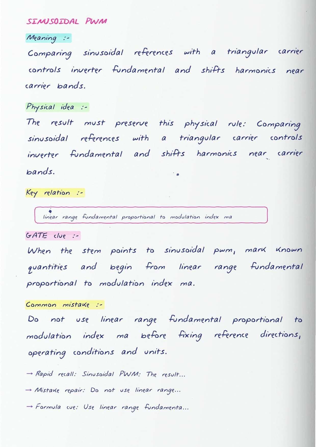
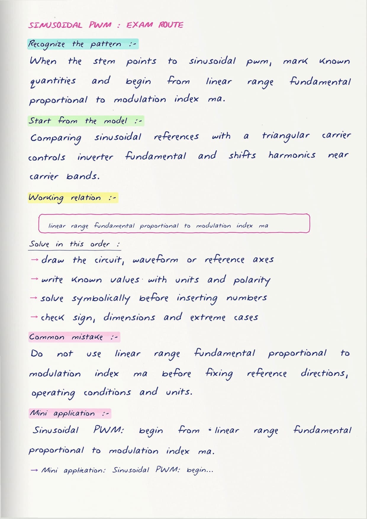
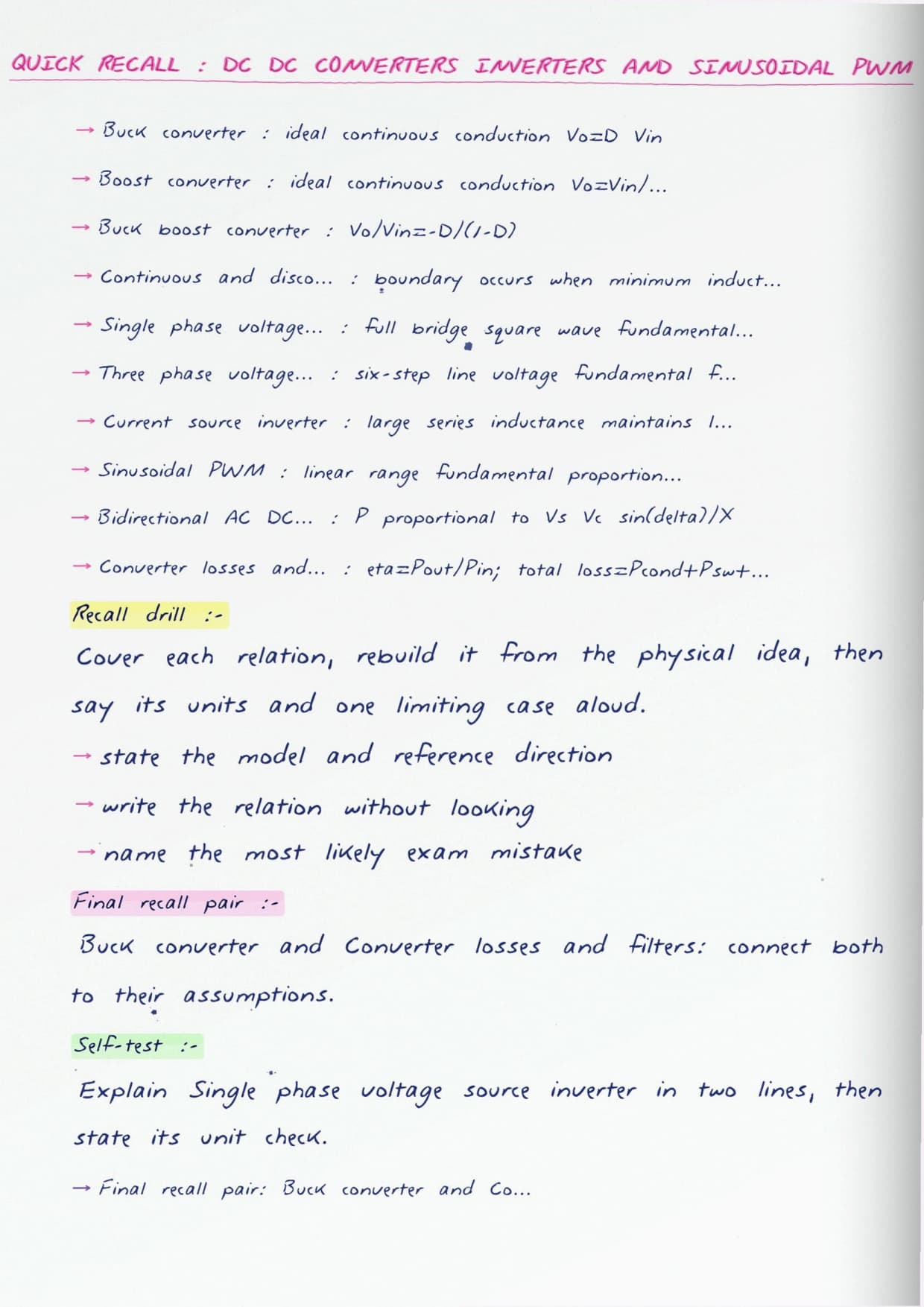
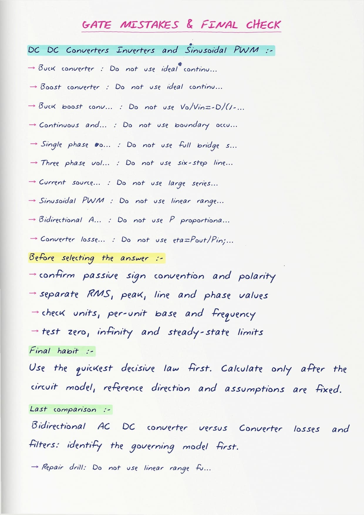
The notes lead with clean switching waveforms drawn by hand, so students can see the inductor current build and decay in a chopper before meeting the duty ratio formula. A labelled buck, boost, and buck-boost page compares output voltages at a glance, while a single-phase bridge inverter sketch shows how the sinusoidal reference and triangular carrier cross to set each pulse width. The switch numbering is drawn in beside every waveform, so students can see exactly which pair conducts in each interval and never lose track during a longer bridge problem.
- Waveform-first pages for step-down and step-up choppers with average-voltage working.
- A side-by-side sheet on square-wave and PWM inverters and their harmonic content.
- Clear notes on the modulation index and how it fixes the fundamental output.
What These GATE DC-DC Converters and Inverters Notes Cover
These pages run from the basic switching cell to a full sinusoidal-PWM inverter. The focus stays on the waveforms and the few formulas GATE tests, so students can answer quickly without heavy derivation. A short opener on the ideal switch and the inductor volt-second balance sets up every result that follows, since both ideas repeat in every converter on the sheet.
- Buck, boost, and buck-boost converters in continuous conduction.
- Chopper control by duty ratio, and current ripple limits.
- Single-phase and three-phase inverters in square-wave mode.
- Sinusoidal PWM, modulation index, and output harmonic behaviour.
GATE DC-DC Converters and Inverters Quick Revision
Source: GATE Wallah CSE & DA on YouTube
Topics Covered in GATE DC-DC Converters and Inverters
The list matches the official GATE Electrical power-electronics syllabus for converters and inverters. Each entry appears with a short worked case so students can tie a waveform to a number.
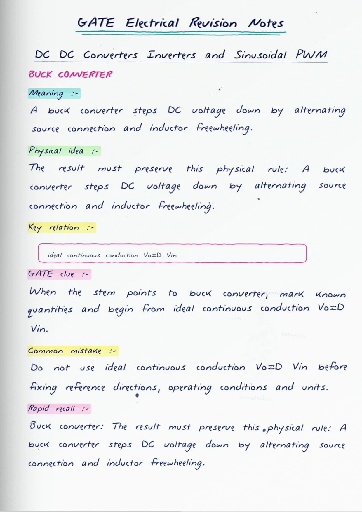
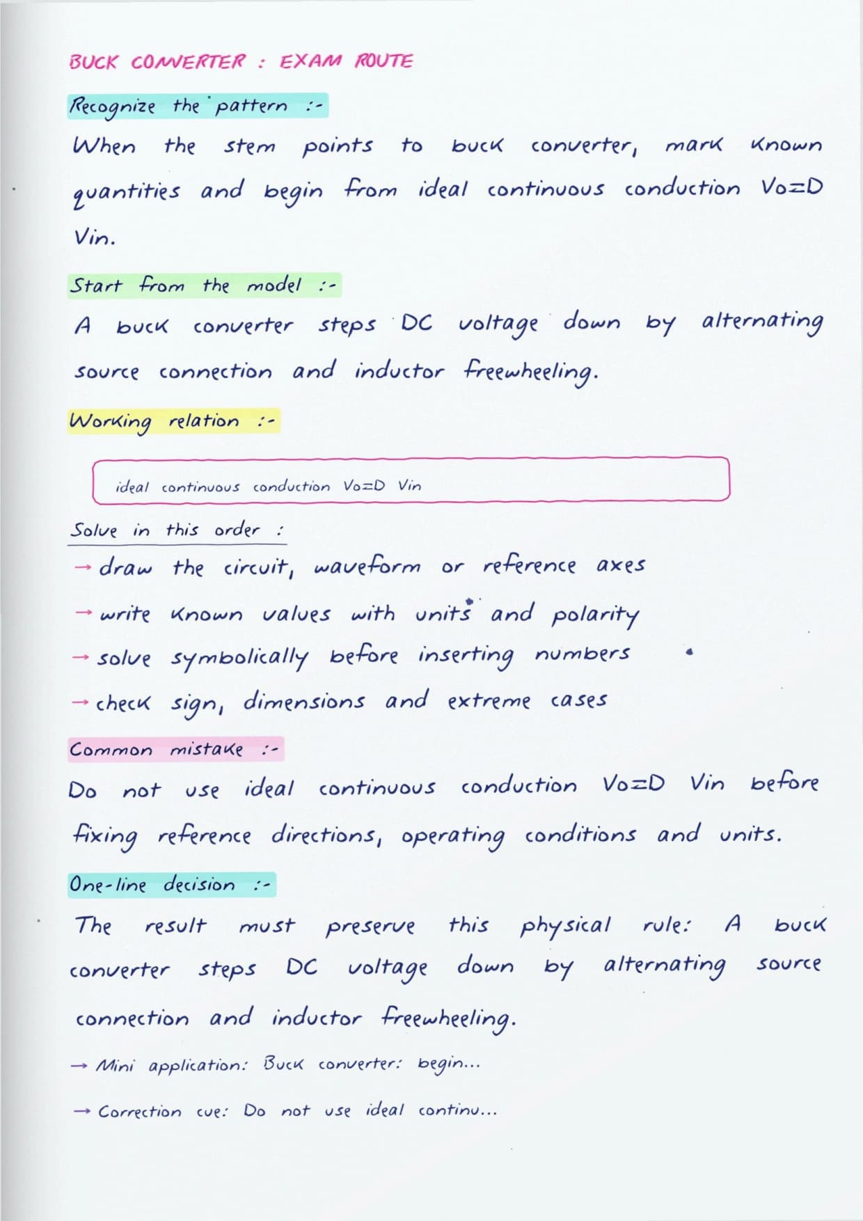
- Step-down chopper: average output, ripple, and duty ratio.
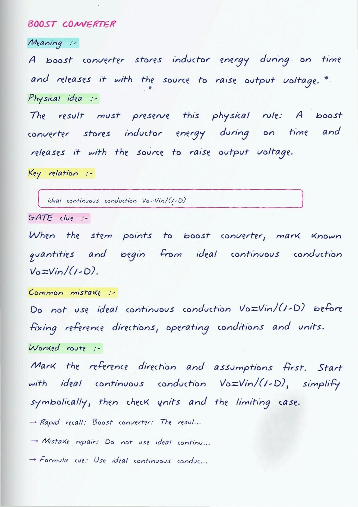
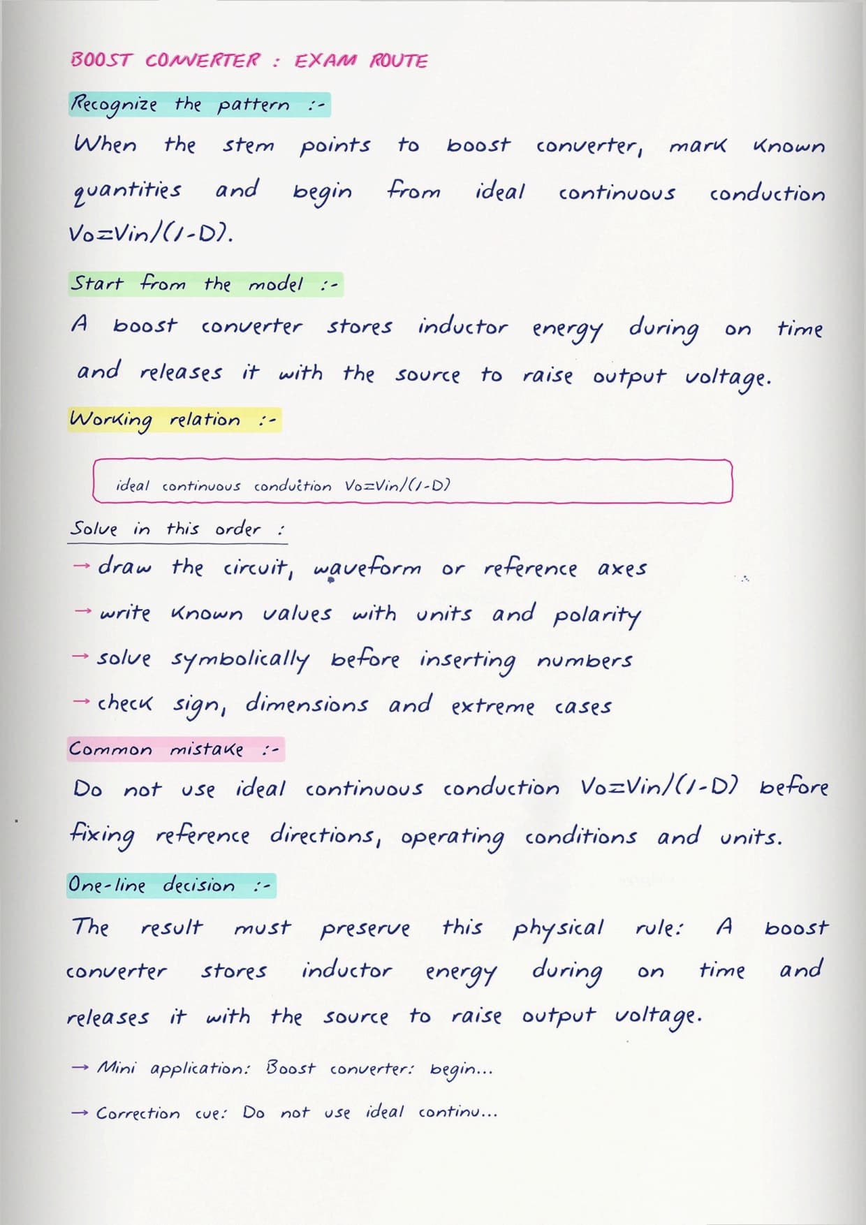
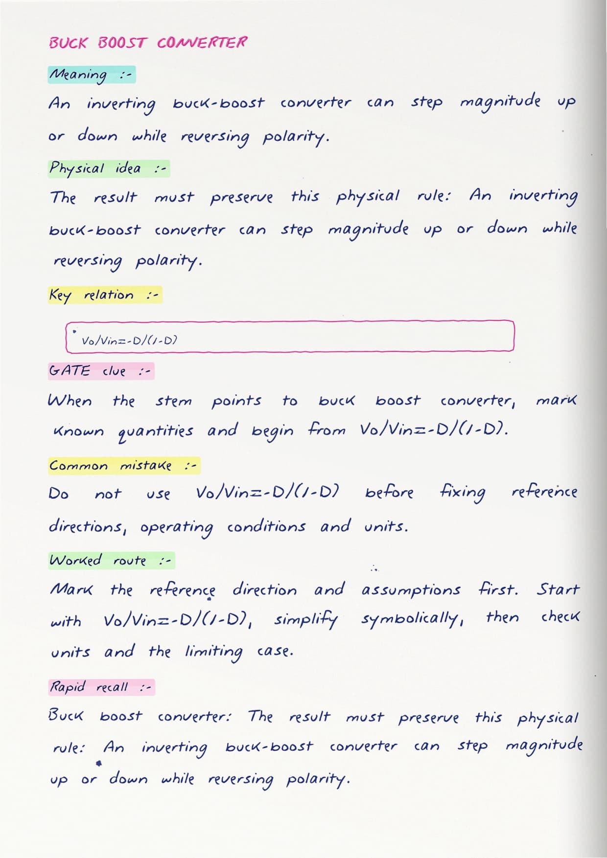
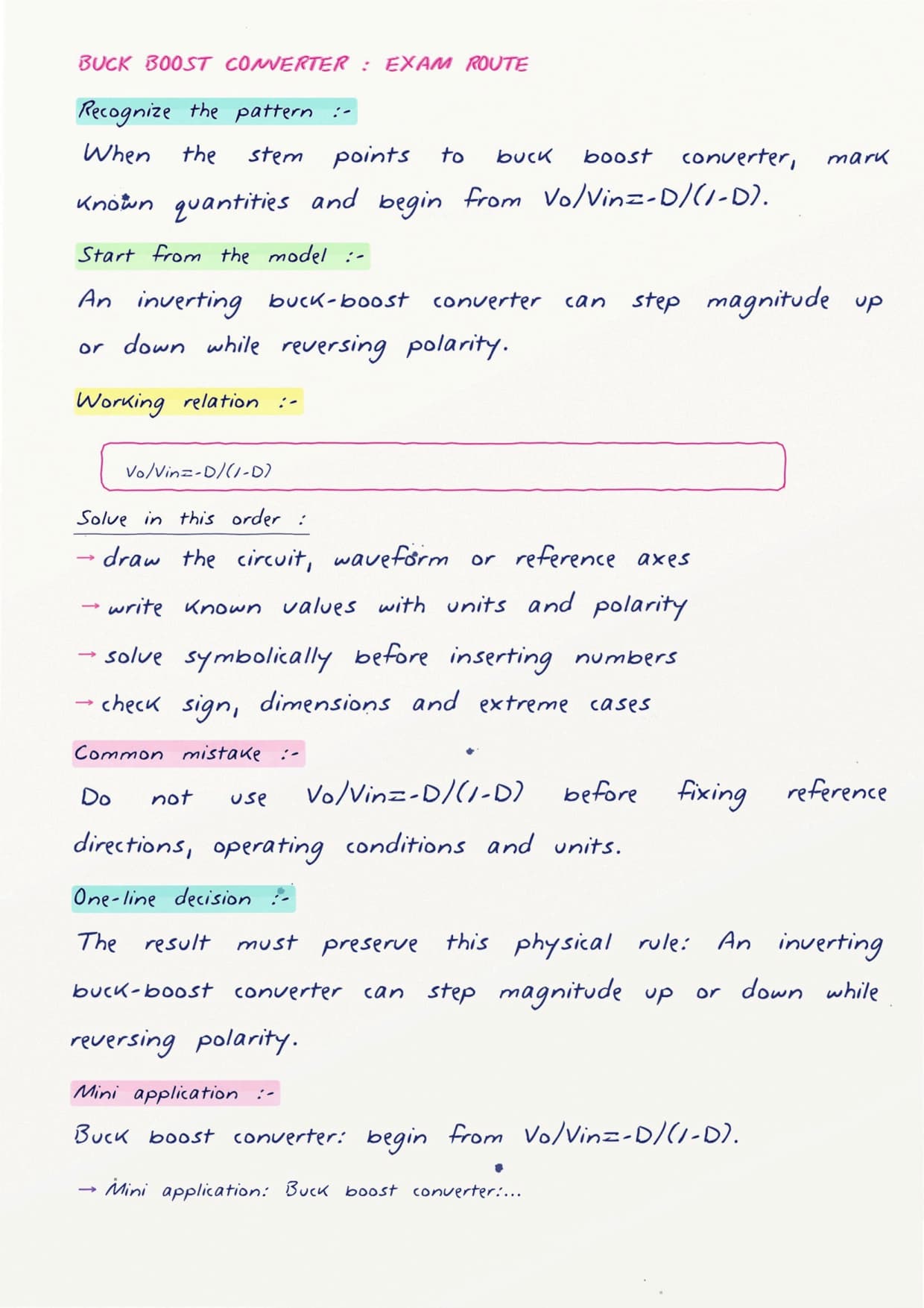
- Step-up and buck-boost converters and their voltage ratios.
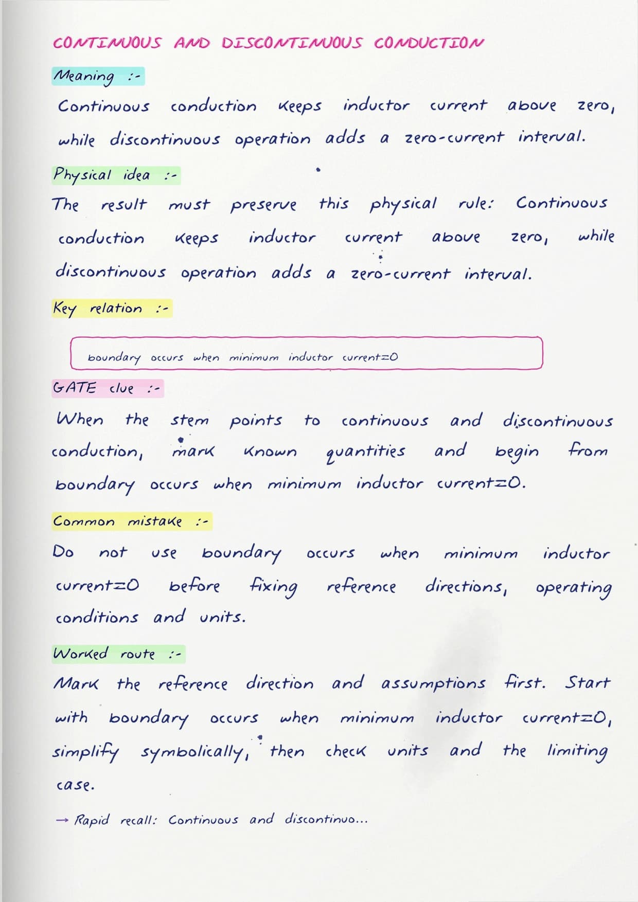
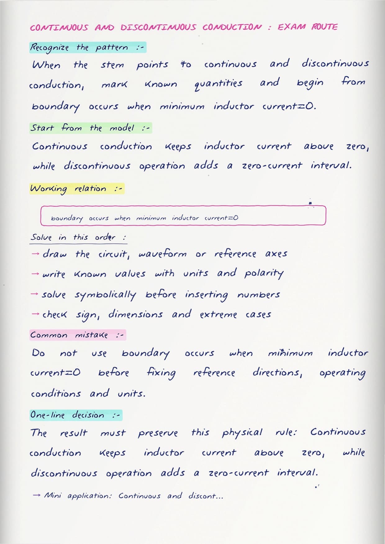
- Continuous and discontinuous conduction modes.
- Single-phase half-bridge and full-bridge inverters.
- Three-phase bridge inverter in 180-degree conduction.
- Square-wave output and its harmonic spectrum.
- Sinusoidal PWM and the role of the carrier frequency.
- Total harmonic distortion and output filtering.
How the Notes Are Organised
The sequence moves from DC-DC conversion to DC-AC conversion, which mirrors how the concepts build on each other. Choppers come first because the duty-ratio idea and switching waveform reappear in every later circuit. The inverter pages then reuse that switching picture to make AC.
Sinusoidal PWM sits last, once the square-wave inverter is understood, so the reason for shaping the pulses is already clear. A small spectrum sketch on that page shows how raising the carrier frequency pushes the harmonics higher up, where a filter removes them more easily. Every spread carries a boxed key result at the top for fast revision.
How GATE DC-DC Converters and Inverters Links to Other Topics
Power electronics threads through several parts of the paper, and the notes mark where these converters connect. Grasping them makes drive and rectifier questions easier.
- Rectifiers and AC-DC converters, sharing switching and averaging methods.
- Power semiconductor devices, where switch ratings set the limits.
- Electric drives, where choppers and inverters feed motors.
- Control systems, through closed-loop regulation of converter output.
Important Topics in GATE DC-DC Converters and Inverters
A handful of points carry most of the marks and hold the common traps. The notes highlight these with numbers so students do not lose easy questions.
- Boost converter voltage ratio, where the duty ratio sign is easy to flip.
- Discontinuous conduction, which changes the output relation entirely.
- Modulation index above one, where overmodulation distorts the output.
- Harmonic order in PWM output, set by the carrier-to-reference ratio.
- RMS and average confusion in chopper and inverter waveforms, which changes the final numerical answer.
How to Prepare GATE DC-DC Converters and Inverters with Handwritten Notes
This topic is best learned by drawing waveforms, not memorising results. Students should use these notes as a template and rebuild each waveform themselves.
- First read: trace each switching waveform and mark the on and off times.
- Second pass: derive the average and RMS values without help.
- PYQs: solve past chopper and inverter questions against the worked cases.
- Final week: revise the boxed results and the flagged traps only.
Why These Notes Help You Score Better
Converter questions turn on reading a waveform correctly, and these hand-drawn pages train exactly that skill. By tying each circuit to its switching picture and a worked value, they cut the confusion between average and RMS that costs marks. Since the same switching and averaging methods carry into rectifiers and drives, mastering these pages lifts a broad slice of the electronics group at once. The compact, boxed results also make a last-minute sweep fast and calm. Practised steadily, they help students turn power electronics into one of their strongest scoring areas.
GATE Electrical DC-DC Converters and Inverters Handwritten Notes FAQs
Ques. How much weight do converters and inverters carry in GATE Electrical?
Ans. Power electronics as a whole is a strong scoring area, and converters, inverters, and PWM together usually account for about 5 to 8 marks in the paper.
Ques. Do these notes explain sinusoidal PWM clearly?
Ans. Yes, a hand-drawn page shows how the sinusoidal reference crosses the triangular carrier to set each pulse width, and explains how the modulation index fixes the fundamental output.
Ques. Are buck, boost, and buck-boost converters all covered?
Ans. All three are covered with labelled waveforms and average-voltage working, along with their voltage ratios in continuous conduction mode.
Ques. What mistakes do students make most in this topic?
Ans. The usual slips are confusing average with RMS values, flipping the duty-ratio term in the boost relation, and forgetting how discontinuous conduction changes the output.



Comments