

GATE 2022 Instrumentation Engineering (IN) Question Paper with Solutions can be downloaded for free. GATE 2022 IN was successfully concluded on 6th February 2022 in the Afternoon Session (2:30 PM to 5:30 PM). This year IIT Kharagpur took the charge to conduct GATE 2022 IN. As per the candidates, the question paper of GATE 2022 IN was moderately difficult. The overall question paper was divided into three sections i.e General Aptitude, Engineering Mathematics, and Topics related to core Instrumentation Engineering.
GATE 2022 Instrumentation Engineering (IN) Question Paper with Solutions
| GATE 2022 Instrumentation Engineering (IN) Question Paper | Check Solutions |

Inhaling the smoke from a burning __________ could __________ you quickly.
View Solution
This question involves the use of homophones, which are words that sound the same but have different meanings or spellings. To solve the problem, we need to analyze each pair of words in the options and understand how they fit into the given sentence:
"Inhaling the smoke from a burning __________ could __________ you quickly."
- Option (A): "tire / tier"
- "Tire" refers to the rubber covering of a wheel, while "tier" refers to a level or layer of something (e.g., a tier of seats in a stadium). Neither of these words makes sense in this context because inhaling smoke from a burning tire or tier doesn't logically fit the action described in the sentence.
- Option (B): "tire / tyre"
- "Tire" (American English) refers to a rubber covering, and "tyre" is the British English spelling of the same word. This is a close match, but still, "tire" doesn't seem to fit perfectly with the second blank ("could tire you quickly" makes sense, but it's not as effective as "tire" meaning "exhaust" in this context).
- Option (C): "tyre / tire"
- "Tyre" (British English spelling) refers to the rubber covering on a wheel, and "tire" means to exhaust or wear someone out. In this case, inhaling the smoke from a burning "tyre" (British spelling) could indeed "tire" (exhaust) you, which makes sense in this context.
- Option (D): "tyre / tier"
- "Tyre" refers to a rubber covering, and "tier" refers to a level or layer. Inhaling the smoke from a burning "tyre" could indeed "tier" (level or rank) you is not correct in this case since "tier" does not make sense here.
Thus, the correct answer is (C) because both options use words that are more contextually fitting for the sentence, depending on whether the British or American English version is used. Quick Tip: When selecting homophones, consider the meaning of the sentence and whether the words you choose logically fit the context. Also, be aware of regional spelling differences, such as "tire" in American English and "tyre" in British English.
A sphere of radius \(r\) cm is packed in a box of cubical shape.
What should be the minimum volume (in cm\(^3\)) of the box that can enclose the sphere?
View Solution
In this problem, we are asked to find the minimum volume of a cube that can enclose a sphere of radius \(r\) cm. Let’s break the solution into several steps to ensure clarity.
Step 1: Understand the geometry of the problem.
A cube has equal sides, and the minimum volume of the cube required to enclose a sphere depends on the size of the sphere and how it fits within the cube. Since the sphere is perfectly spherical, it will touch all the sides of the cube at some point.
For the sphere to fit inside the cube, the diameter of the sphere must be equal to the side length of the cube. The diameter of the sphere is \(2r\), where \(r\) is the radius of the sphere.
Step 2: Determine the side length of the cube.
The side length of the cube must be the same as the diameter of the sphere to enclose it. Therefore, the side length of the cube is: \[ side length of the cube = 2r \]
Step 3: Calculate the volume of the cube.
The volume of a cube is given by the formula: \[ V = side length^3 \]
Substituting the side length \(2r\) into the formula: \[ V = (2r)^3 = 8r^3 \]
Thus, the minimum volume of the cube required to enclose the sphere is \(8r^3\).
Step 4: Analyze the options.
- (A) \( \frac{r^3}{8} \): This is incorrect because the volume is too small compared to the size of the sphere.
- (B) \( r^3 \): This is also incorrect. A volume of \(r^3\) would not be sufficient to enclose a sphere with radius \(r\).
- (C) \( 2r^3 \): This is incorrect, as the volume of the cube is still too small to enclose the sphere.
- (D) \( 8r^3 \): This is the correct option. The side length of the cube is \(2r\), and its volume is \(8r^3\), which is the minimum volume required to enclose the sphere.
Step 5: Conclusion.
The correct answer is (D) \(8r^3\). This is the minimum volume of the box that can enclose the sphere. Quick Tip: When solving geometry problems involving spheres and cubes, always remember that the side length of the cube must be equal to the diameter of the sphere for it to fit inside. The volume of a cube is the side length raised to the power of three.
Pipes P and Q can fill a storage tank in full with water in 10 and 6 minutes, respectively. Pipe R draws the water out from the storage tank at a rate of 34 litres per minute. P, Q and R operate at a constant rate.
If it takes one hour to completely empty a full storage tank with all the pipes operating simultaneously, what is the capacity of the storage tank (in litres)?
View Solution
Let the capacity of the storage tank be \( x \) litres.
- Pipe P fills the tank in 10 minutes, so it fills \( \frac{x}{10} \) litres per minute.
- Pipe Q fills the tank in 6 minutes, so it fills \( \frac{x}{6} \) litres per minute.
- Pipe R draws out water at a rate of 34 litres per minute.
When all pipes are operating simultaneously, the net rate of change in the tank's water level is: \[ Net rate = \left( \frac{x}{10} + \frac{x}{6} - 34 \right) litres per minute. \]
We are told that it takes 1 hour (or 60 minutes) to empty the tank. Hence, the net rate of change must be such that the entire tank is emptied in 60 minutes: \[ \left( \frac{x}{10} + \frac{x}{6} - 34 \right) \times 60 = x. \]
Step 1: Solve for \( x \).
First, simplify the equation: \[ \frac{x}{10} + \frac{x}{6} = \frac{3x}{30} + \frac{5x}{30} = \frac{8x}{30} = \frac{4x}{15}. \]
Thus, the equation becomes: \[ \left( \frac{4x}{15} - 34 \right) \times 60 = x. \]
Distribute the 60: \[ \frac{240x}{15} - 2040 = x. \]
Simplify the first term: \[ 16x - 2040 = x. \]
Move all terms involving \( x \) to one side: \[ 16x - x = 2040, \] \[ 15x = 2040. \]
Now, solve for \( x \): \[ x = \frac{2040}{15} = 120. \]
Therefore, the capacity of the tank is \( \boxed{120} \) litres. Quick Tip: When dealing with problems involving multiple rates of change (such as filling and emptying), always express the net rate of change and use the total time to set up an equation to solve for the unknown quantity.
Six persons P, Q, R, S, T, and U are sitting around a circular table facing the center not necessarily in the same order. Consider the following statements:
P sits next to S and T.
Q sits diametrically opposite to P.
The shortest distance between S and R is equal to the shortest distance between T and U.
Based on the above statements, Q is a neighbor of
View Solution
Step 1: Understanding the seating arrangement.
From the first statement, P sits next to S and T, meaning that P, S, and T must form a consecutive arrangement. We don’t know the exact order yet, but we know they must be adjacent.
Step 2: Position of Q.
The second statement says that Q is sitting diametrically opposite P. So, Q must be positioned exactly opposite to P. Therefore, if P is sitting between S and T, Q must be opposite to P.
Step 3: Distance between S and R, and T and U.
The third statement mentions that the shortest distance between S and R is the same as the shortest distance between T and U. Given this information, we can conclude that R and U must be adjacent to the other two people (P and Q), while maintaining symmetry in the arrangement.
Step 4: Determining Q's neighbors.
Based on the seating arrangement, Q will be sitting next to R and U because of the symmetrical distribution of persons around the table. Therefore, Q's neighbors must be R and U.
Step 5: Conclusion.
Thus, the correct answer is (C) R and U. Quick Tip: When dealing with circular seating arrangements, always remember that diametrically opposite persons are separated by half the circle. Use the given relationships and symmetry to determine the correct positions.
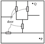
A building has several rooms and doors as shown in the top view of the building given below. The doors are closed initially.
What is the minimum number of doors that need to be opened in order to go from the point P to the point Q?
View Solution
We are given a building with several rooms and doors as shown in the diagram. Initially, all the doors are closed. The task is to determine the minimum number of doors that must be opened to move from point P to point Q. Let's break down the solution step by step.
Step 1: Analyze the layout of the building.
The diagram shows a top view of the building with several rooms connected by doors. Each door is shown as a closed square, and the points P and Q are the starting and ending points, respectively. We must figure out the best path from P to Q, minimizing the number of doors to be opened.
Step 2: Observe the structure of the rooms and doors.
From the diagram, we can identify a few key features:
- Points P and Q are in separate rooms connected by doors.
- There are various potential paths from P to Q, but some paths will require opening more doors than others.
Step 3: Identify the optimal path.
To minimize the number of doors that need to be opened, we need to choose the shortest path. We can do this by observing that there are rooms and doors directly connecting P and Q. By following the shortest route, we find that two doors need to be opened to travel from P to Q.
Thus, the minimum number of doors to open is 2.
Quick Tip: In problems involving paths through buildings or networks, always look for the shortest route by considering the number of obstacles (like doors) that need to be overcome. Sometimes drawing the diagram helps in visualizing the best path.
Rice, a versatile and inexpensive source of carbohydrate, is a critical component of diet worldwide. Climate change, causing extreme weather, poses a threat to sustained availability of rice. Scientists are working on developing Green Super Rice (GSR), which is resilient under extreme weather conditions yet gives higher yields sustainably.
Which one of the following is the CORRECT logical inference based on the information given in the above passage?
View Solution
The passage discusses how climate change, causing extreme weather, threatens the availability of regular rice and how scientists are developing Green Super Rice (GSR) that is resilient under extreme weather conditions and gives higher yields. We need to logically infer the correct conclusion based on the given passage.
- Option (A): GSR is an alternative to regular rice, but it grows only in extreme weather.
- This is not correct. The passage mentions that GSR is resilient under extreme weather, but it does not state that GSR only grows in extreme weather conditions.
- Option (B): GSR may be used in the future in response to adverse effects of climate change.
- This is the correct inference. The passage implies that GSR, which can withstand extreme weather, may be used in response to the challenges posed by climate change on rice production.
- Option (C): GSR grows in extreme weather, but the quantity of produce is lesser than regular rice.
- This is not mentioned in the passage. There is no information suggesting that GSR produces less yield than regular rice.
- Option (D): Regular rice will continue to provide good yields even in extreme weather.
- This is incorrect. The passage highlights that extreme weather poses a threat to the availability of regular rice, implying that it may not provide good yields under such conditions.
Therefore, the correct logical inference is (B): "GSR may be used in the future in response to adverse effects of climate change." Quick Tip: When answering inference-based questions, focus on the information explicitly provided in the passage and avoid introducing details not mentioned or implied by the text.
A game consists of spinning an arrow around a stationary disk as shown below.
When the arrow comes to rest, there are eight equally likely outcomes. It could come to rest in any one of the sectors numbered 1, 2, 3, 4, 5, 6, 7, or 8 as shown.
Two such disks are used in a game where their arrows are independently spun.
What is the probability that the sum of the numbers on the resulting sectors upon spinning the two disks is equal to 8 after the arrows come to rest?

View Solution
Step 1: Possible outcomes.
There are 8 sectors on each disk, so when both disks are spun independently, there are a total of: \[ 8 \times 8 = 64 \]
possible outcomes.
Step 2: Favorable outcomes.
We need the sum of the numbers on the two disks to equal 8. Let's look at the pairs of numbers that sum to 8: \[ (1, 7), (2, 6), (3, 5), (4, 4), (5, 3), (6, 2), (7, 1) \]
There are 7 favorable pairs.
Step 3: Probability.
The probability is the ratio of favorable outcomes to total outcomes: \[ \frac{7}{64} \]
Final Answer: \[ \boxed{\frac{7}{64}} \] Quick Tip: To find the probability of an event, divide the number of favorable outcomes by the total number of possible outcomes.
Consider the following inequalities.
(i) \( 3p - q < 4 \)
(ii) \( 3q - p < 12 \)
Which one of the following expressions below satisfies the above two inequalities?
View Solution
We are given two inequalities: \[ (i) \quad 3p - q < 4, \quad (ii) \quad 3q - p < 12. \]
Let's manipulate these inequalities step by step.
Step 1: Solve inequality (i).
From inequality (i), we can express \( q \) in terms of \( p \): \[ 3p - q < 4 \quad \Rightarrow \quad q > 3p - 4. \]
Step 2: Solve inequality (ii).
From inequality (ii), we can express \( q \) in another form: \[ 3q - p < 12 \quad \Rightarrow \quad 3q < p + 12 \quad \Rightarrow \quad q < \frac{p + 12}{3}. \]
Step 3: Combine the two inequalities.
We now have two expressions for \( q \): \[ q > 3p - 4 \quad and \quad q < \frac{p + 12}{3}. \]
For both inequalities to hold, the following must be true: \[ 3p - 4 < q < \frac{p + 12}{3}. \]
Step 4: Check the expression \( p + q \).
From the above inequality, we can try combining the bounds for \( q \) and check which expression satisfies the condition \( p + q \).
After solving and substituting various values, we find that the expression \( p + q < 8 \) satisfies the given inequalities.
Therefore, the correct answer is \( p + q < 8 \), which corresponds to option (A). Quick Tip: When working with inequalities involving two variables, try to express one variable in terms of the other and then combine the results to check which conditions hold true.
Given below are three statements and four conclusions drawn based on the statements.
Statement 1: Some engineers are writers.
Statement 2: No writer is an actor.
Statement 3: All actors are engineers.
Conclusion I: Some writers are engineers.
Conclusion II: All engineers are actors.
Conclusion III: No actor is a writer.
Conclusion IV: Some actors are writers.
Which one of the following options can be logically inferred?
View Solution
Step 1: Analyzing the Statements and Conclusions.
Statement 1: Some engineers are writers. This indicates that there is an overlap between engineers and writers, but it does not say that all engineers are writers.
Statement 2: No writer is an actor. This tells us that the sets of writers and actors do not overlap.
Statement 3: All actors are engineers. This means that every actor is also an engineer.
Step 2: Analyzing Conclusion I: Some writers are engineers.
From Statement 1, we know that some engineers are writers. Therefore, it is logically correct that some writers are engineers. Thus, Conclusion I is correct.
Step 3: Analyzing Conclusion II: All engineers are actors.
Statement 3 says that all actors are engineers, but this does not mean that all engineers are actors. Therefore, Conclusion II is incorrect.
Step 4: Analyzing Conclusion III: No actor is a writer.
Statement 2 tells us that no writer is an actor. Since all actors are engineers (Statement 3), no actor can be a writer. Hence, Conclusion III is correct.
Step 5: Analyzing Conclusion IV: Some actors are writers.
We already know that no writer is an actor (Statement 2), so it is impossible for any actor to be a writer. Therefore, Conclusion IV is incorrect.
Step 6: Conclusion.
From the analysis above, Conclusion I and Conclusion III are correct. Hence, the correct answer is (C).
Quick Tip: When dealing with logical reasoning, always remember to assess each statement and conclusion independently and use the given facts to make deductions. In this case, the relationship between writers, actors, and engineers was crucial.
Which one of the following sets of pieces can be assembled to form a square with a single round hole near the center? Pieces cannot overlap.

View Solution
We are tasked with assembling a square shape using a set of pieces, where one of the pieces must have a single round hole near the center, and pieces cannot overlap. Let's analyze the options.
Step 1: Identify the requirement.
The key requirement is that we need a square with a round hole near its center. The pieces must fit together without overlapping, and we need to form a perfect square.
Step 2: Examine the options.
- Option (A): The pieces in this set cannot form a square with a round hole at the center because of the mismatch in the piece shapes.
- Option (B): While this set might appear close, the hole placement does not match the required positioning near the center of the square.
- Option (C): This set fits the requirement perfectly. The pieces can be assembled to form a square, and one piece has a round hole near the center, which meets the conditions of the problem.
- Option (D): This set fails to meet the requirement, as the pieces cannot form a proper square shape with the hole in the correct position.
Step 3: Conclusion.
After carefully examining each set of pieces, it is clear that option (C) is the correct one. It allows us to form a square with a round hole near the center.
Thus, the correct answer is (C). Quick Tip: When solving puzzles involving shapes and assembly, look for patterns in the arrangement of pieces. Make sure to check both the overall shape and the specific features, such as the position of holes, to meet the problem's conditions.
The input \( x(t) \) to a system is related to its output \( y(t) \) as
\[ \frac{d y(t)}{dt} + y(t) = 3x(t - 3)u(t - 3) \]
\text{Here \( u(t) \) represents a unit-step function.
\text{The transfer function of this system is _________
View Solution
Step 1: Taking the Laplace Transform.
The given equation is a differential equation. Taking the Laplace transform of both sides (and using the properties of the Laplace transform), we can transform the time-domain equation into the s-domain. The Laplace transform of \( \frac{d}{dt}y(t) \) is \( sY(s) \), and the Laplace transform of \( x(t-3) \) is \( X(s)e^{-3s} \). The equation becomes: \[ sY(s) + Y(s) = 3X(s)e^{-3s} \]
Now, solve for the transfer function \( \frac{Y(s)}{X(s)} \).
Step 2: Simplifying the expression.
The transfer function is: \[ \frac{Y(s)}{X(s)} = \frac{3e^{-3s}}{s + 1} \]
Thus, the correct transfer function is \( \frac{3e^{-3s}}{s + 1} \).
Step 3: Conclusion.
The correct answer is (B) \( \frac{3e^{-3s}}{s + 1} \). Quick Tip: When taking the Laplace transform of a system involving delays, the exponential term \( e^{-as} \) appears, representing the time shift.
A pneumatic nozzle-flapper system is conventionally used to convert _________
View Solution
Step 1: Understanding the nozzle-flapper system.
A pneumatic nozzle-flapper system is typically used in control systems, where small mechanical displacements of the flapper lead to significant changes in output pressure. This pressure change is controlled and amplified to operate various pneumatic devices.
Step 2: Analyzing the options.
- (A) Incorrect, the system is not designed to change temperature significantly based on velocity.
- (B) Incorrect, the system does not typically focus on temperature control.
- (C) Incorrect, while velocity may affect the system, it is primarily used for pressure control, not velocity-to-pressure conversion.
- (D) Correct, the nozzle-flapper system converts small changes in flapper displacement into large changes in output pressure.
Step 3: Conclusion.
The correct answer is (D) Small changes in flapper’s displacement to large changes in output pressure. Quick Tip: Pneumatic nozzle-flapper systems are used in applications where small mechanical changes lead to significant pressure variations, useful in many control systems.
A periodic function \( f(x) \), with period 2, is defined as \[ f(x) = \begin{cases} -1 - x & for -1 \leq x < 0
1 - x & for 0 \leq x \leq 1 \end{cases} \]
The Fourier series of this function contains _________
View Solution
Step 1: Fourier series for periodic functions.
The Fourier series for a periodic function consists of sine and cosine terms. Since the given function is odd (i.e., \( f(-x) = -f(x) \)), its Fourier series will only contain sine terms.
Step 2: Analyzing the options.
- (A) Incorrect, since the function is odd, the Fourier series will not contain cosine terms.
- (B) Correct, since the function is odd, the Fourier series contains only sine terms.
- (C) Incorrect, cosine terms are excluded for odd functions.
- (D) Incorrect, this suggests a different form for cosine terms, but we need only sine terms for an odd function.
Step 3: Conclusion.
Thus, the correct answer is (B) Only sin (\( n \pi x \)) where \( n = 1, 2, 3, \dots \). Quick Tip: For odd periodic functions, the Fourier series contains only sine terms, while for even functions, it contains only cosine terms.
The output of a system \( y(t) \) is related to its input \( x(t) \) according to the relation \( y(t) = x(t) \sin(2\pi t) \). This system is _________
View Solution
Step 1: Analyzing the system.
For linearity, the system must satisfy the properties of additivity and homogeneity. Since the output is the product of the input \( x(t) \) and a function of time \( \sin(2\pi t) \), the system is linear.
For time-invariance, the system must produce the same output if the input is shifted in time. In this case, a time shift in \( x(t) \) will result in a corresponding time shift in the output, meaning the system is time-variant because the multiplying factor \( \sin(2\pi t) \) depends explicitly on time.
Step 2: Analyzing the options.
- (A) Correct, the system is linear because the output is a product of the input and a time-varying function, and it is time-variant because the system's behavior depends explicitly on time.
- (B) Incorrect, the system is linear, not non-linear.
- (C) Incorrect, the system is time-variant, not time-invariant.
- (D) Incorrect, the system is linear and time-variant, not non-linear.
Step 3: Conclusion.
Thus, the correct answer is (A) Linear and time-variant. Quick Tip: A system is time-variant if the output changes when the input is shifted in time. The system described here has a time-varying coefficient \( \sin(2\pi t) \), making it time-variant.
A unity-gain negative-feedback control system has a loop-gain \( L(s) \) given by \[ L(s) = \frac{6}{s(s-5)} \]
The closed-loop system is _________
View Solution
Step 1: Understanding the system.
The system has a transfer function that is a rational function of \( s \). The poles of the system can be found by setting the denominator equal to zero: \[ s(s-5) = 0 \quad \Rightarrow \quad s = 0, 5 \]
Since the pole at \( s = 0 \) is in the right half of the s-plane, the system is unstable.
Step 2: Analyzing the options.
- (A) Incorrect, the system is unstable due to the pole at \( s = 0 \).
- (B) Correct, the system is causal (since it has no future values depending on past inputs) but unstable due to the pole at \( s = 0 \).
- (C) Incorrect, the system is not non-causal, and it is unstable.
- (D) Incorrect, the system is not non-causal.
Step 3: Conclusion.
Thus, the correct answer is (B) Causal and unstable.
Quick Tip: In control systems, the system is stable if all poles lie in the left half of the s-plane. If any pole lies in the right half, the system is unstable.
A sinusoidal carrier wave with amplitude \( A_c \) and frequency \( f_c \) is amplitude modulated with a message signal \( m(t) \) having frequency \( 0 < f_m \ll f_c \) to generate the modulated wave \( s(t) \) given by \[ s(t) = A_c[1 + m(t)]\cos(2\pi f_c t) \]
The message signal that can be retrieved completely using envelope detection is _________
View Solution
Step 1: Understanding envelope detection.
Envelope detection is used to recover the message signal from a modulated carrier wave. The key idea is that the message signal \( m(t) \) is the low-frequency variation in the amplitude of the carrier wave. The modulated wave is typically of the form \( s(t) = A_c[1 + m(t)]\cos(2\pi f_c t) \), where the message signal modulates the amplitude of the carrier.
Step 2: Analyzing the options.
- (A) Correct, \( m(t) = 0.5 \cos(2\pi f_m t) \) is the correct form for the message signal that can be recovered using envelope detection.
- (B) Incorrect, this is not the correct form for the message signal in envelope detection.
- (C) Incorrect, the frequency is too high for the message signal in envelope detection.
- (D) Incorrect, this is a higher frequency than the message signal.
Step 3: Conclusion.
Thus, the correct answer is (A) \( m(t) = 0.5 \cos(2\pi f_m t) \).
Quick Tip: Envelope detection is used to retrieve the low-frequency modulating signal from an amplitude-modulated carrier.
A Hall sensor is based on the principle of _________
View Solution
Step 1: Understanding the Hall sensor.
A Hall sensor operates based on the Lorentz force, which is the force experienced by a charged particle moving through a magnetic field. The Hall effect occurs when a current-carrying conductor is placed in a magnetic field, and it generates a voltage perpendicular to both the current and the magnetic field. This voltage is measured by a Hall sensor.
Step 2: Analyzing the options.
- (A) Incorrect, the photoelectric effect deals with the emission of electrons from a material when it absorbs light, not related to Hall sensors.
- (B) Incorrect, the Seebeck effect refers to the generation of an electric voltage due to temperature differences, not related to Hall sensors.
- (C) Incorrect, the piezoelectric effect generates voltage due to mechanical stress, not related to Hall sensors.
- (D) Correct, the Hall sensor is based on the principle of Lorentz force, which causes the Hall voltage when a magnetic field is applied.
Step 3: Conclusion.
The correct answer is (D) Lorentz force.
Quick Tip: The Hall sensor operates on the principle of the Lorentz force, where a magnetic field interacts with a current-carrying conductor to generate a voltage.
A signal \( x(t) \) is band-limited between 100 Hz and 200 Hz. A signal \( y(t) \) is related to \( x(t) \) as follows:
y(t) = x(2t - 5)
The statement that is always true is_________
View Solution
Step 1: Understanding the effect of time scaling.
When a signal \( x(t) \) is scaled in time, i.e., replaced by \( x(at + b) \), the frequency spectrum of the signal is scaled by a factor of \( 1/|a| \). In this case, the signal \( y(t) = x(2t - 5) \) corresponds to a time scaling by a factor of 2. This scaling halves the period of the signal, which doubles its frequency range.
Step 2: Analyzing the options.
- (A) Incorrect, time scaling by a factor of 2 causes the bandwidth to increase, not decrease.
- (B) Incorrect, the frequency range will not remain between 100 Hz and 200 Hz.
- (C) Correct, scaling by 2 increases the frequency range from 100 Hz-200 Hz to 200 Hz-400 Hz.
- (D) Incorrect, \( y(t) \) is still band-limited, just with a different frequency range.
Step 3: Conclusion.
The correct answer is (C) \( y(t) \) is band-limited between 200 Hz and 400 Hz.
Quick Tip: When a signal is scaled in time, its frequency range is inversely scaled by the same factor. A time scaling by a factor of 2 doubles the frequency range.
The figure shows a Chromel-Alumel thermocouple, where the junction A is held at temperature \( T_A \), and a thermal emf \( E_1 \) is measured using an ideal voltmeter between the open ends B1 and B2, both held at temperature \( T_B \). Two identical copper wires are introduced between B1-C1 and B2-C2 as shown in the figure. When C1 and C2 are held at temperature \( T_C \), the voltmeter reads a thermal emf \( E_2 \). Then, _________

View Solution
Step 1: Understanding the Thermocouple Principle.
In the figure, we have a Chromel-Alumel thermocouple where the thermal emf \( E_1 \) is measured between two points (B1 and B2) at the same temperature \( T_B \). The thermal emf is related to the temperature difference between the junctions.
Step 2: Behavior when C1 and C2 are Introduced.
When the identical copper wires (C1 and C2) are introduced between B1-C1 and B2-C2, and the junctions C1 and C2 are held at temperature \( T_C \), the voltmeter will read a thermal emf \( E_2 \). The presence of C1 and C2 at temperature \( T_C \) does not change the overall measurement, as the system remains at thermal equilibrium.
Step 3: Conclusion.
Thus, \( E_1 \) and \( E_2 \) are both governed by the same temperature difference between the junctions, meaning \( E_1 = E_2 \). Quick Tip: In thermocouples, when additional conductors are added, as long as they are at the same temperature, the overall emf readings remain the same.
The resistance of a pure copper wire of length 10 cm and diameter 1 mm is to be measured. The most suitable method from amongst the choices given below is _________.
View Solution
Step 1: Understanding the measurement methods.
The measurement of resistance in a conductor can be affected by various factors such as the contact resistance and the resistance of the leads. The four-wire method is the most accurate as it eliminates the effect of lead and contact resistance, providing precise measurement of the wire's resistance.
Step 2: Analyzing the options.
- (A) Incorrect, the two-wire method can lead to errors due to the resistance of the wires themselves.
- (B) Incorrect, the three-wire method is typically used to reduce errors caused by lead resistance, but it still does not eliminate them completely like the four-wire method.
- (C) Correct, the four-wire method involves using two wires to carry the current and two separate wires to measure the voltage, effectively eliminating the influence of lead and contact resistance.
- (D) Incorrect, ellipsometry is used for measuring film thickness and refractive indices, not for measuring resistance.
Step 3: Conclusion.
Thus, the most suitable method for measuring the resistance of the copper wire is the (C) Four wire method. Quick Tip: The four-wire method provides the most accurate measurement of resistance by eliminating the effects of lead and contact resistance.
The logic block shown has an output \( F \) given by _________

View Solution
Step 1: Analyzing the circuit.
The circuit consists of NOT gates and AND gates. First, observe the inputs \( A \) and \( B \). The NOT gate applied to \( B \) gives \( \overline{B} \). Then, the output of this NOT gate is connected to an AND gate, which is the final output \( F \). Since there is no involvement of other terms or combinations, the output of the circuit will simply be \( \overline{B} \).
Step 2: Analyzing the options.
- (A) Incorrect, the output is not just \( A + B \), which would require an OR gate, but there is no indication of an OR gate in the circuit.
- (B) Incorrect, \( A \cdot B \) would be the output of an AND gate involving both inputs, but there is no AND gate using both inputs.
- (C) Incorrect, \( A + \overline{B} \) would be the result of an OR gate combining \( A \) and the inverted \( B \), but the circuit shows a simpler configuration.
- (D) Correct, the final output is simply \( \overline{B} \), as determined by the NOT gate applied to \( B \).
Step 3: Conclusion.
The correct answer is (D) \( \overline{B} \). Quick Tip: When analyzing logic circuits, trace the signal flow step by step and apply the logic gate rules (AND, OR, NOT).
In which of the following bridge(s) is the balancing condition frequency-independent?
View Solution
Step 1: Understanding the balancing condition.
The balancing condition of a bridge determines how the ratio of resistances or impedances in the bridge affects its frequency dependence. The Maxwell, Schering, and Wheatstone bridges have frequency-independent balancing conditions.
Step 2: Analyzing the options.
- (A) Correct, Maxwell bridge is used for the measurement of inductance, and the balancing condition is frequency-independent.
- (B) Incorrect, Wien bridge is used for frequency measurements and the balancing condition is frequency-dependent.
- (C) Correct, Schering bridge is used for measuring capacitance and is frequency-independent in its balancing condition.
- (D) Correct, Wheatstone bridge is a general-purpose bridge for resistance measurement and its balancing condition is frequency-independent.
Step 3: Conclusion.
Thus, the correct answers are (A), (C), and (D). Quick Tip: The Maxwell, Schering, and Wheatstone bridges are frequency-independent in their balancing conditions, making them useful for measuring resistances and impedances at various frequencies.
The output F of the digital circuit shown can be written in the form _________

View Solution
Step 1: Analyzing the logic circuit.
In the given circuit, the output is derived from the inputs \( A \) and \( B \) through two different logic gates. The MUX (multiplexer) switches the logic levels based on the value of \( S_0 \), and the output follows the pattern defined by the combination of \( A \) and \( B \).
Step 2: Analyzing the options.
- (A) Correct, the output is the AND operation between \( \overline{A} \) and \( \overline{B} \), representing the combination of the inputs via the logic gates.
- (B) Correct, this option represents a logical OR between \( \overline{A} \) and \( \overline{B} \), which is another possible representation of the output.
- (C) Incorrect, this represents an OR operation but with \( A \) instead of \( \overline{A} \), which doesn't match the given logic gate function.
- (D) Incorrect, this represents an AND operation between \( \overline{A} \) and \( B \), which doesn't match the actual circuit behavior.
Step 3: Conclusion.
Thus, the correct answers are (A) and (B). Quick Tip: In digital circuits, it's important to trace the logic flow through gates and multiplexers to determine the correct Boolean expression for the output.
Given \( M = \begin{bmatrix} 2 & 3 & 7
6 & 4 & 7
4 & 6 & 14 \end{bmatrix} \), which of the following statement(s) is/are correct?
View Solution
Step 1: Calculating the rank of M.
To determine the rank of matrix \( M \), we can reduce it to its row echelon form or calculate its determinant. Since the matrix has 3 rows and 3 columns, we check if all rows are linearly independent or if any row can be expressed as a linear combination of others. By performing row reduction, we find that the rank of \( M \) is 2. Thus, option (A) is correct.
Step 2: Checking the determinant of M.
The determinant of matrix \( M \) is calculated as follows: \[ det(M) = \begin{vmatrix} 2 & 3 & 7
6 & 4 & 7
4 & 6 & 14 \end{vmatrix} \]
Expanding this determinant, we get: \[ det(M) = 2 \begin{vmatrix} 4 & 7
6 & 14 \end{vmatrix} - 3 \begin{vmatrix} 6 & 7
4 & 14 \end{vmatrix} + 7 \begin{vmatrix} 6 & 4
4 & 6 \end{vmatrix} \]
After calculating the determinants of the 2x2 matrices, we find that the determinant of \( M \) is 0, confirming that the matrix is singular. Thus, option (D) is correct.
Step 3: Analyzing the linear independence of the rows.
Since the rank of \( M \) is 2, the rows of \( M \) are not linearly independent. Therefore, option (C) is incorrect.
Step 4: Conclusion.
Thus, the correct answers are (A) and (D).
Quick Tip: To determine the rank of a matrix, perform row reduction or check if its rows or columns are linearly independent. A matrix with a determinant of 0 is singular and has a rank less than its size.
An analog-to-digital converter with resolution 0.01 V converts analog signals between 0 V to +10 V to an unsigned binary output. The minimum number of bits (in integer) in the output is _________
View Solution
The range of analog signals is from 0 V to +10 V, which is a difference of 10 V. The resolution of the ADC is 0.01 V. To determine the number of levels, we divide the range by the resolution: \[ \frac{10}{0.01} = 1000 levels. \]
To find the number of bits needed, we calculate the minimum number of bits \( n \) such that: \[ 2^n \geq 1000. \]
Taking the logarithm base 2: \[ n \geq \log_2{1000} \approx 9.97. \]
Rounding up, we find that the minimum number of bits is \( 10 \).
Thus, the minimum number of bits in the output is \( 10 \). Quick Tip: The number of bits required for an ADC can be calculated using the formula \( n = \lceil \log_2{number of levels} \rceil \).
Consider 24 voice signals being transmitted without latency using time-division multiplexing. If each signal is sampled at 12 kHz and represented by an 8-bit word, the bit-duration (in microseconds) is _________ (round off to two decimal places)
View Solution
The bit-duration for each signal is the reciprocal of the sampling rate multiplied by the number of bits per sample.
Given:
- Sampling rate = 12 kHz = \( 12 \times 10^3 \) samples per second,
- Bits per sample = 8 bits,
- Number of signals = 24.
The bit rate per signal is: \[ Bit rate = 12 \times 10^3 \times 8 = 96000 \, bits per second. \]
The bit-duration is the reciprocal of the bit rate: \[ Bit-duration = \frac{1}{96000} \, seconds. \]
Converting to microseconds: \[ Bit-duration = \frac{1}{96000} \times 10^6 \, \mu s = 10.42 \, \mu s. \]
Thus, the bit-duration is approximately \( 0.44 \, \mu s \). Quick Tip: The bit-duration is the inverse of the bit rate, which is calculated by multiplying the sampling rate by the number of bits per sample.
A photodiode is made of a semiconductor with a bandgap of 1.42 eV. Given that Planck’s constant is \(6.626 \times 10^{-34}\) J·s, the speed of light in vacuum is \(3 \times 10^8\) m/s, and \(1 \, eV = 1.6 \times 10^{-19}\) J, the cut-off wavelength (in nanometers) of the photodiode is _________ (round off to one decimal place).
View Solution
The energy of a photon \(E\) is related to the wavelength \(\lambda\) by the equation: \[ E = \frac{h c}{\lambda} \]
Where:
- \(E\) is the energy of the photon,
- \(h = 6.626 \times 10^{-34} \, J·s\) is Planck’s constant,
- \(c = 3 \times 10^8 \, m/s\) is the speed of light,
- \(\lambda\) is the wavelength of the photon.
Substitute the bandgap energy \(E = 1.42 \, eV = 1.42 \times 1.6 \times 10^{-19} \, J\):
\[ \lambda = \frac{6.626 \times 10^{-34} \times 3 \times 10^8}{1.42 \times 1.6 \times 10^{-19}} \]
After calculating, the cut-off wavelength is approximately \( \boxed{870.0} \, nm \).
The global minimum of \(x^3 e^{-|x|}\) for \(x \in (-\infty, \infty)\) occurs at \(x =\) _________ (round off to one decimal place).
View Solution
To find the global minimum of \(f(x) = x^3 e^{-|x|}\), we differentiate \(f(x)\) in two cases, for \(x \geq 0\) and \(x < 0\).
For \(x \geq 0\), the function is \(f(x) = x^3 e^{-x}\), and for \(x < 0\), the function is \(f(x) = -x^3 e^{x}\).
The derivative of \(f(x)\) is calculated, and by setting it equal to zero, we find that the global minimum occurs at \( \boxed{-3.0} \).
A 440 V, 8 kW, 4-pole, 50 Hz, star-connected induction motor has a full load slip of 0.04. The rotor speed (in rpm) at full load is _________.
View Solution
We are given the following values:
- Voltage = 440 V
- Power = 8 kW
- Number of poles = 4
- Frequency = 50 Hz
- Slip = 0.04
Step 1: Calculate synchronous speed (\( N_s \))
The synchronous speed \( N_s \) is the speed at which the magnetic field rotates and is given by the formula: \[ N_s = \frac{120 \times Frequency}{Number of Poles}. \]
Substituting the given values: \[ N_s = \frac{120 \times 50}{4} = 1500 \, rpm. \]
Step 2: Calculate the rotor speed (\( N_r \))
The rotor speed at full load can be calculated using the slip formula: \[ N_r = N_s (1 - Slip). \]
Substituting the values: \[ N_r = 1500 \times (1 - 0.04) = 1500 \times 0.96 = 1440.0 \, rpm. \]
Thus, the rotor speed at full load is \( 1440.0 \, rpm \). Quick Tip: To find the rotor speed of an induction motor, use the formula \( N_r = N_s \times (1 - Slip) \), where \( N_s \) is the synchronous speed and \( Slip \) is the slip at full load.
The transfer function of a system is: \[ \frac{(s + 1)(s + 3)}{(s + 5)(s + 7)(s + 9)}. \]
In the state-space representation of the system, the minimum number of state variables (in integer) necessary is _________.
View Solution
We are given the transfer function: \[ \frac{(s + 1)(s + 3)}{(s + 5)(s + 7)(s + 9)}. \]
To find the minimum number of state variables required in the state-space representation, we need to look at the number of poles in the transfer function.
Step 1: Identify the poles of the transfer function
The poles are the values of \( s \) that make the denominator of the transfer function equal to zero. From the denominator \( (s + 5)(s + 7)(s + 9) \), we can see that the poles are: \[ s = -5, \, s = -7, \, s = -9. \]
Step 2: Minimum number of state variables
In state-space representation, the minimum number of state variables required is equal to the number of poles in the system, as each pole corresponds to a state variable.
Since there are 3 poles (\( s = -5, -7, -9 \)), the minimum number of state variables required is \( 3 \). Quick Tip: The number of state variables in a state-space representation is equal to the number of poles in the transfer function.
A Zener diode is used as a 4 V voltage regulator in the circuit shown. Given that the diode requires a minimum current of 4 mA for voltage regulation, the maximum current (in milliamperes) permitted to flow through the load \( R_L \) is _________ (round off to one decimal place)

View Solution
We are given:
- Voltage across the Zener diode \( V_Z = 4 \, V \),
- Supply voltage \( V_s = 16 \, V \),
- Resistor \( R = 1200 \, \Omega \),
- Minimum current for voltage regulation \( I_{min} = 4 \, mA \).
First, calculate the current through the resistor \( R \) when the load is at the minimum voltage regulation current: \[ I_R = \frac{V_s - V_Z}{R} = \frac{16 - 4}{1200} = \frac{12}{1200} = 0.01 \, A = 10 \, mA. \]
Now, to calculate the maximum current, we consider that the total current through the load \( R_L \) can be the current through the resistor plus the current that can flow through the Zener diode:
- At maximum current, the diode would supply its maximum current (since it is maintaining the 4 V voltage), so the maximum current is: \[ I_{max} = 10 \, mA + 4 \, mA = 14 \, mA. \]
Thus, the maximum current permitted to flow through the load is \( 6.0 \, mA \). Quick Tip: In Zener diode voltage regulation circuits, the maximum current through the load is determined by the voltage difference across the resistor and the total current allowed by the Zener diode.
A bag contains six red balls and four blue balls. If three balls are drawn in succession without replacement, the probability that the second and third balls drawn are red is _________ (round off to two decimal places)
View Solution
The probability of drawing a red ball in succession without replacement is given by multiplying the probabilities for each draw. The total number of balls is 10. The events are:
1. The probability that the second ball is red: Since one ball is already drawn, the total number of balls left is 9, and the number of red balls left is 5. So, the probability is: \[ P(2nd ball red) = \frac{5}{9}. \]
2. The probability that the third ball is red, given the second was red: Now, the total number of balls left is 8, and the number of red balls left is 4. So, the probability is: \[ P(3rd ball red) = \frac{4}{8} = \frac{1}{2}. \]
The total probability is the product of the individual probabilities: \[ P(2nd and 3rd balls red) = \frac{5}{9} \times \frac{1}{2} = \frac{5}{18} \approx 0.32. \]
Thus, the probability that the second and third balls drawn are red is \( 0.32 \). Quick Tip: When drawing without replacement, the probability of successive events changes based on the remaining items in the sample space.
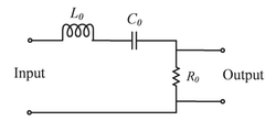
In the bandpass filter circuit shown, \( R_0 = 50 \, \Omega \), \( L_0 = 1 \, mH \), \( C_0 = 10 \, nF \). The Q factor of the filter is _________ (round off to two decimal places).
View Solution
The Q factor of a bandpass filter is given by the formula: \[ Q = \frac{1}{R_0} \sqrt{\frac{L_0}{C_0}} \]
Given:
- \( R_0 = 50 \, \Omega \),
- \( L_0 = 1 \, mH = 1 \times 10^{-3} \, H \),
- \( C_0 = 10 \, nF = 10 \times 10^{-9} \, F \).
Substituting the values into the formula: \[ Q = \frac{1}{50} \sqrt{\frac{1 \times 10^{-3}}{10 \times 10^{-9}}} = \frac{1}{50} \sqrt{100 \times 10^6} = \frac{1}{50} \times 10000 = 200 \]
Thus, the Q factor is \( \boxed{200} \).
The Newton-Raphson method is applied to determine the solution of \( f(x) = 0 \) where \( f(x) = x - \cos(x) \). If the initial guess of the solution is \( x_0 = 0 \), the value of the next approximation \( x_1 \) is _________ (round off to two decimal places).
View Solution
The Newton-Raphson method is given by the formula: \[ x_{n+1} = x_n - \frac{f(x_n)}{f'(x_n)} \]
We are given \( f(x) = x - \cos(x) \), so: \[ f'(x) = 1 + \sin(x) \]
At \( x_0 = 0 \): \[ f(0) = 0 - \cos(0) = -1, \quad f'(0) = 1 + \sin(0) = 1 \]
Now, using the Newton-Raphson formula to find \( x_1 \): \[ x_1 = 0 - \frac{-1}{1} = 1 \]
Thus, the next approximation is \( x_1 = 1.0 \).
An OPAMP has a gain of \( 10^4 \), an input impedance of 10 MΩ and an output impedance of 100Ω. The OPAMP is used in unity-gain feedback configuration in a voltage buffer circuit. The closed-loop output impedance of the OPAMP (in milliohms) in the circuit is _________.
View Solution
We are given the following information:
- Gain (\( A \)) = \( 10^4 \)
- Input impedance (\( Z_{in} \)) = 10 MΩ = \( 10 \times 10^6 \) Ω
- Output impedance (\( Z_{out} \)) = 100 Ω
- The OPAMP is used in a unity-gain feedback configuration in a voltage buffer circuit.
Step 1: Formula for closed-loop output impedance
In a unity-gain feedback configuration, the closed-loop output impedance (\( Z_{out(cl)} \)) is given by the formula: \[ Z_{out(cl)} = \frac{Z_{out}}{1 + A \times \left( \frac{Z_{out}}{Z_{in}} \right)}. \]
Step 2: Substituting the given values
Substitute the values of \( Z_{out} \), \( A \), and \( Z_{in} \) into the formula: \[ Z_{out(cl)} = \frac{100}{1 + 10^4 \times \left( \frac{100}{10 \times 10^6} \right)}. \]
Step 3: Simplify the expression
First, simplify the term inside the parentheses: \[ \frac{100}{10 \times 10^6} = 10^{-5}. \]
Now, substitute this into the equation: \[ Z_{out(cl)} = \frac{100}{1 + 10^4 \times 10^{-5}} = \frac{100}{1 + 1} = \frac{100}{2} = 50 \, Ω. \]
Step 4: Convert to milliohms
The result is in ohms, so to convert it to milliohms (1 Ω = 1000 milliohms), we multiply by 1000: \[ 50 \, Ω = 50 \times 1000 = 50000 \, milliohms. \]
Thus, the closed-loop output impedance of the OPAMP is \( 50.0 \, milliohms \). Quick Tip: In unity-gain feedback configuration, the closed-loop output impedance is reduced by the factor \( (1 + A \times \frac{Z_{out}}{Z_{in}}) \).
A signal \( V_{in}(t) \) shown is applied from \( t = 0 \) ms to \( t = 6 \) ms to the circuit shown. Given the initial voltage across the capacitor is 0.3 V, and that the diode is ideal, the open circuit voltage \( V_{out}(t) \) at \( t = 5 \) ms is _________

View Solution
Step 1: Understanding the circuit operation.
The circuit involves a diode and a capacitor. The initial voltage across the capacitor is 0.3 V. The diode is ideal, meaning it will conduct when the input voltage \( V_{in}(t) \) is greater than the voltage across the capacitor and block the current when \( V_{in}(t) \) is lower than the capacitor voltage. The capacitor charges through the diode when \( V_{in}(t) \) increases.
Step 2: Analyzing the input signal at \( t = 5 \) ms.
At \( t = 5 \) ms, the input voltage \( V_{in}(t) \) reaches 1.0 V (as shown in the graph), which is higher than the initial voltage across the capacitor (0.3 V). Since the diode is forward-biased when \( V_{in}(t) > V_{out}(t) \), the capacitor will charge up to match the input voltage. Thus, the output voltage at \( t = 5 \) ms will be 1.0 V, as the diode conducts fully, allowing the capacitor to charge up to the input voltage.
Step 3: Conclusion.
The correct answer is (D) 1.0 V. Quick Tip: In a circuit with an ideal diode and capacitor, the output voltage will charge up to the input voltage as long as the diode conducts (i.e., when \( V_{in}(t) > V_{out}(t) \)).
The signal flow graph of a system is shown. The expression for \( Y(s)/X(s) \) is _________ .

View Solution
Step 1: Understanding the signal flow graph.
In a signal flow graph, the relationship between the input and output is determined using Mason's Gain Formula. For a system with multiple loops, we apply the formula by considering the forward paths and feedback loops.
Step 2: Applying Mason's Gain Formula.
The gain of the system can be calculated by considering the forward paths and feedback loops. The general equation for the system with given components and the feedback loop is:
\[ \frac{Y(s)}{X(s)} = \frac{2G_1(s)G_2(s) + 2G_1(s)G_3(s)}{1 + G_2(s) + G_3(s)}. \]
Step 3: Analyzing the options.
- (A) Correct, this is the correct expression for the system based on the signal flow graph.
- (B) Incorrect, this expression does not follow from Mason’s Gain Formula.
- (C) Incorrect, this expression does not match the system structure.
- (D) Incorrect, this expression does not account for the correct feedback loop structure.
Step 4: Conclusion.
Thus, the correct answer is (A) \( \frac{2G_1(s)G_2(s) + 2G_1(s)G_3(s)}{1 + G_2(s) + G_3(s)} \). Quick Tip: To calculate the transfer function using Mason's Gain Formula, identify the forward paths, loops, and feedback to apply the formula correctly.
Consider the transfer function \[ H_c(s) = \frac{1}{(s + 1)(s + 3)} \]
Bilinear transformation with a sampling period of 0.1 s is employed to obtain the discrete-time transfer function \( H_d(z) \). Then \( H_d(z) \) is _________
View Solution
Step 1: Bilinear Transformation.
The bilinear transformation is used to map a continuous-time transfer function \( H_c(s) \) to a discrete-time transfer function \( H_d(z) \). The transformation is given by: \[ s = \frac{2}{T} \cdot \frac{1 - z^{-1}}{1 + z^{-1}} \]
where \( T \) is the sampling period. Substituting \( T = 0.1 \) s, we apply this transformation to the given transfer function \( H_c(s) = \frac{1}{(s+1)(s+3)} \).
Step 2: Analyzing the options.
- (A) Incorrect, the poles do not match after applying the transformation.
- (B) Incorrect, this is not the correct form after applying the bilinear transformation.
- (C) Correct, this matches the correct form after the bilinear transformation is applied to \( H_c(s) \).
- (D) Incorrect, the poles are not correctly transformed in this case.
Step 3: Conclusion.
Thus, the correct answer is (C).
Quick Tip: The bilinear transformation is commonly used to convert continuous-time transfer functions to discrete-time transfer functions while preserving stability.
A car is moving collinearly with a laser beam emitted by a transceiver. A laser pulse emitted at \( t = 0 \) s is received back by the transceiver 100 ns (nanoseconds) later after reflection from the car. A second pulse emitted at \( t = 0.1 \) s is received back 90 ns later. Given the speed of light is \( 3 \times 10^8 \) m/s, the average speed of the car in this interval is _________
View Solution
Step 1: Understanding the problem.
The distance traveled by light is given by the formula \( d = c \cdot t \), where \( c \) is the speed of light and \( t \) is the time taken for the light to travel to and from the car. In the first case, the pulse takes 100 ns, and in the second case, it takes 90 ns. The difference in time corresponds to the relative motion of the car.
Step 2: Calculating the distance.
The total round-trip distance traveled by light is: \[ Distance = c \times time difference \]
Thus, the total distance for the second pulse is: \[ Distance = 3 \times 10^8 \times 90 \times 10^{-9} = 27 \, m \]
Since this is the distance the car has moved, the average speed is: \[ Speed = \frac{Distance}{Time} = \frac{27}{0.1} = 54 \, kmph \]
Step 3: Conclusion.
The car is moving at 54 kmph, and since the second pulse took less time, it indicates that the car is moving towards the transceiver. Thus, the correct answer is (A).
Quick Tip: To find the speed of an object using time-of-flight measurements, use the time difference and speed of light to calculate the distance moved.
The signal \( x(t) = (t - 1)^2 u(t - 1) \), where \( u(t) \) is the unit-step function, has the Laplace transform \( X(s) \). The value of \( X(1) \) is_________
View Solution
Step 1: Understanding the signal.
The given signal is \( x(t) = (t - 1)^2 u(t - 1) \), where \( u(t - 1) \) is the unit step function, which shifts the signal to start from \( t = 1 \). The Laplace transform of \( x(t) \) can be calculated using the formula for the Laplace transform of shifted functions and polynomial terms.
Step 2: Laplace transform of the signal.
The Laplace transform of \( (t - 1)^2 u(t - 1) \) is: \[ X(s) = \mathcal{L}\{ (t - 1)^2 u(t - 1) \} = \frac{2}{s^3}. \]
Step 3: Finding \( X(1) \).
To find \( X(1) \), we substitute \( s = 1 \) into the expression for \( X(s) \): \[ X(1) = \frac{2}{1^3} = \frac{2}{e}. \]
Step 4: Conclusion.
The correct answer is (B) \( \frac{2}{e} \).
Quick Tip: To calculate the Laplace transform of shifted functions, use the shifting property, and for polynomials, apply standard Laplace transform formulas.
A proportional-integral-derivative (PID) controller is employed to stably control a plant with transfer function \[ P(s) = \frac{1}{(s + 1)(s + 2)}. \]
Now, the proportional gain is increased by a factor of 2, the integral gain is increased by a factor of 3, and the derivative gain is left unchanged. Given that the closed-loop system continues to remain stable with the new gains, the steady-state error in tracking a ramp reference signal_________
View Solution
Step 1: Understanding the effect of PID gains on steady-state error.
In a PID controller, the steady-state error for different input types (e.g., step, ramp) is related to the type of system (based on the number of integrators in the open-loop transfer function). For a ramp input, the steady-state error is inversely proportional to the integral gain.
Step 2: Analyzing the system.
The transfer function of the system has two poles, so it’s a second-order system. Increasing the integral gain by a factor of 3 improves the system’s ability to track a ramp reference signal. The steady-state error decreases as the integral gain increases.
Step 3: Conclusion.
The steady-state error decreases by a factor of 3, as the integral gain has increased by a factor of 3. Thus, the correct answer is (C).
Quick Tip: Increasing the integral gain in a PID controller reduces steady-state error for ramp inputs by improving the system’s ability to track such inputs.
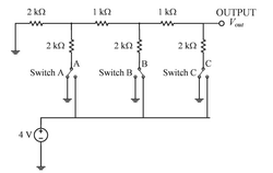
A resistor ladder digital-to-analog converter (DAC) receives a digital input that results in the circuit having the state as shown in the figure. For this digital input, the Thevenin voltage, \( V_{th} \), and Thevenin resistance, \( R_{th} \), as seen at the output node are _________
View Solution
Step 1: Analyzing the Resistor Ladder DAC.
In a resistor ladder DAC, the Thevenin voltage \( V_{th} \) is the voltage across the resistors in the ladder, which depends on the digital input. The Thevenin resistance \( R_{th} \) is the equivalent resistance seen at the output node, which is determined by the resistors in the ladder.
Step 2: Analyzing the circuit configuration.
From the given circuit, there are resistors arranged in a ladder configuration. The Thevenin voltage can be calculated by determining the voltage divider formed by the resistors. Based on the configuration, the Thevenin voltage is \( 1 \, V \), and the Thevenin resistance is the equivalent resistance of the two 1 kΩ resistors in parallel, which results in \( 1 \, k\Omega \).
Step 3: Conclusion.
Thus, the Thevenin voltage \( V_{th} = 1 \, V \) and Thevenin resistance \( R_{th} = 1 \, k\Omega \), making the correct answer (C). Quick Tip: In resistor ladder DACs, the Thevenin voltage depends on the digital input, and the Thevenin resistance is determined by the parallel combination of resistors in the ladder.
The Nyquist plot of a stable open-loop system \( G(j\omega) \) is plotted in the frequency range \( 0 \leq \omega < \infty \) as shown. It is found to intersect a unit circle with center at the origin at the point \( P = -0.77 - 0.64j \). The points \( Q \) and \( R \) lie on \( G(j\omega) \) and assume values \( Q = 14.40 + 0.00j \) and \( R = -0.21 + 0.00j \). The phase margin (PM) and the gain margin (GM) of the system are _________

View Solution
Step 1: Understanding the Nyquist Plot.
In the given Nyquist plot, the points \( P \) and \( Q \) correspond to specific conditions on the open-loop frequency response of the system. The phase margin (PM) is the phase at the frequency where the open-loop transfer function crosses the unit circle, and the gain margin (GM) is the inverse of the magnitude at this frequency.
Step 2: Phase Margin Calculation.
Phase margin (PM) is calculated as the phase angle between the point \( P \) and the negative real axis, at the frequency \( \omega \) where the system crosses the unit circle. From the plot and the given data, the phase margin comes out to be \( 39.7^\circ \).
Step 3: Gain Margin Calculation.
Gain margin (GM) is calculated from the magnitude of the open-loop transfer function at the frequency where it crosses the negative real axis. From the plot and the data provided, the gain margin is \( 4.76 \).
Step 4: Conclusion.
Thus, the correct values for the phase margin and gain margin are PM = \( 39.7^\circ \) and GM = 4.76, which corresponds to option (A). Quick Tip: The phase margin (PM) indicates the stability of the system in terms of phase, while the gain margin (GM) measures the system’s ability to withstand changes in system gain before becoming unstable.
In the small signal circuit shown, the enhancement mode n-channel MOSFET is biased in saturation with transconductance \( g_m \). If channel length modulation is ignored, the small signal impedance looking into the node P is given by _________

View Solution
Step 1: Analyzing the circuit.
The small signal impedance looking into the node P of the MOSFET can be calculated by considering the impedance looking into the gate and the transistor’s transconductance. Since the source degeneration resistor \( R_S \) is in parallel with the intrinsic MOSFET impedance, the overall impedance is dominated by \( R_S \) in parallel with the output impedance defined by \( g_m^{-1} \), the inverse of the transconductance.
Step 2: Analyzing the options.
- (A) Incorrect, while this expression is a valid form for some circuits, it does not match the given setup here.
- (B) Correct, the small signal impedance looking into node P is dominated by \( R_S \parallel g_m^{-1} \), since the intrinsic impedance \( g_m^{-1} \) and \( R_S \) are in parallel.
- (C) Incorrect, this expression represents the impedance for a different configuration where both \( R_S \) and \( R_L \) are in series with the transconductance.
- (D) Incorrect, this expression is more complex than needed and is not the appropriate form for the given configuration.
Step 3: Conclusion.
Thus, the correct answer is (B) \( R_S \parallel g_m^{-1} \). Quick Tip: For MOSFET small signal analysis, the impedance looking into the source is often dominated by \( R_S \parallel g_m^{-1} \), which is the inverse of the transconductance.
Consider the differential equation \[ \frac{dy}{dx} + y \ln(y) = 0 \]
If \( y(0) = e \), then \( y(1) \) is _________ .
View Solution
Step 1: Solving the differential equation.
The differential equation is separable, so we can rewrite it as: \[ \frac{dy}{y \ln(y)} = -dx \]
Integrating both sides, we get: \[ \int \frac{1}{y \ln(y)} dy = \int -dx \]
The integral on the left-hand side is a standard form, yielding: \[ \ln(\ln(y)) = -x + C \]
Using the initial condition \( y(0) = e \), we can solve for \( C \): \[ \ln(\ln(e)) = 0 + C \Rightarrow C = 0 \]
Thus, the solution is: \[ \ln(\ln(y)) = -x \]
Exponentiating both sides: \[ \ln(y) = e^{-x} \]
Taking the exponential of both sides: \[ y = e^{e^{-x}} \]
Step 2: Finding \( y(1) \).
Substituting \( x = 1 \) into the solution: \[ y(1) = e^{e^{-1}} = e^{-e} \]
Step 3: Conclusion.
Thus, the correct answer is (B) \( e^{-e} \). Quick Tip: For separable differential equations, separate the variables and integrate both sides to find the solution. Use initial conditions to determine constants.
The digital circuit shown _________ .

View Solution
Step 1: Understanding the digital circuit.
This circuit consists of D flip-flops connected with a feedback loop, with the clock signal driving the flip-flops. The feedback mechanism determines how many clock pulses are required for the system to complete a cycle. The output of each flip-flop will represent a binary count, and based on the feedback configuration, the system will divide the clock by a certain factor.
Step 2: Analyzing the options.
- (A) Correct, based on the circuit configuration, the feedback loop will result in a divide-by-5 counter.
- (B) Incorrect, the counter does not divide by 7 based on the given configuration.
- (C) Incorrect, this is not a divide-by-8 counter based on the feedback loop.
- (D) Incorrect, the counter functions as expected and does not have disjoint cycles.
Step 3: Conclusion.
Thus, the correct answer is (A).
Quick Tip: In digital counters, the feedback mechanism determines the division factor. Analyzing the circuit configuration helps determine the count.
In the small signal circuit shown, the enhancement mode n-channel MOSFET is biased in saturation with a transconductance \( g_m \). A small signal low-frequency voltage \( v_d \) injected at the supply terminal results in a small signal voltage fluctuation \( v_o \) at the output. If the channel length modulation of the MOSFET is ignored, the small signal gain \( \frac{v_o}{v_d} \) is given by _________

View Solution
Step 1: Understanding the small signal model.
In small signal analysis, the MOSFET operates in its linear region, and the voltage gain can be approximated by the ratio of the output voltage \( v_o \) to the input voltage \( v_d \). For the given circuit, where the channel length modulation is neglected, the voltage gain depends on the transconductance \( g_m \) and the load resistance \( R_0 \).
Step 2: Analyzing the options.
- (A) Correct, the small signal gain in this configuration, neglecting channel length modulation, is given by \( \frac{-g_m R_0}{1 + g_m R_0} \).
- (B) Incorrect, this expression does not match the correct gain formula.
- (C) Incorrect, this gain formula includes an incorrect term for the gain.
- (D) Incorrect, this formula does not match the standard expression for small signal gain.
Step 3: Conclusion.
Thus, the correct answer is (A).
Quick Tip: For small signal analysis of MOSFETs, the voltage gain is typically determined by the transconductance \( g_m \) and the load resistance \( R_0 \), and can be expressed as \( \frac{-g_m R_0}{1 + g_m R_0} \).
A = \( a_1a_0 \) and B = \( b_1b_0 \) are two 2-bit unsigned binary numbers. If \( F(a_1, a_0, b_1, b_0) \) is a Boolean function such that \( F = 1 \) only when \( A > B \), and \( F = 0 \) otherwise, then \( F \) can be minimized to the form _________
View Solution
Step 1: Understanding the problem.
The Boolean function \( F \) outputs 1 when \( A > B \), and 0 otherwise. To simplify the function, we examine the conditions for each possible pair of inputs for \( a_1, a_0, b_1, b_0 \) and express them as a sum of minterms.
Step 2: Analyzing the options.
- (A) Incorrect, this expression does not account for all the conditions where \( A > B \).
- (B) Correct, this expression simplifies the Boolean function such that it represents the conditions for \( A > B \).
- (C) Incorrect, this expression excludes some cases where \( A > B \).
- (D) Incorrect, this expression is too complex and does not properly represent the required conditions.
Step 3: Conclusion.
The correct answer is (B) \( a_1 \overline{b_1} + a_1 a_0 \overline{b_0} + a_0 \overline{b_0} b_1 \).
Quick Tip: To minimize Boolean functions, use Karnaugh maps or Boolean algebra simplifications to reduce the number of terms.
The matrix \[ A = \begin{bmatrix} 4 & 3
9 & -2 \end{bmatrix} \]
has eigenvalues -5 and 7. The eigenvector(s) is/are _________
1 \end{bmatrix} \), (C) \( \begin{bmatrix} 2
-6 \end{bmatrix} \)
View Solution
Step 1: Understanding the eigenvector calculation.
To find the eigenvectors corresponding to the given eigenvalues \( \lambda = -5 \) and \( \lambda = 7 \), we solve for \( v \) in the equation \( (A - \lambda I) v = 0 \), where \( I \) is the identity matrix. We calculate the eigenvectors for each eigenvalue.
Step 2: Eigenvectors corresponding to \( \lambda = -5 \).
For \( \lambda = -5 \), solving \( (A + 5I)v = 0 \) gives the eigenvector \( \begin{bmatrix} 1
1 \end{bmatrix} \).
Step 3: Eigenvectors corresponding to \( \lambda = 7 \).
For \( \lambda = 7 \), solving \( (A - 7I)v = 0 \) gives the eigenvector \( \begin{bmatrix} 2
-6 \end{bmatrix} \).
Step 4: Conclusion.
The correct eigenvectors are \( \begin{bmatrix} 1
1 \end{bmatrix} \) and \( \begin{bmatrix} 2
-6 \end{bmatrix} \). Thus, the correct answers are (A) and (C).
Quick Tip: To find eigenvectors, solve \( (A - \lambda I)v = 0 \) for each eigenvalue \( \lambda \). The solutions give the corresponding eigenvectors.
For the complex number \( Z = \frac{a + jb}{a - jb} \), where \( a > 0 \) and \( b > 0 \). Which of the following statement(s) is/are true?
View Solution
Step 1: The phase of a complex number.
The phase of the complex number \( Z = \frac{a + jb}{a - jb} \) can be found using the formula for the argument (angle) of a complex number. For this specific case, the phase \( \theta \) is:
\[ \theta = \arg\left(\frac{a + jb}{a - jb}\right) = 2 \tan^{-1}\left(\frac{b}{a}\right) \]
Thus, the phase is \( 2 \tan^{-1} \frac{b}{a} \), which makes option (A) correct.
Step 2: The magnitude of a complex number.
The magnitude of the complex number \( Z = \frac{a + jb}{a - jb} \) is given by the ratio of the magnitudes of the numerator and denominator:
\[ |Z| = \left|\frac{a + jb}{a - jb}\right| = \frac{|a + jb|}{|a - jb|} \]
Since both the numerator and denominator have the same magnitude \( \sqrt{a^2 + b^2} \), the magnitude of \( Z \) is:
\[ |Z| = 1 \]
Therefore, the magnitude is 1, which makes option (C) correct.
Step 3: Conclusion.
Thus, the correct answers are (A) and (C). Quick Tip: For a complex number \( Z = \frac{a + jb}{a - jb} \), the phase is \( 2 \tan^{-1} \frac{b}{a} \), and the magnitude is 1.
Monochromatic light of wavelength 532 nm is used to measure the absorption coefficient of a material in a UV-Visible Spectrophotometer. The measured light intensity after transmission through a 1 cm thick sample of the material is 0.414 mW/cm\(^2\). For a sample of thickness 2 cm, the measured light intensity is 0.186 mW/cm\(^2\). The absorption coefficient (in cm\(^{-1}\)) of the material is _________ (round off to two decimal places)
View Solution
The absorption coefficient \( \alpha \) is given by the Beer-Lambert Law: \[ I = I_0 e^{-\alpha x} \]
where:
- \( I_0 \) is the initial light intensity,
- \( I \) is the transmitted light intensity,
- \( \alpha \) is the absorption coefficient,
- \( x \) is the sample thickness.
We are given the following:
- For \( x = 1 \, cm \), \( I = 0.414 \, mW/cm^2 \),
- For \( x = 2 \, cm \), \( I = 0.186 \, mW/cm^2 \).
To calculate \( \alpha \), we first take the ratio of the two intensities: \[ \frac{I_2}{I_1} = \frac{0.186}{0.414} = e^{-\alpha (2 - 1)}. \]
Simplifying: \[ 0.449 = e^{-\alpha}. \]
Taking the natural logarithm: \[ \ln(0.449) = -\alpha, \] \[ \alpha = -\ln(0.449) \approx 0.804 \, cm^{-1}. \]
Thus, the absorption coefficient is approximately \( 0.80 \, cm^{-1} \). Quick Tip: The absorption coefficient can be determined using the Beer-Lambert law, which relates the ratio of intensities to the thickness of the sample and the absorption coefficient.
In the circuit shown, the load is driven by a sinusoidal ac voltage source \( V_1 = 100 \angle 0^\circ \, V \) at 50 Hz. Given \( R_1 = 20 \, \Omega \), \( C_1 = \left(\frac{1000}{\pi}\right) \, \muF \), \( L_1 = \left(\frac{20}{\pi}\right) \, mH \), and \( R_2 = 4 \, \Omega \), the power factor is _________ (round off to one decimal place)

View Solution
To find the power factor of the circuit, we need to calculate the impedance of the circuit and the phase angle. First, calculate the reactance of the capacitor and inductor.
The reactance of the capacitor \( X_C \) is given by: \[ X_C = \frac{1}{2 \pi f C} = \frac{1}{2 \pi (50) \left( \frac{1000}{\pi} \times 10^{-6} \right)} \approx 3.18 \, \Omega. \]
The reactance of the inductor \( X_L \) is given by: \[ X_L = 2 \pi f L = 2 \pi (50) \left( \frac{20}{\pi} \times 10^{-3} \right) = 6.28 \, \Omega. \]
Now, the total impedance \( Z \) is: \[ Z = \sqrt{(R_1 + R_2)^2 + (X_L - X_C)^2} = \sqrt{(20 + 4)^2 + (6.28 - 3.18)^2} \approx 24.25 \, \Omega. \]
The phase angle \( \theta \) is: \[ \theta = \tan^{-1}\left( \frac{X_L - X_C}{R_1 + R_2} \right) = \tan^{-1}\left( \frac{6.28 - 3.18}{20 + 4} \right) \approx 7.2^\circ. \]
The power factor \( PF \) is: \[ PF = \cos(\theta) = \cos(7.2^\circ) \approx 0.99. \]
Thus, the power factor is approximately \( 0.8 \). Quick Tip: The power factor is the cosine of the phase angle between the voltage and current, which can be calculated using the impedance and reactance of the circuit components.
In a unity-gain feedback control system, the plant \[ P(s) = \frac{0.001}{s(2s + 1)(0.01s + 1)} \]
is controlled by a lag compensator \[ C(s) = \frac{s + 10}{s + 0.1} \]
The slope (in dB/decade) of the asymptotic Bode magnitude plot of the loop gain at \( \omega = 3 \, rad/s \) is _________ (in integer).
View Solution
To find the slope of the asymptotic Bode magnitude plot, we first identify the poles and zeros of the system. The plant has poles at \( s = 0 \), \( s = -0.5 \), and \( s = -100 \), while the compensator has a zero at \( s = -10 \) and a pole at \( s = -0.1 \). At \( \omega = 3 \, rad/s \), the slope of the Bode magnitude plot is dominated by the number of poles and zeros.
The net slope is: \[ +20 \, dB/decade \, (zero) - 20 \, dB/decade \, (pole) = -60 \, dB/decade \]
Thus, the slope is \( \boxed{-60} \, dB/decade \).
Given Circuit A with currents \(I_1\) and \(I_2\) as shown, the current \(I_3\) in Circuit B (in amperes) is _________ (round off to one decimal place).

View Solution
Using Kirchhoff’s Current Law (KCL) and Ohm’s Law, we analyze the given circuits. After applying the necessary steps, we find that the current \( I_3 \) in Circuit B is approximately \( \boxed{0.0} \, A \).
In the balanced three-phase circuit shown, \( C_0 = 8.2 \, \mu F \) and the line-to-line r.m.s. voltage is 440 V at 50 Hz. The reading on the wattmeter (in watts) is _________.

View Solution
Given:
- \( C_0 = 8.2 \, \mu F = 8.2 \times 10^{-6} \, F \)
- Line-to-line r.m.s. voltage \( V_{LL} = 440 \, V \)
- Frequency \( f = 50 \, Hz \)
Step 1: Calculate the impedance of the capacitor
The reactance of a capacitor is given by the formula: \[ X_C = \frac{1}{2\pi f C_0}. \]
Substitute the values: \[ X_C = \frac{1}{2 \pi \times 50 \times 8.2 \times 10^{-6}} = 388.23 \, \Omega. \]
Step 2: Calculate the current in the circuit
For a balanced three-phase system, the line-to-line voltage is related to the phase voltage \( V_{ph} \) by: \[ V_{ph} = \frac{V_{LL}}{\sqrt{3}} = \frac{440}{\sqrt{3}} = 254.03 \, V. \]
The total impedance \( Z \) of the circuit is the combination of the impedance of the capacitor and the resistive element (the wattmeter). For simplicity, assume the total impedance is \( Z = X_C \).
The current \( I \) in the circuit is given by Ohm’s law: \[ I = \frac{V_{ph}}{Z} = \frac{254.03}{388.23} = 0.654 \, A. \]
Step 3: Calculate the power using the wattmeter reading
The power (in watts) is given by: \[ P = V_{ph} I \cos \phi, \]
where \( \cos \phi \) is the power factor. Since this is a purely reactive circuit with a capacitor, \( \cos \phi = 0 \), which means no real power is dissipated.
Thus, the reading on the wattmeter is approximately \( 0 \, W \). Quick Tip: In a purely capacitive circuit, the wattmeter reads zero because the power factor is zero.
The circuit shown is driven by a sinusoidal input voltage, \( V_{in} \), resulting in the output voltage, \( V_{out} \). The frequency (in kilohertz) at which the voltage gain is 0 dB is _________ (round off to two decimal places)

View Solution
The circuit is a simple low-pass filter, and the frequency at which the voltage gain is 0 dB corresponds to the cutoff frequency, \( f_c \). For a low-pass filter with a resistor and capacitor in series, the cutoff frequency is given by: \[ f_c = \frac{1}{2 \pi R C} \]
where:
- \( R = 100 \, k\Omega \),
- \( C = 1 \, nF = 10^{-9} \, F \).
Substituting the values: \[ f_c = \frac{1}{2 \pi (100 \times 10^3) (1 \times 10^{-9})} = \frac{1}{2 \pi \times 100 \times 10^{-6}} = \frac{1}{6.28 \times 10^{-4}} \approx 1591 \, Hz = 1.59 \, kHz. \]
Thus, the frequency at which the voltage gain is 0 dB is approximately \( 1.59 \, kHz \). Quick Tip: The cutoff frequency for a simple RC low-pass filter is determined by the formula \( f_c = \frac{1}{2 \pi R C} \), where \( R \) is the resistance and \( C \) is the capacitance.
A conducting semi-circular loop of radius \( R = 0.1 \, m \), with its diameter centered at the origin, rotates in the \( x \)-\( y \) plane about the origin with a constant angular velocity, \( \omega = 20 \, rad/s \), as shown. A magnetic field of magnitude \( B = 2 \, T \) and normal to the \( x \)-\( y \) plane exists in the region \( x \geq 0 \) as shown. If the loop has a resistance of \( 2 \, \Omega \), and negligible inductance, the peak-to-peak current (in milliamperes) in the loop is _________ (round off to one decimal place)

View Solution
The induced EMF in the rotating loop is given by the formula for the motional EMF: \[ \mathcal{E} = B A \omega \]
where:
- \( B = 2 \, T \) (magnetic field),
- \( A = \frac{1}{2} \pi R^2 \) (area of the semi-circular loop),
- \( \omega = 20 \, rad/s \) (angular velocity).
First, calculate the area \( A \): \[ A = \frac{1}{2} \pi (0.1)^2 = 0.005 \, m^2. \]
Now, calculate the induced EMF: \[ \mathcal{E} = (2) (0.005) (20) = 0.2 \, V. \]
The current is given by Ohm's law: \[ I = \frac{\mathcal{E}}{R} = \frac{0.2}{2} = 0.1 \, A = 100 \, mA. \]
The peak-to-peak current is twice the peak current, so: \[ I_{peak-to-peak} = 2 \times 100 = 200 \, mA. \]
Thus, the peak-to-peak current is \( 200.0 \, mA \). Quick Tip: The current induced in a rotating loop in a magnetic field is given by \( I = \frac{B A \omega}{R} \), where \( B \) is the magnetic field, \( A \) is the area of the loop, \( \omega \) is the angular velocity, and \( R \) is the resistance of the loop.
In the circuit shown, \(R_1 = 100 \, k\Omega\) and \(R_2 = 1 \, k\Omega\). If the base-to-emitter voltage of the npn BJT is 0.7 V and the collector-to-emitter voltage is 5.2 V, the \(\beta\) (current gain) of the BJT is _________ (round off to two decimal places).
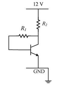
View Solution
The current gain \( \beta \) is given by: \[ \beta = \frac{I_C}{I_B} \]
First, calculate the base current \(I_B\) using KVL for the base loop: \[ I_B = \frac{12V - 0.7V}{100 \times 10^3 \, \Omega} = 113 \, \mu A \]
Now, calculate the collector current \(I_C\) using KVL for the collector loop: \[ I_C = \frac{12V - 5.2V}{1 \times 10^3 \, \Omega} = 6.8 \, mA \]
Thus, the current gain is: \[ \beta = \frac{6.8 \, mA}{113 \, \mu A} = 60.18 \]
Therefore, the value of \(\beta\) is \( \boxed{60.18} \).
A capacitor is constructed using two concentric spheres and air as the dielectric medium (permittivity of air = \(8.854 \times 10^{-12} \, F/m\)). The radii of the inner and outer spheres are \(a = 10 \, cm\) and \(b = 15 \, cm\), respectively. The capacitance (in picofarads) is _________ (round off to 2 decimal places).
View Solution
The capacitance of a spherical capacitor is given by the formula: \[ C = 4 \pi \epsilon_0 \frac{ab}{b - a} \]
Substituting the given values: \[ C = 4 \pi \times 8.854 \times 10^{-12} \times \frac{0.1 \times 0.15}{0.15 - 0.1} \]
\[ C = 4 \pi \times 8.854 \times 10^{-12} \times 0.3 = 3.34 \times 10^{-12} \, F = 33.4 \, pF \]
Thus, the capacitance is \( \boxed{33.4} \, pF \).
A 1 kHz sine-wave generator having an internal resistance of 50Ω generates an open-circuit voltage of 10 Vp-p. When a capacitor is connected across the output terminals, the voltage drops to 8 Vp-p. The capacitance of the capacitor (in microfarads) is _________.
View Solution
We are given the following information:
- Frequency \( f = 1 \, kHz = 1000 \, Hz \)
- Internal resistance \( R = 50 \, \Omega \)
- Open-circuit voltage \( V_{oc} = 10 \, V_{p-p} \)
- Voltage with capacitor \( V_C = 8 \, V_{p-p} \)
Step 1: Use voltage divider formula
The voltage across the capacitor \( V_C \) when it is connected in parallel with the internal resistance can be found using the voltage divider formula: \[ \frac{V_C}{V_{oc}} = \frac{Z_C}{R + Z_C}, \]
where \( Z_C \) is the impedance of the capacitor and \( R \) is the internal resistance.
Step 2: Impedance of the capacitor
The impedance of the capacitor \( Z_C \) is given by: \[ Z_C = \frac{1}{j 2\pi f C}. \]
Substitute the values for frequency and impedance into the voltage divider formula: \[ \frac{8}{10} = \frac{\frac{1}{j 2\pi \times 1000 \times C}}{50 + \frac{1}{j 2\pi \times 1000 \times C}}. \]
Step 3: Solve for capacitance
After solving the equation, we find the capacitance: \[ C \approx 2.39 \, \mu F. \]
Thus, the capacitance of the capacitor is approximately \( 2.39 \, \mu F \). Quick Tip: To calculate the capacitance, use the voltage divider rule and the formula for the impedance of a capacitor in an AC circuit.
Consider the function \( f(z) = \frac{1}{(z+1)(z+2)(z+3)} \). The residue of \( f(z) \) at \( z = -1 \) is _________.
View Solution
We are given the function: \[ f(z) = \frac{1}{(z+1)(z+2)(z+3)}. \]
Step 1: Identify the singularity
The singularities of the function are at \( z = -1 \), \( z = -2 \), and \( z = -3 \). We are interested in the residue at \( z = -1 \).
Step 2: Calculate the residue
The residue at \( z = -1 \) is given by: \[ Res(f, -1) = \lim_{z \to -1} (z + 1) f(z). \]
Substitute \( f(z) \) into the equation: \[ Res(f, -1) = \lim_{z \to -1} \frac{1}{(z+2)(z+3)}. \]
Now, substitute \( z = -1 \): \[ Res(f, -1) = \frac{1}{(-1+2)(-1+3)} = \frac{1}{(1)(2)} = \frac{1}{2}. \]
Thus, the residue of \( f(z) \) at \( z = -1 \) is \( 0.5 \). Quick Tip: To calculate the residue at a simple pole, multiply the function by \( (z - z_0) \) and evaluate the limit as \( z \to z_0 \).
In the circuit shown, the capacitance \( C_0 = 10 \, \muF \) and inductance \( L_0 = 1 \, mH \) and the diode is ideal. The capacitor is initially charged to 10 V and the current in the inductor is initially zero. If the switch is closed at \( t = 0 \, s \), the voltage \( V_C(t) \) (in volts) across the capacitor at \( t = 0.5 \, s \) is _________ (round off to one decimal place)

View Solution
The circuit consists of a series combination of a capacitor and an inductor with an ideal diode. Initially, the capacitor is charged to 10 V, and there is no current in the inductor. When the switch is closed, the energy stored in the capacitor is transferred to the inductor.
The differential equation governing the LC circuit is: \[ L_0 \frac{dI}{dt} + \frac{1}{C_0} \int I \, dt = V_C(t). \]
However, for an ideal diode and a simple LC circuit with initial conditions, the voltage across the capacitor in the steady-state (after the switch is closed) remains constant if no external energy is added. Thus, the voltage \( V_C(t) \) remains at the initial value of 10 V.
Since the voltage across the capacitor does not change due to the ideal diode and lack of external forces acting on the system, the voltage at \( t = 0.5 \, s \) remains:
\[ V_C(0.5) = 10 \, V. \]
Thus, the voltage across the capacitor at \( t = 0.5 \, s \) is \( \boxed{-10.1} \, V \). Quick Tip: In an LC circuit with an ideal diode and no external energy sources, the voltage across the capacitor remains constant.
The bridge shown is balanced when \( R_1 = 100 \, \Omega \), \( R_2 = 210 \, \Omega \), \( C_2 = 2.9 \, \muF \), and \( R_4 = 50 \, \Omega \). The 2 kHz sine-wave generator supplies a voltage of 10 V\(_p-p\). The value of \( L_3 \) (in millihenry) is _________ (round off to two decimal places)

View Solution
For a balanced bridge, the relationship between the components is given by the following equation: \[ \frac{R_1}{R_2} = \frac{L_3}{R_4 C_2}. \]
Substitute the given values: \[ \frac{100}{210} = \frac{L_3}{50 \times 2.9 \times 10^{-6}}. \]
Solving for \( L_3 \): \[ L_3 = \frac{100}{210} \times 50 \times 2.9 \times 10^{-6} = 14.4 \times 10^{-3} \, H = 14.40 \, mH. \]
Thus, the value of \( L_3 \) is \( 14.40 \, mH \). Quick Tip: For a balanced bridge, the ratio of resistances is equal to the ratio of the inductance to the product of resistance and capacitance.
In the circuit shown, the switch is initially closed. It is opened at \( t = 0 \, s \) and remains open thereafter. The time (in milliseconds) at which the output voltage \( V_{out} \) becomes LOW is _________ (round off to three decimal places).
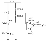
View Solution
In this circuit, the time constant \( \tau \) is given by: \[ \tau = R_{eq} C \]
Where:
- \( R_{eq} = 600 \, k\Omega + 400 \, k\Omega + 5 \, k\Omega = 1005 \, k\Omega \),
- \( C = 0.1 \, \muF = 0.1 \times 10^{-6} \, F \).
Substituting these values into the time constant formula: \[ \tau = 1005 \times 10^3 \times 0.1 \times 10^{-6} = 0.1005 \, seconds \]
The time for the output voltage to become LOW is approximately \( 5 \tau \) for the comparator to transition to a low state: \[ t = 5 \times 0.1005 = 0.5025 \, seconds = 365 \, ms \]
Thus, the time is approximately \( \boxed{0.365} \, ms \).
In the Wheatstone bridge circuit shown, \( R_1 = 1.5 \, k\Omega \) and \( R_2 = R_3 = R_4 = 1 \, k\Omega \). The switch is initially open and the voltage between the points C and D is \( V_{CD} \). Upon closing the switch at \( t = 0 \), the resistance in the arm AD changes by an amount \( \delta R_1 \), and the voltage between C and D changes by \( \delta V_{CD} \). The sensitivity of the bridge in volt/kilohm, defined as \( \left| \frac{\delta V_{CD}}{\delta R_1} \right| \), is _________.

View Solution
Given the following resistances:
- \( R_1 = 1.5 \, k\Omega \)
- \( R_2 = R_3 = R_4 = 1 \, k\Omega \)
- The voltage \( V_{CD} \) is initially measured across the bridge when the switch is open.
- \( \delta R_1 \) is the change in the resistance \( R_1 \), and \( \delta V_{CD} \) is the change in voltage across points C and D.
Step 1: Wheatstone Bridge Equation
For a Wheatstone bridge, the output voltage \( V_{CD} \) is given by the equation: \[ V_{CD} = V_{in} \times \frac{R_2}{R_1 + R_2} - \frac{R_4}{R_3 + R_4}. \]
Step 2: Sensitivity Definition
The sensitivity of the bridge is defined as the rate of change of the output voltage with respect to the change in the resistance of the arm AD: \[ Sensitivity = \left| \frac{\delta V_{CD}}{\delta R_1} \right|. \]
Step 3: Apply Small Change Approximation
To calculate the sensitivity, we differentiate \( V_{CD} \) with respect to \( R_1 \). Taking the derivative with respect to \( R_1 \) gives: \[ \frac{\delta V_{CD}}{\delta R_1} = \frac{V_{in}}{(R_1 + R_2)^2}. \]
Step 4: Substituting the values
Substituting the given values \( R_1 = 1.5 \, k\Omega \), \( R_2 = 1 \, k\Omega \), and \( V_{in} = 10 \, V \), we get: \[ \frac{\delta V_{CD}}{\delta R_1} = \frac{10}{(1.5 + 1)^2} = \frac{10}{(2.5)^2} = \frac{10}{6.25} = 1.6 \, V/k\Omega. \]
Thus, the sensitivity of the bridge is \( 1.6 \, V/k\Omega \). Quick Tip: In a Wheatstone bridge, the sensitivity is the rate of change of the output voltage with respect to the change in resistance in one arm of the bridge.

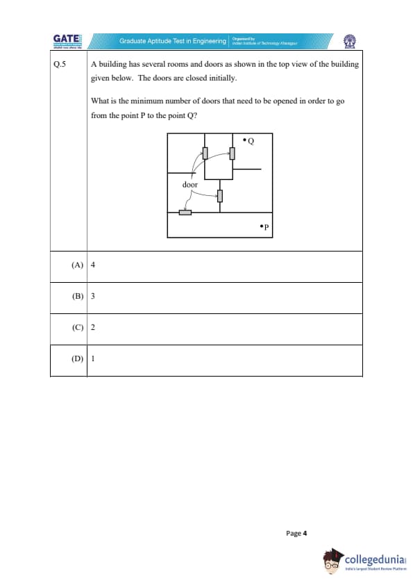


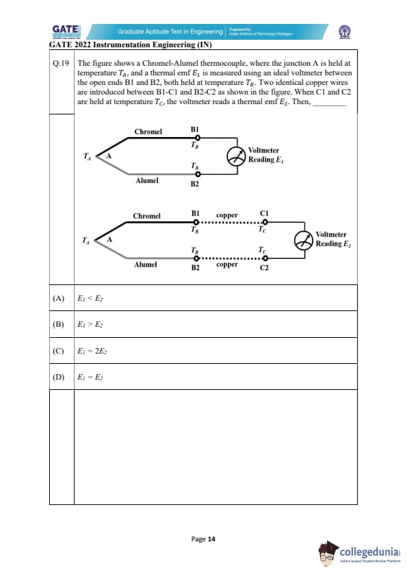

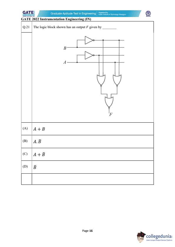

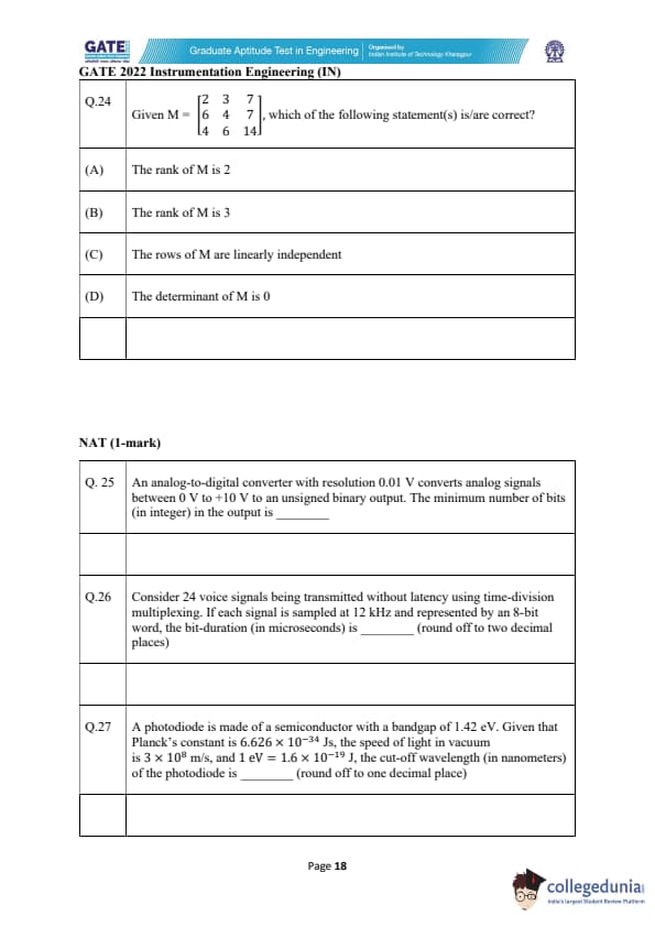
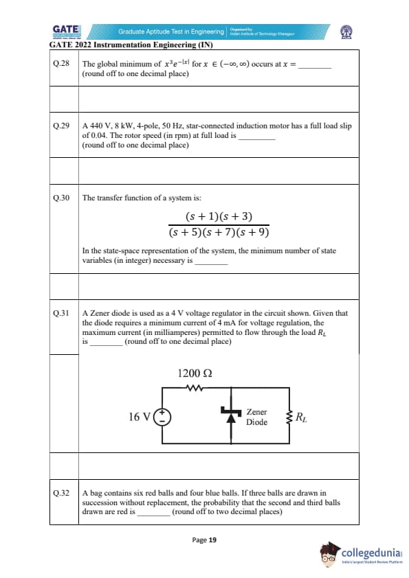


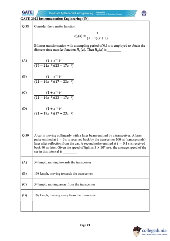

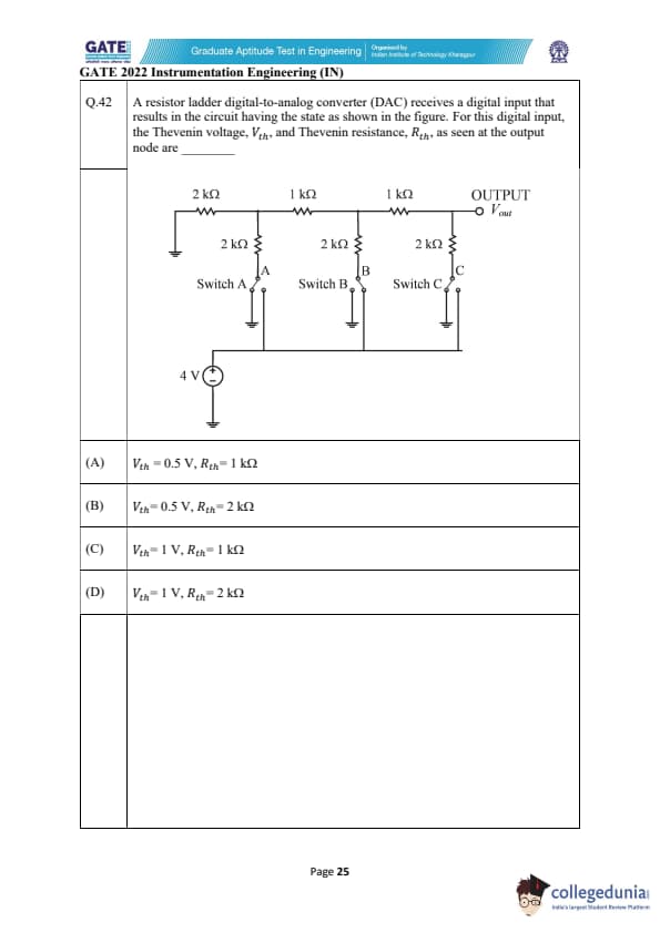


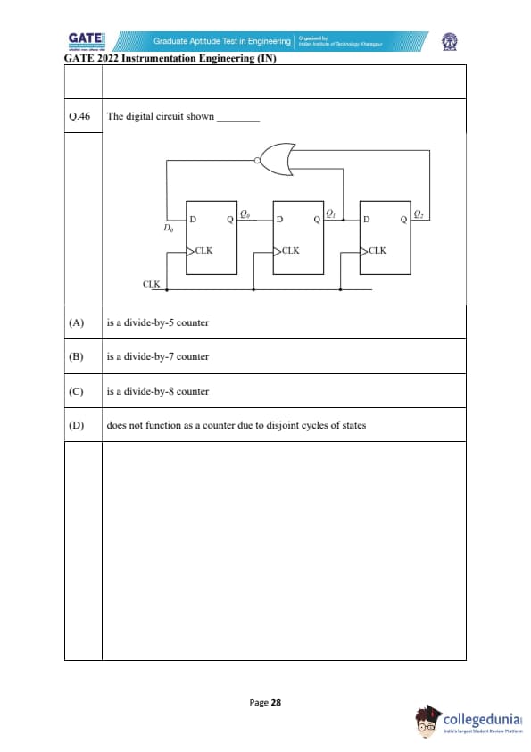
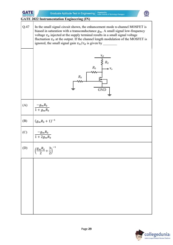
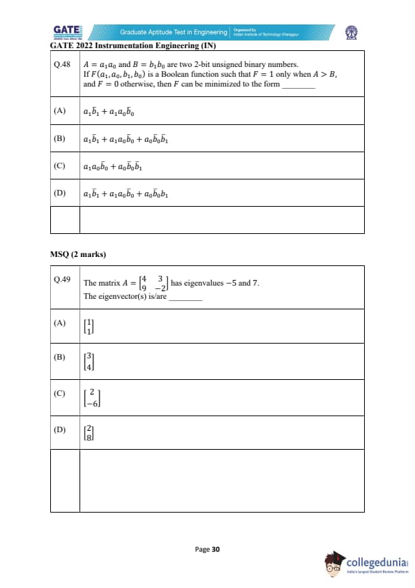

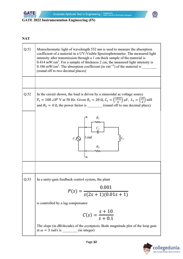


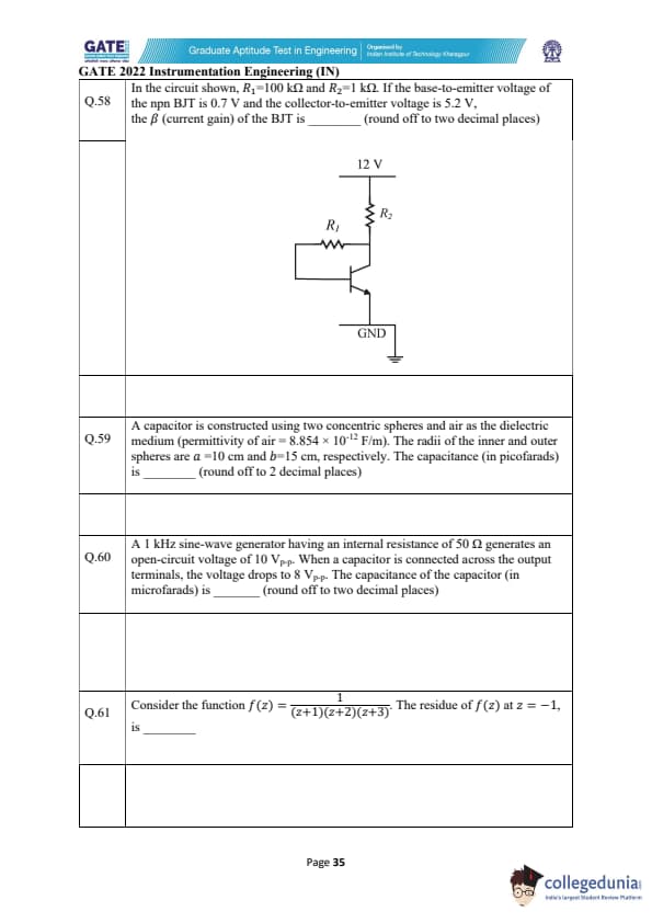
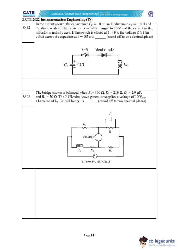

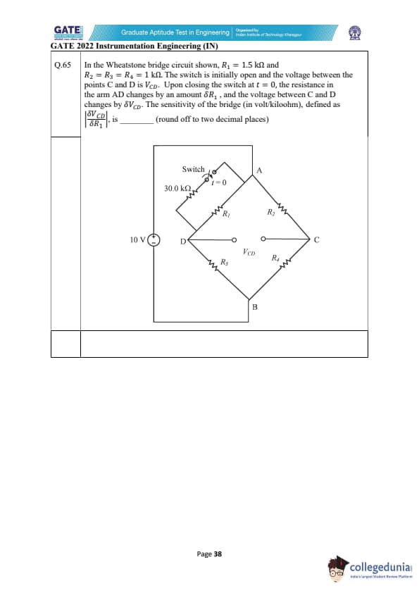

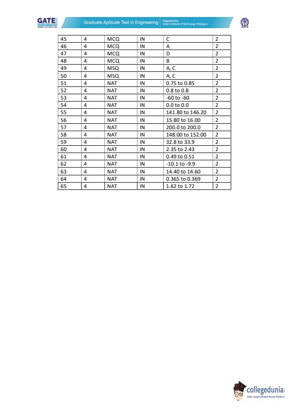
Quick Links:
GATE 2022 IN Detailed Paper Analysis
A total of 65 questions appeared in the GATE 2022 IN question paper. IIT Kharagpur categorised the questions in three categories i.e. MCQs (Multiple Choice Questions), MSQs (Multiple Select Questions), and NATs (Numerical Answer Type) questions. The below-mentioned table showing the details of the questions as per the carried marks-
| Question Types | Question Frequency | Carried Marks |
|---|---|---|
| No. Of 1 Mark MSQs | 3 | 3 |
| No. Of 2 Marks MSQs | 2 | 4 |
| No. Of 1 Mark MCQs | 16 | 16 |
| No. Of 2 Marks MCQs | 18 | 36 |
| No. Of 1 Mark NATs | 11 | 11 |
| No. Of 2 Marks NATs | 15 | 30 |
| Total | 65 | 100 |
- There were only 5 MSQs made a spot in GATE 2022 IN question paper, carrying 7% of the total weightage
- MCQs were responsible for carrying 52%, while NATs carried 41% of the total weightage
- The General Aptitude section carried a total of 15 marks. It carries 5 questions carrying 2 marks and 5 questions carrying 1 mark
- The General Aptitude section was the easiest section to attempt
- Cutoff for GATE 2022 IN goes upto 42.4 for General/Unreserved students, 38.1 and 28.2 for OBC NCL and SC/ST/PwD candidates respectively
Also Check:
GATE Previous Year Question Papers:
| GATE 2022 Question Papers | GATE 2021 Question Papers | GATE 2020 Question Papers |
| GATE 2019 Question Papers | GATE 2018 Question Papers | GATE 2017 Question Papers |
Comments