


Content Curator
Alternating current (AC) is an electric current, the magnitude of which changes with time and polarity reverses periodically.
- The flow of charged particles, such as electrons or ions, traveling through an electrical conductor or space is referred to as an electric current.
- It is defined as the net rate of charge flow through a surface.
- Electric currents are of two types i.e. Alternating current (AC) and Direct current (DC).
- In AC, the magnitude and polarity of the current change with time.
- In DC, the magnitude and polarity remain the same over time.
Key Terms: AC Voltage, Transformers, LC Oscillations, Electrical circuit, DC circuit, Phasor, Sine wave, Capacitance, Inductance, Resistance, Electric power, Electric Energy
Alternating Current
[Click Here for Sample Questions]
An alternating current is a current that changes amplitude and polarity at regular time intervals.
- It can also be described as an electrical current that changes or reverses direction regularly as compared to Direct Current (DC), which constantly flows in a single direction.
- The electricity in power lines and your wall outlet isn't steady.
- It actually changes direction and strength over and over again, like a wave in the ocean.
- This is called alternating current.
- The number of cycles completed in one second is known as the frequency of the alternating current.
- The time taken to complete one cycle is known as the time period of the alternating current.
The sinusoidal alternating current is expressed as
\(I=I_o\sin\omega t\)
Where
- Io is the maximum value, peak value, or amplitude of AC
- ω is the angular frequency

Discover about Alternating Current Pdf:
Alternating Current Notes Pdf Explanation


Advantages of Alternating Current
[Click Here for Previous Year Questions]
The advantages of alternating current are
- The generation, transmission, and distribution of alternating current are more economical than that of direct current.
- Ac travels on the surface of the conductor, so costly conducting materials can be saved for long-distance transmission by using an inner core of cheaper materials.
- AC can reach distant places without much loss of electric power.
- It can be easily convertible into DC using a rectifier.
- AC machines are small-sized, have a longer life, and, are easy to use.
Also Read:
Production of Alternating Current
[Click Here for Sample Questions]
Alternators, also known as AC generators or Dynamos can be used to produce or generate alternating current.
- However, alternating current can be created using a variety of ways using different circuits.
- A basic single-coil AC generator, which consists of two-pole magnets and a single rectangular loop of wire, is one of the most common or simple means of generating AC.
- In this configuration, the AC generator converts mechanical energy into electrical energy using Faraday's law of electromagnetic induction.
Meanwhile, three wires are used to supply alternating current to various pieces of equipment. These are their names:
- The hot wire is used to transmit power.
- The neutral wire, which is grounded, serves as a return channel for the current in the hot wire.
- The third wire, which also connects to the earth, is attached to the metallic parts of the equipment, mainly to eliminate the risk of electric shock.
Applications of Alternating Current
[Click Here for Previous Year Questions]
The following are the applications of alternating current
- AC is the most common type of electricity found in many devices.
- Alternating current signals include audio signals, radio signals, and so forth.
- Alternating current has a significant benefit over direct current in that it can transport electricity across long distances with minimum energy loss.
- AC is commonly used in homes and offices since generating and transmitting AC across large distances is easier.
- Meanwhile, using transformers, AC may be easily converted to and from high voltages.
- AC can also power electric motors, transforming electrical energy into mechanical energy.
- AC is also used in major appliances such as refrigerators, dishwashers, and other equipment.
Average and RMS values of AC
[Click Here for Sample Questions]
The mean or average value of alternating current is the value of steady current which sends the same amount of charge through a circuit in a certain time interval as is sent by an AC through the same circuit in half cycle.
The formula for the average value of AC is given by
\(I_{av}=0.637\ I_o\)
Where Io is the maximum value of current.
The root mean square value (RMS value) of AC is defined as that steady current that produces the same amount of heat in a conductor in a certain time interval as is produced by the AC in the same conductor during a full cycle.
The formula for the RMS value of AC is given by
\(I_{rms}= \frac {I_o}{\sqrt 2}=0.707\ I_o\)
Phasor Diagram
[Click Here for Previous Year Questions]
Phasor is a rotating vector that represents a quantity varying sinusoidally with time.
- Rotation of a phasor treated as antilock with an angular speed ω.
- The graphical way of representing the magnitude and directional relationship between two or more alternating quantities is known as the Phasor diagram.
- The Phase difference is used to describe the difference between two alternating quantities.

AC Voltage Applied To A Resistor
[Click Here for Sample Questions]
The voltage that changes its direction every half cycle is called alternating voltage and the current flowing in the circuit at that time is known as alternating current.
- The alternating current(AC) follows the sine function which changes its polarity concerning time.
- Most electrical devices operate on an AC voltage.
- AC voltage is preferable in the circuits because it can be easily and efficiently converted into another voltage using a transformer.
- Resistance is a substance that produces obstructions in the flow of electric current.
- It is usually denoted by R and its SI unit is Ohm.

AC Voltage Applied To An Inductor
[Click Here for Previous Year Questions]
AC Voltage Applied to an Inductor implies an AC circuit that consists only of an inductor of inductance L which is connected to an AC source.
The AC voltage across the source is
V = Vm sin (ωt)
The changing current output of the AC source gives a back emf in the coil of magnitude which is given by
\(V_L=L \frac{di}{dt}\)
Here, we will learn more about the functioning of an electric circuit where we will have an inductor and an AC voltage V which is represented by “~”.

AC Voltage Applied To A Capacitor
[Click Here for Previous Year Questions]
In a DC circuit where the voltage source is connected to a capacitor, the current flows for a short period until the capacitor is charged.
- The charge accumulates on the capacitor plates and the voltage across these plates also increases, thus opposing the current.
- In simple terms, a capacitor in a DC circuit limits/opposes the current while it charges.
- Once the capacitor is fully charged, the circuit falls back to zero.
- Although the capacitor regulates the current, it does not completely obstruct the flow of charge.
- The capacitor alternatively charges and discharges each time the current reverses half-cycle.

AC Voltage Applied To A Series LCR Circuit
[Click Here for Sample Questions]
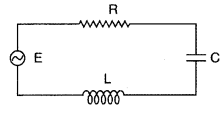
An LCR circuit, also known as a tuned or resonant circuit, refers to an electrical circuit that includes an inductor L, a capacitor C, and a resistor R which are connected in series so that the same amount of current flows in the circuit.
Here, an alternating current or AC generator or dynamo can be used as an AC voltage source.

Here
- R is the resistance of the resistor
- Lis the inductance of the inductor
- C is the capacitance of the capacitor
- V is the applied voltage
LC Oscillations Circuit
[Click Here for Previous Year Questions]
When a charged capacitor is connected to an inductor in the circuit, the electric current in the circuit and the charge on the capacitor undergo oscillations which are known as LC Oscillations.
- A circuit containing an inductor and a capacitor in parallel is called a Tank circuit.
- This circuit gives rise to oscillations called LC oscillations.
The frequency of the LC oscillation is given by
\(f=\frac{1}{2\pi \sqrt{LC}}\)
Where
- L is the inductance
- C is the capacitance

Transformers
[Click Here for Sample Questions]
As the name suggests, a transformer is a device used in power transmission to change the AC voltage without changing the frequency between the circuits.
- It can be used to increase (Step-up) or decrease (Step-down) the source voltage.
- It only works with the AC voltage.
- It works on the principle of electromagnetic induction and mutual induction.
- Transformers play a foundational role in the functioning of modern appliances and have a wide range of applications.

Important Topics for JEE MainAs per JEE Main;2024 Session 1, important topics included in the chapter Alternating Current are as follows:
|
Things to Remember
- Direct Current is that which does not change direction with time.
- The type of electric current that changes periodically with time is known as Alternating current.
- Alternators, also known as AC generators or Dynamos can be used to produce or generate alternating current.
- The graphical way of representing the magnitude and directional relationship between two or more alternating quantities is known as the Phasor diagram.
- When a charged capacitor is connected to an inductor in the circuit, the electric current in the circuit and the charge on the capacitor undergo oscillations which are known as LC Oscillations.
- A transformer is a device used in power transmission to change the AC voltage without changing the frequency between the circuits.
- A transformer works on the principle of electromagnetic induction.
Also Read:
Previous Year Questions
- RMS value of AC is _______ of the peak value… [VITEEE 2006]
- The instantaneous values of alternating current and voltages in a circuit... [JIPMER 2003]
- The average power dissipated in the A.C. circuit is 2 watts. If a current... [KCET 2014]
- An alternating voltage of 220 V, 50 Hz frequency is applied across... [VITEEE 2018]
- An inductive circuit contains a resistance of 10 Ω and... [VITEEE 2011]
- An AC supply gives 30 Vrms which is fed on... [JIPMER 2003]
- In the circuit shown, the symbols have their usual meanings. The cell has emf E….[BITSAT 2018]
- An electrical cable having a resistance of 0.2Ω delivers…. [WBJEE 2009]
- A coil of inductance 8.4 mH and resistance 6Ω is connected to a 12 V battery. The current in the coil is 1A at approximately the time….[JEE Advance 1999]
- A coil of resistance 10Ω and inductance 5H is connected to….[VITEEE 2011]
- the efficiency of the transformer is approximately….[NEET 2007]
- For a coil having L = 2 mH, current flow through it is ….[NEET 2001]
- A coil has resistance 30 ohm and inductive reactance 20 ohm at 50Hz frequency….[NEET 2011]
- A coil is self-inductance L is connected in series with a bulb B and an AC source. Brightness of the bulb decreases when … [NEET 2013]
- The current through the inductor when the potential difference across the condenser…. [NEET 2010]
- A series LCR circuit is connected to an ac voltage source. When L is removed from the circuit, the phase difference between current...[NEET 2020]
- A transformer having efficiency of 90% is working on… [ NEET 2014]
- An ac voltage is applied to a resistance R and an inductor L...[NEET 2011]
Sample Questions
Ques. A light bulb is rated at 100W for a 220 V supply. Find:
a)the resistance of the bulb;
b)the peak voltage of the source; and
c)the rms current through the bulb. (2 marks)
Ans.
- We are given P = 100 W and V = 220 V.
The resistance of the bulb is
P= \( V^2 _{rms}\over R \)- The peak voltage of the source is \(V_{rms}\)= \(V_0 \over \sqrt2\)
= V0 = \(\sqrt2 X 220\)
= 311.08V
- \(I_{rms} = \) \(V_{rms}\over R \)= \( 220 \over 484\)= 0.45A
Ques. A pure inductor of 25.0 mH is connected to a source of 220 V. Find the inductive reactance and rms current in the circuit if the frequency of the source is 50 Hz. (2 marks)
Ans.

The rms current in the circuit is

Ques. A lamp is connected in series with a capacitor. Predict your observations for DC and AC connections. What happens in each case if the capacitance of the capacitor is reduced? (2 marks)
Ans. When a DC source is connected to a capacitor, the capacitor gets charged and after charging no current flows in the circuit and the lamp will not glow. There will be no change even if C is reduced. With (ac) source, the capacitor offers capacitive reactance (1/ωC ), and the current flows in the circuit. Consequently, the lamp will shine. Reducing C will increase reactance and the lamp will shine less brightly than before
Ques. The instantaneous current and voltage of an a.c. circuit is given by i = 10 sin 300 t A and V = 200 sin 300 t V. What is the power dissipation in the circuit? (2 marks)
Ans.

Ques. Mention the two characteristic properties of the material suitable for making the core of a transformer. (2 marks)
Ans. The characteristic properties of a material suitable for the core of a transformer are:
- It should have high permeability
- It should have low hysteresis loss.
- It should have low coercivity/retentivity.
- It should have high resistivity. (Any two can be mentioned)
Ques. When an AC source is connected across an ideal inductor, show on a graph the nature of variation of the voltage and the current over one complete cycle. (1 mark)
Ans.

Ques. Plot a graph showing the variation of capacitive reactance with the change in the frequency of the AC source. (1 mark)
Ans. Graph showing a variation of xc capacitive reactance with the change in frequency of AC source.

Ques. For an ideal inductor, connected across a sinusoidal ac voltage source, the state in which one of the following quantities is zero :
(i) Instantaneous power
(ii) Average power over the full cycle of the AC voltage source (2 marks)
Ans. The average power over the full cycle of the AC voltage source is zero when connected with an ideal inductor.
Ques. Prove that an ideal capacitor in an a.c. circuit does not dissipate power. (5 marks)
Ans. Average power associated with a capacitor :
When an a.c. is applied to a capacitor, the current leads the voltage in phase by ![]() radian. So we write the expressions for instantaneous voltage and current as follows :
radian. So we write the expressions for instantaneous voltage and current as follows :

Work done in the circuit in small time dt will be

The average power dissipated per cycle in the capacitor is,


Thus the average power dissipated per cycle in a capacitor is zero.
Ques. Derive an expression for the impedance of an a.c. circuit consisting of an inductor and a resistor. (5 marks)
Ans. From the phasor diagram, we get R


Thus the average power dissipated per cycle in a capacitor is zero.
Ques. A light bulb is rated 100 W for a 220 V AC supply of 50 Hz. Calculate
(i) the resistance of the bulb;
(ii) the rms current through the bulb. (2 marks)
Ans.

Ques. The figure shows a series LCR circuit connected to a variable frequency 250 V source with L = 40 mH, C = 100 µF, and R = 50 ?.
Determine :
(i) the source frequency which derives the circuit in resonance;
(ii) The quality factor (Q) of the circuit. (3 marks)
Ans.

Ques. A series LCR circuit is connected to an AC source. Using the phasor diagram, derive the expression for the impedance of the circuit. Plot a graph to show the variation of current with the frequency of the source, explaining the nature of its variation. (3 marks)
Ans.

For Latest Updates on Upcoming Board Exams, Click Here: https://t.me/class_10_12_board_updates
Check-Out:


Comments