


Education Content Expert
Transformers are devices used to transfer electrical energy from one alternating-current circuit to one or more other electric circuits. It is a voltage-controlling device that is used to increase or decrease the voltage.
- They reduce the voltage of conventional power circuits to operate low-voltage devices like doorbells.
- They raise the voltage from electric generators so that electric power can be transmitted over long distances.
- Transformers change voltage through the phenomenon of electromagnetic induction.
- The concept of transformers was first given by Michael Faraday in 1831.
Key Terms: Transformer, Alternating Current, Voltage, Electromagnetic Induction, Step-up Transformers, Step-down Transformers, EMF
What are Transformers?
[Click Here for Sample Questions]
Transformer is a device used for the transmission of electrical energy. Transformers are used to increase or decrease the voltage without a change in the frequency of alternating current between circuits.
- It can be used to increase (Step-up) or decrease (Step-down) the source voltage.
- The output voltage is increased in a step-up transformer.
- In a step-down transformer, the output voltage is decreased.
- It only works with the alternating current voltage.
- It works on the principle of electromagnetic induction and mutual induction.
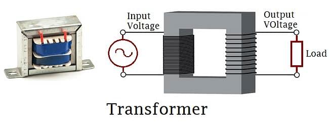
Transformer
The video below explains this:
Transformers Detailed Video Explanation:
Read More:
Transformer Types
[Click Here for Previous Year Questions]
Transformers have a wide variety of applications in the field of electronics. They are used in various sectors such as the power generation grid, distribution sector, transmission, and electric energy consumption. Transformers are classified into various types depending on the following factors:
- Working Voltage Range
- Medium used in Core
- Winding Arrangement
- Installation Location
Based on Voltage Levels
Based on the value of input and output voltage, there are two types of transformers namely Step-up and Step-down transformers.
Step-up Transformers
- They are used to increase the voltage level.
- The output voltage is higher than the input voltage.
- They are mainly used between the power generator and the power grid.
Step-down Transformers
- They are used to decrease voltage levels.
- The output voltage level is lower than the input voltage level.
- They are mainly used in home appliances to step down (decrease) the voltage from the main supply.

Based on the Medium of Core Used
In the transformer, the primary and secondary coils are wound around cores to produce mutual magnetic inductions. Based on the material of the core used, different kinds of transformers are available in the market.
- Air Core Transformers: The primary and secondary coils wound around a non-magnetic strip and air acts as a medium of flux linkage between them.
- Iron Core Transformers: The primary and secondary coils wound around iron plates which are stacked together to form a perfect linkage path for flux.

Air-Core and Iron-Core Transformers
Based on Winding Arrangement
Autotransformers are the only kind of transformer based on winding arrangement. These kinds of transformers contain only one coil wound over a laminated core. In Autotransformers, primary and secondary windings share the same coil.
Based on Install Location
- Power Transformers: They are majorly used in power generation stations as they are suitable for major higher voltages.
- Measurement Transformers: They are used to measure voltage, electric current, power, etc.
- Distribution Transformer: They are used at distribution lanes for domestic purposes and are designed for carrying low voltages.
- Protection Transformers: They are used for component protection from voltage fluctuation.
Working of Transformers
[Click Here for Sample Questions]
Transformers work on the principle of Faraday’s law of electromagnetic induction and mutual inductions.
- The basic structure of a transformer contains two coils wound over a closed core.
- The first coil through which the input AC current flows is called the primary coil.
- The second coil through which AC current is generated is called the secondary coil.
- Both of the coils have mutual inductions.
- When AC current is passed through the primary coil, it generates a varying magnetic flux.
- The varying magnetic flux generates emf (voltage) in the secondary coil as per Faraday’s law.
- This phenomenon is referred to as Mutual Induction.

Parts of a Single-Phase Transformer
[Click Here for Previous Year Questions]
A transformer is generally made up of two parts namely the Core and the Windings. The various parts of the single-phase transformers are as follows:
Core
- The core acts as a supportive medium for the flow of magnetic flux.
- It helps in the low reluctance path for the magnetic flux to pass through.
- It is generally made up of iron or copper plates stacked together to reduce reluctance.
- The material of the core varies depending on various factors such as operating voltage, current, power, etc.
Windings
- Windings are the coils winded over the metal core to produce and re-generate the emf through mutual induction.
- The winding wire is insulated from the outside to avoid a short circuit.
- Various kind of insulating agents is used for the same.
- Generally, copper wire is used for windings due to its high conductivity and ductile properties.
- Two kinds of windings generally used in transformers are Primary and Secondary Windings.
- The magnitude of output voltage depends on the number of turns in the primary and secondary windings.

Insulation Agents
Insulation is crucial for transformers to separate windings from each other and avoid short circuits. It facilitates the process of mutual induction. It has an influence on the durability and stability of a transformer. The things used in the insulators in a transformer are as follows:
- Insulating Oil
- Insulating Tape
- Insulating Paper
- Wood-based Lamination
What is Ideal Transformer?An ideal transformer is a transformer with no losses. There is no magnetic leakage flux, no iron loss in the core, and ohmic resistance in its windings. |
EMF Equation of Transformer
[Click Here for Sample Questions]
EMF equation of a transformer gives the measure of EMF or electromotive force induced in the primary and secondary windings.
- Assume a transformer of N1 turns in the primary winding and N2 turns in the secondary winding.
- Now, when voltage V is applied to the transformer, emf E1 is induced in the primary winding.
- It will induce another emf E2 in the secondary winding by mutual induction.
- The frequency of the induced emf will be equal to the supply frequency f.
- The flux thus formed is a sinusoidal wave that rises to a maximum value Φm and decreases to a negative maximum Φm.
- Hence, the flux reaches a maximum in one-quarter of a cycle., so the time taken is equal to T/4.
| Average Rate of Change of Flux = Φm/(T/4) = 4fΦm |
Here,
- f = Frequency
- T = 1/f
Induced EMF Per Turn = Rate of Flux Change Per Turn
Form Factor = rms Value/Average Value
Rms value = 1.11 (4fΦm) = 4.44 fΦm [The form factor of a sine wave is 1.11.]
RMS Value of EMF Induced in Winding = RMS Value of EMF Per Turn x Number of Turns
- Primary Winding: Rms value of induced emf = E1 = 4.44 fΦm * N1
- Secondary Winding: Rms value of induced emf = E2 = 4.44 fΦm * N2
| \({E_1 \over N_1} = {E_2 \over N_2} = 4.44fΦm\) |
Voltage Transformation Ratio
[Click Here for Previous Year Questions]
Voltage Transformation Ratio is the ratio of EMF to the number of turns in the respective coil. The voltage transformation ratio k can be written as:
| \({E_1 \over N_1} = {E_2 \over N_2} = k\) |
- Step-up Transformers: N2 > N1, K>1
- Step-down Transformers: N2< N1, K<1
- The output voltage (E2), in terms of K, can be written as E2 = E1 x K.
Transformer Efficiency
[Click Here for Sample Questions]
The ability of the transformer to minimize power loss is called its efficiency. The higher the efficiency, the better will be given transformer.
\(Efficiency\left ( \eta \right ) = \frac{Output\, Power}{Input \,Power}\times 100\)
\(Efficiency\left ( \eta \right ) = \frac{P_{out}}{P_{out}+ P_{loses}}\times 100\)
\(Efficiency\left ( \eta \right ) = \frac{V_{2}I_{2}cos\theta }{V_{2}I_{2}cos\theta + P_{c} +P_{cm}}\times 100\)
Where
- Pcu = Psc
- Pc = Poc
\(\eta_{(full load)} = \frac{VAcos\theta }{VAcos\theta + P_{c} + P_{cm}}\times 100\)
\(\eta_{(load n)} = \frac{nVAcos\theta }{nVAcos\theta + P_{c} + n^{2}P_{cm}}\times 100\)
Applications of Transformer
[Click Here for Previous Year Questions]
The applications of transformers are as follows:
- They are used in the transmission of electrical energy through wires over long distances.
- They are used as voltage regulators.
- Transformers with numerous secondary windings are used in radio and TV receivers that need different voltages.
Solved Examples on Transformers
[Click Here for Sample Questions]
Here are a few solved examples to understand the concepts related to transformers better:
| Example 1: Consider a transformer with 600 turns of the primary winding and 20 turns of the secondary winding. What will be the secondary voltage if the secondary circuit is open and the primary voltage is given as 140 V? Solution: Given that
So,
Therefore, the voltage on one turn will be Vt = V2/N2 = V1/N1 k = V2/N2 = V1/N1 Here k is the transformation ratio. V2 = N2/N1 x V1 V2 = 20/600 x 140 V2 = 4.6 V Thus, the secondary voltage will be 4.6 V. Example 2: A transformer has 1600 loops in the primary winding and 1000 loops in the secondary winding. What is the current in the secondary coil if the current in the primary coil is 6 Ampere? Solution: Given that
We know that I2/I1 = N1/N2 I2/4 = 1600/1000 I2 = 6.4 A Thus, the current on the secondary coil is 6.4 Amperes. |
Check More:
Things to Remember
- Transformer is a device used to change the AC voltage without changing the frequency between the circuits.
- Transformers have a wide range of applications in power transmission and distribution applications.
- Core and Windings are the two components that make up a transformer.
- They are classified into different types based on the voltage, the medium of the transformer core, and the winding arrangement.
- Transformers work on the principle of electromagnetic induction and mutual induction.
- EMF equation of a transformer is given as \({E_1 \over N_1} = {E_2 \over N_2} = 4.44fΦm\).
Previous Year Questions
- Transformer is used to…
- A transformer is employed to…
- The current drawn by the primary of a transformer, which steps…
- A step-up transformer works on 220V and gives 2 A to an…
- A transformer having an efficiency of 90% is working on… (NEET 2014)
- Ferromagnetic materials used in a transformer must have… (BCECE 2009)
- In a step-up transformer, the turn ratio is 1:2. A Leclanche cell… (JIPMER 2010)
- For a transformer, the turns ratio is 3 and its efficiency is… (KCET 2013)
- A transformer of 100% efficiency has 200 turns in the primary… (MGIMS Wardha 2010)
- A step-up transformer operates on a 230V line and a load…
Sample Questions
Ques. Which of the following does not change in a transformer?
(A) Current
(B) Voltage
(C) Frequency
(D) All of the Above (1 Mark)
Ans. (C) Frequency
Explanation: Transformers are static devices that convert electrical power from one circuit to another without changing its frequency. The input and out supply frequency always remain the same.
Ques. What are the functions of a Transformer? (3 Marks)
Ans. A transformer performs the following functions:
- It is used to transfer electrical energy from one circuit to another.
- It transfers electrical power through electromagnetic induction.
- It also helps in the electric power transfer without any change in frequency.
Ques. (i) Describe briefly the underlying principle and working of a step-up transformer.
(ii) Write any two sources of energy loss in a transformer.
(iii) A step-up transformer converts a low input voltage into a high output voltage. Does it violate the law of conservation of energy? Explain. (3 Marks)
Ans. (i) A transformer is based on the principle of mutual induction, i.e. whenever the amount of magnetic flux linked with a coil changes, an emf is induced in the neighboring coil.
(ii) Two factors for energy losses in a transformer are:
- Eddy Currents
- Hysteresis loss
(iii) No, it does not violate the law of conservation of energy because a voltage increase is accompanied by a decrease in it. The current in such a way for an ideal transformer input power equals the output power.
Ques. What are the two types of Windings in Transformers? (3 Marks)
Ans. A transformer has mainly two types of windings namely Primary windings and Secondary windings.
- Primary Winding: They are the set of turns of windings to which the supply current is fed.
- Secondary Winding: They are the set of turns of winding from which output is taken.
Both of these windings are insulated from each other using insulation coating agents.
Ques. Mention the various energy losses in a transformer. (2 Marks)
Ans. The various energy losses in a transformer are as follows:
- Eddy Current Loss: Eddy current in the iron core of the transformer facilitates the loss of energy in the form of heat.
- Flux Leakage: Total fluxes linked with the primary do not completely pass through the secondary which denotes the loss in the flux.
Ques. What are the types of transformers based on voltage level? (2 Marks)
Ans. The types of transformers based on voltage level are as follows:
- Step-up Transformer: In this, the secondary output voltage is higher than the input voltage.
- Step-down Transformer: In this, the output voltage is less than the input voltage.
Ques. What is a Transformer? Can it explode? (2 Marks)
Ans. A transformer is defined as an electrical device that is used for stepping up or stepping down AC voltages. It is a voltage-controlling device used widely in the distribution and transmission of alternating current power. It is used to increase or decrease the voltage. Yes, they can burn or explode when lightning strikes, overloading, corrosion, power surges, etc.
Ques. Is Insulation necessary for transformers? (3 Marks)
Ans. Yes, insulation is very essential for transformers in order to separate primary and secondary windings from each other and to avoid short circuits. It also affects the durability and stability of a transformer. Transformers are insulated with the help of the following:
- Insulating Oil
- Insulating Tape
- Insulating Paper
- Wood-based Lamination
Ques. What is the EMF equation of a transformer? (3 Marks)
Ans. The EMF equation of a transformer is as follows:
\({E_1 \over N_1} = {E_2 \over N_2} = k\)
Here,
- E1 is the supply voltage on the primary winding.
- E2 is the terminal voltage on the secondary winding.
- N1 is the number of turns in the primary winding.
- E2 is the number of turns in the secondary winding.
- k is the transformation ratio constant.
Ques. What is the core of a Transformer? (1 Mark)
Ans. The core of a transformer acts as a support to the windings, both primary and secondary windings. It also offers a low reluctance path to the flow of magnetic flux. The composition of the core of a transformer is affected by the factors such as operating voltage, current, power, etc.
For Latest Updates on Upcoming Board Exams, Click Here: https://t.me/class_10_12_board_updates
Check-Out:


Comments