


Education Journalist | Study Abroad Lead
AC Voltage Applied to an Inductor implies an AC circuit that consists only of an inductor of inductance L which is connected to an AC source. The AC voltage across the source is V = Vm sin (∏t). The changing current output of the AC source gives a back emf in the coil of magnitude which is given by VL = L di/dt. Here, we will learn more about the functioning of an electric circuit where we will have an inductor and an AC voltage V which is represented by “~”.
| Table of Content |
Keyterms: Ac Circuit, Ac Voltage, DC Circuit, Inductance, Electric Circuit, Electric Current, Current, Magnitude, Inductor, Energy
Definition
[Click Here for Previous Year Questions]
- In the electric current, an inductor works as the most power electronic circuit that stores energy in the form of magnetic energy. The inductor is also called a choke, reactor, or coil. The inductor either acquires charge or loses its charge on every use, for equalizing the current flowing through it.
- The inductor voltage can measure the amount of voltage generated for a particular rate of change of current.
Also Read:
| Related Articles | ||
|---|---|---|
| Alternating Current Important Questions | Alternating Current Ncert Solutions | RMS value alternating current |
| Time Constant Formula | Reactance and Impedance | Phasor Representation AC |
AC Voltage applied to an inductor
[Click Here for Sample Questions]
An inductor can either oppose or block the way of alternating current. There are two ways to do this: one is to connect the inductor to the DC supply and the next is to connect it to the AC supply.
- In the DC circuit, the bulb glows brightly because there will be a constant flow of current through the inductor.
- In the AC circuit, the bulb doesn’t glow brightly because the inductor opposes or blocks the flow of alternating current.
Now we should use Lenz’s law to explain the opposition to the flow of AC current through an inductor:

Alternating current varies with magnitude as well as direction. When the current increases from zero to top value during the time interval, the current of the coil increases which means the magnetic field connected to the coil also increases.
EMF is given by Lenz’s law as: E = − dΦ/dt
In some cases, when the current decreases from a maximum to a low value during a time interval, the coil’s magnetic field decreases as well and it becomes zero.
So, the induced EMF is given by: E = − Ldt/di
Since, Φ= L×i
The amount of Voltage required by the AC source:
V= L×dt/di
To maintain the current, generated voltage must be equal to the reverse Emf. So the Voltage applied to the coil is given by:
V= L×di/dt
Check out question on Impedence of the circuit…
The relation between Current and Voltage across the Coil
V= L×di/dt
di/dt= V/L
di/dt= Vmsinωt/L…. (1)
Here, Vm = Maximum voltage
After integrating equation (1)
i = ∫ Vmsinωt/ Ld×t
i = - Vmcosωt/ωL
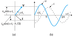
i = Vmsin (ωt- 90)/ ωL
i = imsin (ωt- 90)
Here, im = Maximum value of current
The expression for Inductive Reactance
V= Vmsinωt
i= imsin( ωt - 90)
i = -imcosω
im = Vm/ ωL
im = Vm/XL
Where, XL = Inductive Reactance
Inductive reactance XL = ωL
Inductive XL = 2πfL
The SI unit of Inductive Reactance is Ohm. The inductive reactance is proportional to the angular frequency. When frequency increases the value of the reactance also increases and when frequency decreases the value of the reactance also decreases. If the value of the DC current is f = 0 then XL = 0.
Power in AC Circuit
[Click Here for Previous Year Questions]
Power Consumption
We know that P = VI. So the power consumed in an AC circuit is:
P= ( Vm× sinωt) × ( 1m× sin(ωt+Φ ))
Finding the average value of power
Pavg = (Vm × sinωt) × ( 1m × sin(ωt+Φ ) )
Using trigonometric identity:
2 sin A sin B = cos(A−B)–cos(A+B)
We get:
Pavg= Average of VmIm[2⌊cosΦ–cos(2ωt + Φ )⌋/2
Power Factor
The power factor of an AC electrical circuit can be defined as the ratio of the real power passing to the actual power in the circuit through the circuit.
Power Factor = Apparent Power/True Power

Also Read:
Previous Year Questions
- the resistor R in a series LCR circuit connected to an AC source, it is found that the ratio…..[JEE Main 2014]
- Consider the LR circuit shown in the figure. If the switch S is closed at t=0 then….[JEE Main 2019]
- The current at a time when the potential difference across the capacitor is 5V, is….[ JEE Main 2018]
- An arc lamp requires a direct current of 10A at 80V to…..[JEE Main 2016]
- A sinusoidal voltage of peak value 283V and angular frequency 320/s is applied to...[JEE Main 2017]
- A series AC circuit containing an inductor….[JEE Main 2019]
Sample Questions
Ques: The number of turns of a solenoid are doubled without changing its length and area of cross section. The self inductance of the solenoid will be _________ times. (CBSE 2020)
Ans. Four times. Based on the question, the number of turns in a coil is doubled without any change in the inductance lending to the coil. Therefore, the inductance of the coil becomes four times. Meaning, the self inductance of the solenoid becomes four times.
Ques: Define the quality factor of resonance in a series LCR circuit. What is its S.I unit? (CBSE 2016)
Ans: The quality factor associates the peak or maximum energy that is stored in the circuit, i.e, the reactance to the energy dissipated (the resistance) during each cycle of oscillation.
Quality factor in series LCR circuit is expressed as
Q = woL/ R = 1/R √L/C
Quality factor is dimensionless quality, thus it has no S.I unit.
Ques: What is capacitive reactance? What are its S.I. units? (CBSE 2015)
Ans: When connected to an electrical circuit, the resistance offered by a capacitor is known as capacitive reactance.
Alternatively,

∏ = angular frequency of the source
C = capacitance of the capacitor
The S.I. unit of capacitive reactance is ohm.
Ques: A resistance R and a capacitor C are connected in series to a source V = V0 sin \(\Box\)t. Find,
a) the peak value of the voltage across (i) the resistance and (ii) the capacitor
b) the phase difference between the applied voltage and current. Which one among them is ahead? (CBSE 2020)
Ans:
a) (i) Peak value of the voltage across resistance:
Source voltage V = V0 sin \(\Box\)t
Resistance = R
Capacitor = C
By using the formula of peak voltage across the resistance

b) As we know that, if there is voltage across the resistance, then the voltage will be in phase with the current.
Again, if there is voltage across the capacitance, then the voltage must lag the current by 90o.
Therefore, the voltage across the resistance will be ahead.
Ques: The two bulbs rated (P1, V) and (P2, V) are connected (i) in series and (ii) in parallel across a supply V, find the power dissipated in the two combinations in terms of P1 and P2. (CBSE 2019)
Ans. Electric power of a circuit implies the rate at which the work is done by the source of emf in maintaining the current in the electric circuit. The electric power is given by,
\(P = IV = I^2 R= \frac{V^2}{R}\) (as V = IR)
Here, V = potential difference
I = current
R = resistance
(i) when two bulbs rated (P1, V), (P2, V) are connected in series

The current is the same through each bulb. If the resistances of two bulbs are R1 and R2, then the effective resistance of the circuit is,
R = R1 + R2
Using the relation,

(ii) when two bulbs rated (P1, V), (P2, V) are connected in parallel

Thus the effective power in this case will be, P = P1 + P2
Ques 1: (a) Draw a diagram of a device which can be used to decrease high ac voltage into low ac voltage and state its working principle. Also write four sources of energy loss in this device.
(b) A small town with a demand of 1200 kW of electric power at 220 V is located 20 km away from an electric plant that generates power at 440 V. The resistance of the two wire line carrying power is 0.5 Ω per km. The town gets the power from the line through a 4000- 200 V step-down transformer at a sub-station in the towns. Estimate the line power loss in the form of heat. (CBSE 2019)
Ans: (a) Transformer or a step-down transformer is the device which is used to decrease high ac voltage into a low ac voltage.
A transformer works on the principle of Faraday’s Law of electromagnetic induction. According to the law of electromagnetic induction, when magnetic flux linked with a coil changes, an emf is induced in the coil. Transformer comprises two coils called primary and secondary coils. The ac current in the primary coil changes magnetic flux linked with the secondary coil and therefore an emf is induced in the secondary coil.

Sources of energy loss in transformer are,
- Copper loss: The coil of a transformer that is made of copper has a finite resistance due to which some energy as heat is lost.
- Iron loss: Some energy is lost in a bulk due to induced eddy current in the iron core.
- Magnetic loss: There is some loss of energy due to leakage of flux as all magnetic flux in the primary coil does not pass through the secondary coil.
- Hysteresis loss: Due to alternating magnetization and demagnetization of the iron core, there is some loss of energy as heat.
(b) Electric power required by small town, P = 1200 kW = 1200 x 103 W
Supply voltage, 220 V
Electric power generating at electric plant, 440 V
Resistance of wire carrying power, 0.5 Ω per km
Distance between the electric power generator and the town, 20 km
Total resistance of the wire
R = 0.5 (20+20) = 20 Ω
Town gets power from a step-down transformer rated 4000- 220 V
Hence, the input voltage is 4000 V = Vin
Output voltage is 220 V = Vout
Thus, the rms current in the wire,
\(I_{rms} = \frac{P}{V_{in}} = \frac{1200 * 10^3}{4000} = 300A\)
Power loss as heat is,
\(I_{rms}^2 R = (300)^2 * 20\)
= 9 x 104 x 20 = 180 x 104 = 1800 x 103 W
Thus, the power loss in the form of heat is 1800 kW.
Ques 2: (a) Draw graphs that illustrate the variation of inductive reactance and capacitive reactance with frequency of the applied ac source.
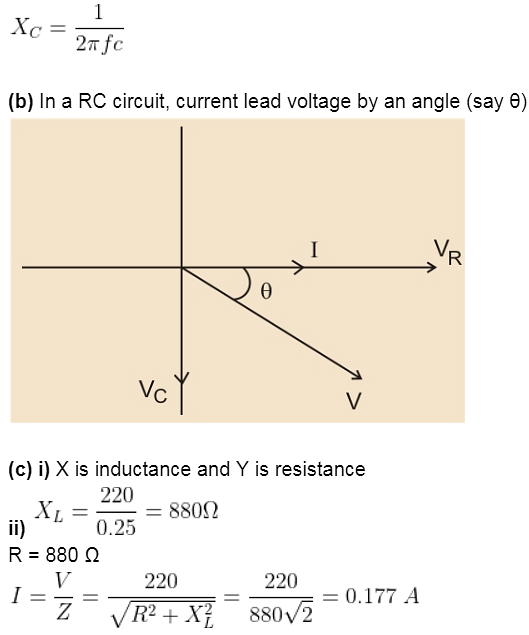
(b) Draw a phasor diagram for a series RC circuit connected to an ac source.
(c) An alternating voltage of 220 V is applied across a device X where a current of 0.25 A flows and lag behind the applied voltage in phase by π/2 radian. If the same voltage is applied across another device Y, the same current flows but not it is in the phase with applied voltage.
(i) name the devices X and Y
(ii) calculate the current that flows in the circuit when the same voltage is applied across the series combination of X and Y. (CBSE 2018)
Ans: (a) Inductive reactance

Capacitive reactance

Where,
Ques 3: (a) Draw a labelled diagram of an ac generator. Give the expression for the emf that is induced in the rotating coil of N turns each of cross-sectional area A in the presence of a magnetic field \(\overrightarrow{B}\) .
(b) A horizontal conducting rod of 10 m long extends from east to west is falling with a speed 5.0 ms-1 at right angles to the horizontal component of the Earth’s magnetic field 0.3 x 10⁻⁴ Wbm-2 . Find out the instantaneous value of the emf induced in the rod. (CBSE 2017)
Ans:

Based on Faraday’s law electromagnetic induction, a machine that converts a given energy into electrical energy is called a generator. There are two types, AC generator and DC generator. The DC generator’s size is comparatively bigger than the AC generators whose loss are generally lower than the DC generators.
Let us assume t = 0 at instant. In the direction of the magnetic field, the plane of the coil is perpendicular to the direction of the magnetic field. Thus, the flux passing through the coil is maximum.
The coil through flux pass at t = 0
The rotation of the coil on an axis in which angular velocity is constant is represented by ∏.
The coil rotated on an angle in time t is ∏t.
Flux created is,

Therefore, E = N∏BA sin ∏t
(b) E = BIV sin90 = BIV
= 0.3 x 10 – 4 x 10 x 5
= 1.5 mV
The instantaneous value of the emf induced in the rod is 1.5 mV.
Ques 4: A group of students, while returning from the school, has noticed a box marked “ Danger H.T. 2200 V” at a substation in the main street. They did not understand the utility of such high voltage and they argued that the supply was only 220 V. next day they asked their teacher the same question. The teacher thought it to be an important question and hence explained it to the whole class.
Answer the following questions:
(i) What device is used to bring high voltage down to low voltage of ac current and state its working principle.
(ii) Is it possible for the device to bring down the high dc voltage to the low voltage? Explain.
(iii) Write the values displayed by the students and the teacher. (CBSE 2015)
Ans. (i) The device that is used to bring the high voltage down to low voltage of ac current is the transformer. A transformer works on the principle of mutual induction of two circuits or windings. When current in one circuit changes, the emf is induced in the neighbouring circuit.
(ii) It is not possible for the transformer to lower the high dc voltage because it works on the principle of mutual induction. The magnetic flux linked with the secondary coil changes when the current linked with primary coil changes. This change in flux induces the emf in the secondary coil. Moreover, the current will remain constant if a direct current is applied to the primary coil. Therefore, there is no mutual induction and thus no emf is induced.
(iii) The value of gaining and widening knowledge and curiosity about learning new things are being shown by the students. Again, the value of sharing good education and undertaking the doubts of the students has been displayed by the teacher.
Ques 5: (i) A series L-C-R circuit is connected to an ac source of variable frequency. Draw a diagram to deduce the expressions of the amplitude of current and phase angle.
(ii) Obtain the condition at resonance. Draw a plot that illustrates the variation of a current with the frequency of AC source for two resistances, R1 and R2 (R1 > R2). Hence define the quality factor Q state its role in turning off the circuit. (Delhi 2014)
Ans. (i)
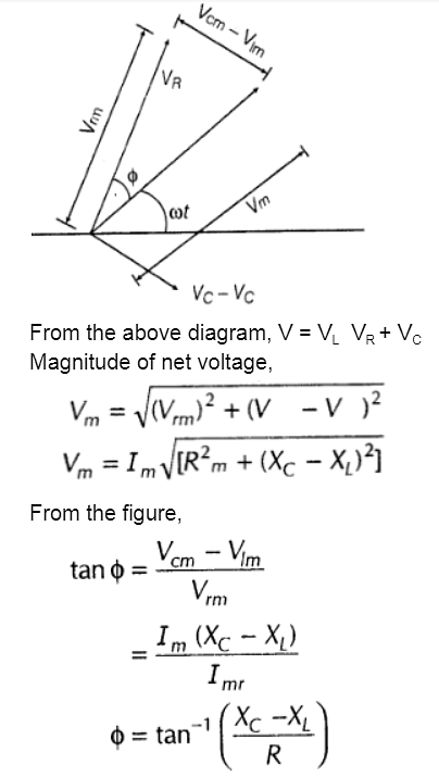
(ii)

Let us assume that XL > XC,
⇒ VL > VC
But, VR = IR, VL = IXL, VC = IXC

For Latest Updates on Upcoming Board Exams, Click Here: https://t.me/class_10_12_board_updates
Check-Out:


Comments