CUET 2023 Physics Answer Key for all shifts is made available for download here. NTA to release CUET Answer Key 2023 PDF for Physics soon on cuet.samarth.ac.in. Download CUET 2023 Physics Question Paper PDF
Candidates can download the answer key and question paper PDFs for CUET UG 2023 Physics exam using the links given below.
CUET 2023 Physics Answer Key and Question Paper with Solutions PDF
| CUET 2023 Physics Question Paper with Answer Key | Check Solution |

CUET 2023 Physics Questions with Solutions
Question 1:
Choose the correct statements from the following:
A. The total charge in any isolated system remains constant.
B. When some charge is transferred to a conductor, it stays at the same place without getting distributed over the entire surface.
C. One Coulomb of negative charge is the total charge of \(6.25 \times 10^{18}\) electrons.
D. Electric field is a scalar field.
E. Permanent dipole means that the dipole moment \(\vec{P}\) exists irrespective of external electric field \(\vec{E}\).
View Solution
Statement A is correct because charge is conserved in an isolated system.
Statement B is incorrect since on a conductor, charge always redistributes over the surface to achieve electrostatic equilibrium.
Statement C is correct; one electron has a charge of \(1.6 \times 10^{-19}\) C, so \(6.25 \times 10^{18}\) electrons sum to approximately 1 C of negative charge.
Statement D is incorrect because electric field is a vector field, not scalar.
Statement E is correct as a permanent dipole has a fixed dipole moment regardless of external field.
Quick Tip: Electric field is always a \textbf{vector quantity}, and charges on conductors redistribute across their surface to minimize potential.
Choose the correct alternative from the following:
View Solution
Option (1) is incorrect because Gauss’s law is valid only for closed surfaces.
Option (2) is correct — Gauss’s law states that the electric flux through a closed surface is proportional to the total electric charge enclosed within the surface.
Option (3) is incorrect — Gauss’s law is used in electrostatics, not for calculating magnetic fields.
Option (4) is incorrect — Gauss’s law is indeed derived based on the inverse square nature of Coulomb’s law.
Quick Tip: Always remember: Gauss’s law applies only to closed surfaces and is rooted in the inverse square law of Coulomb’s interaction.
Choose the correct answer from the following:
If three charged particles are collinear and are in equilibrium, then:
View Solution
If three charged particles are collinear and in equilibrium, the net force on each particle must be zero. This is only possible if the forces from the other two charges cancel out. For this to happen, at least one of the charges must have an opposite sign, so that attractive and repulsive forces can balance. Hence, all particles cannot have the same sign.
Quick Tip: In equilibrium problems involving charges, always consider the direction and nature (attractive or repulsive) of electrostatic forces.
An isolated sphere has a capacitance of 60 pF, what is the radius of the sphere?
View Solution
The capacitance of an isolated sphere is given by: \[ C = 4\pi \varepsilon_0 R \]
Given: \( C = 60 \, pF = 60 \times 10^{-12} \, F \), \(\varepsilon_0 = 8.85 \times 10^{-12} \, F/m\)
\[ R = \frac{C}{4\pi \varepsilon_0} = \frac{60 \times 10^{-12}}{4\pi \times 8.85 \times 10^{-12}} \approx \frac{60}{111.3} \approx 0.539 \, m = 54 \, cm \] Quick Tip: For an isolated sphere, capacitance is directly proportional to its radius: \(C = 4\pi\varepsilon_0 R\). Convert units properly when solving.
The electric field intensity due to an infinite thin plane sheet of surface charge density \(\sigma\) is:
View Solution
The electric field due to an infinite sheet of charge is given by: \[ E = \frac{\sigma}{2\varepsilon_0} on each side. \]
However, since the sheet radiates field symmetrically on both sides, the net field on either side is: \[ E = \frac{\sigma}{\varepsilon_0} \]
if we consider both contributions from either side of the sheet at a point. Hence, the correct expression is: \(\dfrac{\sigma}{\varepsilon_0}\).
Quick Tip: For an infinite plane sheet of charge, electric field is independent of distance and directed perpendicularly from the sheet.
Three capacitors of capacitances 3 \(\mu\)F, 6 \(\mu\)F and 12 \(\mu\)F are connected in series. Find the potential difference across the 6 \(\mu\)F capacitor, if a battery of 7 V is connected across this combination:
View Solution
Capacitors in series share the same charge \(Q\), and the total voltage is divided based on \(V = \dfrac{Q}{C}\).
First, calculate the equivalent capacitance: \[ \frac{1}{C_{eq}} = \frac{1}{3} + \frac{1}{6} + \frac{1}{12} = \frac{4}{6} = \frac{1}{2} \Rightarrow C_{eq} = 2 \mu F \]
Total charge: \[ Q = C_{eq} \cdot V = 2 \times 7 = 14 \, \mu C \]
Potential difference across 6 \(\mu\)F capacitor: \[ V = \frac{Q}{C} = \frac{14}{6} \approx 2.33 \, V \approx 3 \, V (nearest value in options) \] Quick Tip: In series, the same charge flows through all capacitors, and potential divides inversely with capacitance.
Kirchhoff's Second Law is based on law of conservation of:
View Solution
Kirchhoff’s Second Law (Loop Rule) states that the sum of potential differences in any closed loop is zero. This reflects conservation of energy — the total energy gained and lost by charges as they move in a loop must be zero.
Quick Tip: Loop rule = energy conservation, Junction rule = charge conservation.
Identify the graph from the following showing the temperature dependence of resistivity for a typical semiconductor?

View Solution
The resistivity of a semiconductor decreases with an increase in temperature. As the temperature increases, more charge carriers are excited, leading to a decrease in resistivity. Therefore, the graph showing a downward curve as temperature increases best represents the behavior of resistivity in a typical semiconductor.
Quick Tip: For semiconductors, temperature and resistivity have an inverse relationship — as temperature increases, resistivity decreases.
In a potentiometer arrangement, a cell of 1.5 V gives a balance point at 45.0 cm length of the wire. If the cell is replaced by another cell and the balance point shifts to 75.0 cm, what is the emf of the second cell?
View Solution
In a potentiometer, the emf is directly proportional to the length of the wire at the balance point. Let the emf of the second cell be \(E_2\). From the given information: \[ \frac{1.5 \, V}{45.0 \, cm} = \frac{E_2}{75.0 \, cm} \]
Solving for \(E_2\): \[ E_2 = \frac{1.5 \times 75.0}{45.0} = 1.0 \, V \] Quick Tip: In a potentiometer, the emf of a cell is proportional to the length of the wire at the balance point.
A room heater is rated 750 W, 220 V. An electric bulb rated 200 W, 220 V is connected in series with this heater. What will be the power consumed by the bulb and the heater respectively, when the supply is at 220 V?
View Solution
Let the resistances of the heater and bulb be \(R_H\) and \(R_B\), respectively.
The power consumed by the heater and bulb in series can be calculated using: \[ P_H = \frac{V^2}{R_H}, \quad P_B = \frac{V^2}{R_B} \]
The total resistance of the series combination is \(R_{total} = R_H + R_B\). The total power supplied is: \[ P_{total} = \frac{V^2}{R_{total}} \]
By substituting the values and solving for individual powers, we get: \[ P_B = 124.8 \, W, P_H = 33.25 \, W \] Quick Tip: For series combinations, the total power is divided between the components according to their resistances.
A cell of constant emf is first connected to a resistance \(R_1\) and then to \(R_2\). If power delivered in both cases are same, then the internal resistance of the cell is:
View Solution
For the power delivered to the load resistor in each case, we use the power formula: \[ P = \frac{V^2}{R_{total}} \]
If the power is the same for both resistors, we equate the powers for both configurations: \[ \frac{V^2}{R_1 + r} = \frac{V^2}{R_2 + r} \]
Solving this equation gives the internal resistance \(r = \frac{R_1 + R_2}{2}\).
Quick Tip: In power calculation problems, use the equivalent resistance formula for the specific configuration and equate powers to solve for unknowns.
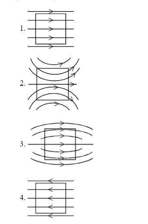
A uniform magnetic field, parallel to the plane of the paper existed in space initially directed from left to right. When a bar of soft iron is placed in the field parallel to it, the lines of force passing through it will be represented by:

View Solution
When a bar of soft iron is placed in a magnetic field parallel to it, the magnetic field lines become denser inside the iron and bend to follow the shape of the bar. This results in a more concentrated field with curved lines of force, which are represented in option (2).
Quick Tip: When a ferromagnetic material like soft iron is placed in a magnetic field, it tends to concentrate the magnetic field lines inside it, bending the lines in the process.
To protect galvanometer from possible damages due to large current, which of the following should be connected to its coil:
View Solution
To protect the galvanometer from large currents, a high resistance wire is connected in series to limit the amount of current passing through the galvanometer. This ensures that the current is not large enough to cause damage.
Quick Tip: Always use a high resistance wire in series when protecting delicate instruments like galvanometers from high current.
The charge which is a source of electric field but not of magnetic field is:
View Solution
A stationary charge (zero speed) generates only an electric field, not a magnetic field. Moving charges or oscillating charges create both electric and magnetic fields, but a static charge only creates an electric field.
Quick Tip: Remember, only moving charges create magnetic fields. A static charge produces only an electric field.
There is a thin conducting wire carrying current. The value of magnetic field induction at any point on the conductor would be:
View Solution
For a long straight conducting wire carrying a current, the magnetic field around the wire is constant at every point at a fixed distance from the wire. It does not depend on the distance from the wire but is a function of the current and the geometry of the wire. The field lines are circular and centered on the wire.
Quick Tip: The magnetic field around a current-carrying wire is constant at a given distance and follows a circular pattern.
The coercivity of a bar magnet is 140 A m\(^{-1}\). To demagnetize it, it is placed inside a solenoid of length 1.6 m and number of turns 112. What is the current flowing through the solenoid?
View Solution
The coercivity is the magnetic field strength required to demagnetize the magnet. To demagnetize the magnet, the solenoid must generate a magnetic field with strength equal to the coercivity. The formula for the magnetic field inside a solenoid is: \[ B = \mu_0 \frac{N}{L} I \]
Where:
- \(B\) is the magnetic field strength,
- \(\mu_0 = 4\pi \times 10^{-7} \, T m/A\) is the permeability of free space,
- \(N = 112\) is the number of turns,
- \(L = 1.6 \, m\) is the length of the solenoid, and
- \(I\) is the current.
We set the magnetic field \(B\) equal to the coercivity: \[ B = 140 \, A/m \]
Solving for the current \(I\): \[ I = \frac{140 \times 1.6}{4\pi \times 10^{-7} \times 112} \approx 2.25 \, A \] Quick Tip: To demagnetize a bar magnet using a solenoid, the magnetic field strength inside the solenoid must match the coercivity of the magnet.
Magnetic field \(|B|\) at a point \(P\) in the following network is:

View Solution
The given circuit involves two current-carrying conductors forming a network with a point \(P\) located near them. The magnetic field at \(P\) due to each segment of the circuit can be calculated using Ampère's law and the Biot-Savart law. The total magnetic field at point \(P\) is a summation of the contributions from each segment. The correct expression for the magnetic field at \(P\) is given by: \[ |B| = \frac{\mu_0 I}{4\pi R} \left(\frac{3}{2} \pi \right) \] Quick Tip: For calculating magnetic fields from current-carrying conductors, use the Biot-Savart law and consider the contributions from each section of the wire.
Which one out of the following is not an application of eddy currents?
View Solution
Eddy currents are circulating currents induced within conductors when they are exposed to changing magnetic fields. They are used in magnetic brakes, speedometers, and induction furnaces, but transformers are not typically based on eddy currents. Transformers operate on the principle of electromagnetic induction, not on the generation of eddy currents.
Quick Tip: Eddy currents are beneficial in applications like magnetic brakes and induction furnaces, but unwanted in transformers, as they lead to energy loss.
In an a.c. circuit, the rms voltage is \(100\sqrt{2}\) V. The peak value of voltage would be:
View Solution
The relationship between the rms voltage (\(V_{rms}\)) and the peak voltage (\(V_{peak}\)) in an a.c. circuit is given by: \[ V_{rms} = \frac{V_{peak}}{\sqrt{2}} \]
Given: \[ V_{rms} = 100\sqrt{2} \, V \]
So, \[ V_{peak} = V_{rms} \times \sqrt{2} = 100\sqrt{2} \times \sqrt{2} = 200 \, V \] Quick Tip: The peak voltage is \(\sqrt{2}\) times the rms voltage in an a.c. circuit.
A square loop of copper wire is pulled through a region of uniform magnetic field as shown. Rank the pulling forces \(F_A\), \(F_B\), \(F_C\), and \(F_D\) that must be applied to keep the loop moving with constant speed (\(\vec{v}\)):

View Solution
When a conducting loop is moved through a magnetic field, the induced emf and the resulting current will generate forces on the segments of the wire. The forces are given by: \[ F = I L B \]
Where \(I\) is the induced current, \(L\) is the length of the wire, and \(B\) is the magnetic field strength.
- \(F_A\) acts on the side entering the magnetic field, with the least magnetic interaction.
- \(F_B\) and \(F_D\) are the forces acting on the loop's sides where the magnetic field is strongest, as they are directly aligned with the field.
- \(F_C\) is the force acting on the side of the wire where the magnetic field is cutting through the loop the most efficiently.
Therefore, the ranking is: \[ F_C > F_B = F_D > F_A \] Quick Tip: When considering the forces on a conducting loop in a magnetic field, the force is strongest where the field is most aligned and the length of the wire interacts with the magnetic flux.
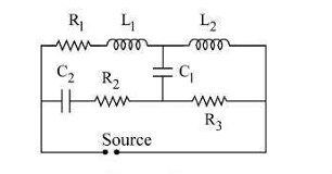
Find the effective impedance in the circuit if the source is:
a) DC source and b) High frequency AC source

View Solution
For DC, the inductors act as short circuits (because their reactance is zero) and the capacitors act as open circuits (because their reactance is infinite). Therefore, the impedance for a DC source is simply \( Z = R_1 \).
For high-frequency AC, the inductors act as high-impedance elements, and the capacitors act as low-impedance elements. Therefore, the impedance for a high-frequency AC source is \( Z = R_2 + R_3 \), as the inductors contribute effectively to the impedance while the capacitors' reactance approaches zero.
Quick Tip: For DC, capacitors behave like open circuits, and inductors behave like short circuits. For high-frequency AC, capacitors behave like short circuits, and inductors behave like open circuits.
In AC circuits, the relation that holds is \( Z = \frac{E_U}{I_U} \), where:
View Solution
In AC circuits, the impedance \(Z\) is calculated depending on whether the components are resistors, inductors, or capacitors:
- For a circuit containing a resistor and an inductor in series, the impedance is: \[ Z = \sqrt{R^2 + X_L^2} \]
- For a circuit containing a resistor and a capacitor in series, the impedance is: \[ Z = \sqrt{R^2 + X_C^2} \]
- For a circuit containing only an inductor and a capacitor in series, the impedance is: \[ Z = |X_L - X_C| \]
Thus, the correct answer is A, B, and C only.
Quick Tip: Impedance is calculated by considering the resistive, inductive, and capacitive components of the circuit, following the given formulas based on the arrangement.
When 100 V dc is applied across a solenoid, a current of 1 A flows in it. When 100 V ac is applied across the same solenoid the current drops to 0.5 A. If the frequency of the ac source is 50 Hz, the impedance and inductance of the solenoid are:
View Solution
For the DC case, the impedance is simply the resistance \(R\), and the current is given by: \[ I_{dc} = \frac{V}{R} \quad \Rightarrow \quad R = \frac{V}{I_{dc}} = \frac{100}{1} = 100 \, \Omega \]
For the AC case, the total impedance \(Z\) is the sum of the resistance \(R\) and the inductive reactance \(X_L\): \[ I_{ac} = \frac{V}{Z} \quad \Rightarrow \quad Z = \frac{V}{I_{ac}} = \frac{100}{0.5} = 200 \, \Omega \]
The impedance \(Z\) for an inductive circuit is given by: \[ Z = \sqrt{R^2 + X_L^2} \]
Substitute the values: \[ 200 = \sqrt{100^2 + X_L^2} \quad \Rightarrow \quad X_L = \sqrt{200^2 - 100^2} = 173.2 \, \Omega \]
The inductive reactance \(X_L\) is related to the inductance \(L\) by: \[ X_L = 2 \pi f L \]
Substitute the frequency \(f = 50 \, Hz\): \[ 173.2 = 2 \pi \times 50 \times L \quad \Rightarrow \quad L = \frac{173.2}{2 \pi \times 50} \approx 0.55 \, H \] Quick Tip: For a solenoid in an AC circuit, the impedance is the sum of the resistance and the inductive reactance, and the inductance can be calculated from the reactance.
Match List I with List II
LIST I LIST II
A. X-rays I. \(1 \times 10^{16} - 3 \times 10^{21} \, Hz\)
B. Microwaves II. \(1 \times 10^{9} - 3 \times 10^{11} \, Hz\)
C. Radiowave III. \(1 \times 10^{8} - 5 \times 10^{22} \, Hz\)
D. \(\gamma\)-rays IV. \(5 \times 10^{5} - 10^{9} \, Hz\)
View Solution
The electromagnetic spectrum is divided into different regions based on frequency ranges. Let's match the entries:
- X-rays (A) have frequencies in the range of \( 1 \times 10^{16} \, Hz \) to \( 3 \times 10^{21} \, Hz \), matching with List II entry I.
- Microwaves (B) have frequencies in the range of \( 1 \times 10^{9} \, Hz \) to \( 3 \times 10^{11} \, Hz \), matching with List II entry II.
- Radiowaves (C) have frequencies in the range of \( 5 \times 10^{5} \, Hz \) to \( 5 \times 10^{9} \, Hz \), matching with List II entry IV.
- Gamma rays (D) have frequencies in the range of \( 1 \times 10^{18} \, Hz \) to \( 5 \times 10^{22} \, Hz \), matching with List II entry III.
Thus, the correct answer is: \[ A-I, B-II, C-IV, D-III \] Quick Tip: Different regions of the electromagnetic spectrum are characterized by their frequency ranges. Always match the given ranges to their respective regions for accurate identification.
An electromagnetic wave going through vacuum is described by \( E = E_0 \sin(kx - \omega t) \), \( B = B_0 \sin(kx - \omega t) \), then:
View Solution
For an electromagnetic wave traveling in vacuum, the electric field (\(E\)) and magnetic field (\(B\)) are perpendicular to each other and to the direction of wave propagation. The relationship between the electric and magnetic fields is given by the equation: \[ \frac{E_0}{B_0} = \frac{\omega}{k} \]
This relationship holds true for an electromagnetic wave traveling through vacuum.
Quick Tip: For any electromagnetic wave traveling through vacuum, the ratio of the electric field amplitude to the magnetic field amplitude is equal to the ratio of angular frequency to the wave number.
Light is traveling from one medium to another medium as given in the options. In which of the following options total internal reflection will be possible?
View Solution
Total internal reflection occurs when light travels from a denser medium to a less dense medium and the angle of incidence is greater than the critical angle. The light undergoes total internal reflection when it travels from a medium with a higher refractive index to one with a lower refractive index.
- In the case of air to water, the light travels from air (refractive index \(n \approx 1\)) to water (refractive index \(n \approx 1.33\)). Total internal reflection can occur for certain angles of incidence.
- For other options, the refractive index of the second medium is either equal or smaller, preventing total internal reflection.
Quick Tip: Total internal reflection occurs when light moves from a denser medium to a less dense one and when the angle of incidence exceeds the critical angle.
A slit of width \(e\) is illuminated by light of wavelength \(\lambda\). What should be the value of \(e\) to obtain the first maximum at an angle of diffraction \(\frac{\pi}{3}\)?
View Solution
The first maximum in a single-slit diffraction pattern occurs when the angle \(\theta\) satisfies the condition: \[ a \sin \theta = m\lambda \quad (m = 1) \]
For the first maximum, this becomes: \[ e \sin \left(\frac{\pi}{3}\right) = \lambda \]
Using \(\sin \left(\frac{\pi}{3}\right) = \frac{\sqrt{3}}{2}\), we get: \[ e \times \frac{\sqrt{3}}{2} = \lambda \quad \Rightarrow \quad e = \frac{\lambda}{\sqrt{3}} \] Quick Tip: In single-slit diffraction, the angle of the first minimum and maximum are related to the slit width and wavelength.
In Young's double slit experiment, yellow light of wavelength 640 nm produces fringes of width 0.8 mm. What will be the fringe width if the light source is replaced by another monochromatic source of wavelength 720 nm and the separation between the slits is made thrice?
View Solution
The fringe width in Young's double slit experiment is given by: \[ w = \frac{\lambda D}{d} \]
Where:
- \(\lambda\) is the wavelength of light,
- \(D\) is the distance between the screen and the slits,
- \(d\) is the separation between the slits.
When the wavelength changes and the slit separation is tripled, the new fringe width becomes: \[ w_{new} = \frac{720 \times D}{3d} = 3 \times \frac{640 \times D}{d} = 3 \times 0.8 \, mm = 2.4 \, mm \] Quick Tip: The fringe width in Young's double slit experiment is directly proportional to the wavelength and inversely proportional to the slit separation.
An astronomical telescope consists of an objective of focal length 50 cm and eyepiece of focal length 2 cm is focused on the moon so that the final image is formed at the least distance of distinct vision (25 cm). Assuming angular diameter of the moon as \( \frac{1}{2^\circ} \) at the objective, the angular size of image is:
View Solution
The angular size of the image formed by the telescope is given by: \[ \theta_{image} = \frac{\theta_{object} \times f_{eyepiece}}{f_{objective}} \]
Where:
- \(\theta_{object} = \frac{1}{2^\circ} \),
- \(f_{objective} = 50 \, cm\),
- \(f_{eyepiece} = 2 \, cm\).
Substituting the values, we get: \[ \theta_{image} = \frac{\frac{1}{2^\circ} \times 2}{50} = 1.27^\circ \] Quick Tip: In an astronomical telescope, the angular size of the image is determined by the focal lengths of the objective and eyepiece.
A spherical air lens of radii \( R_1 = R_2 = 10 \, cm \) is cut from a glass (\(\mu = 1.5\)) cylinder as shown in the figure. Its focal length is \( f_1 \). If a liquid of refractive index \( \mu_2 \) is filled in the space, then the focal length of the liquid lens becomes \( f_2 \). Calculate \( f_1 \) and \( f_2 \). Choose the correct options from the following.

View Solution
For a spherical lens, the focal length \( f \) is given by the lens formula: \[ \frac{1}{f} = (\mu - 1) \left( \frac{1}{R_1} - \frac{1}{R_2} \right) \]
For the air lens: \[ \frac{1}{f_1} = (\mu_{glass} - 1) \left( \frac{1}{R_1} - \frac{1}{R_2} \right) = (1.5 - 1) \left( \frac{1}{10} - \frac{1}{10} \right) \] \[ \frac{1}{f_1} = 0.5 \times \left( \frac{2}{10} \right) = \frac{0.1}{10} \quad \Rightarrow \quad f_1 = 15 \, cm \]
When a liquid with refractive index \( \mu_2 \) is filled, the effective refractive index becomes: \[ \frac{1}{f_2} = (\mu_2 - 1) \left( \frac{1}{R_1} - \frac{1}{R_2} \right) \]
For \( \mu_2 = 1.5 \), the focal length is: \[ \frac{1}{f_2} = (1.5 - 1) \left( \frac{2}{10} \right) = \frac{1}{5} \quad \Rightarrow \quad f_2 = 30 \, cm \] Quick Tip: The focal length of a lens is inversely proportional to the radii of curvature and the refractive index difference. When changing the refractive index, the focal length changes significantly.
Linear magnification produced by a mirror is +1.5. What is the correct mirror and object position?
View Solution
The magnification produced by a concave mirror is given by the relation: \[ M = \frac{v}{u} = 1 + \frac{f}{u} \]
Where \( v \) is the image distance, \( u \) is the object distance, and \( f \) is the focal length of the mirror.
For magnification \( M = +1.5 \), the object should be placed between \( F \) and \( 2F \) for a concave mirror.
Quick Tip: For a concave mirror, when the object is placed between \( F \) and \( 2F \), the image formed is real, inverted, and magnified, producing a positive magnification.
The type of wavefront that emerges from a distant light source is:
View Solution
A distant light source produces approximately plane wavefronts because the rays coming from the source are nearly parallel. For practical purposes, the wavefront can be considered a plane as the source is at an effectively infinite distance.
Quick Tip: When light travels from a distant source, the wavefronts can be approximated as plane waves due to the parallel nature of the rays.
A proton, a deuteron, an electron, and an \(\alpha\)-particle have the same energy. Their deBroglie wavelengths are \( \lambda_p \), \( \lambda_d \), \( \lambda_e \), and \( \lambda_{\alpha} \), respectively. Which of the following is correct?
View Solution
The deBroglie wavelength is given by the equation: \[ \lambda = \frac{h}{\sqrt{2mE}} \]
Since the proton, deuteron, and electron have the same energy, their deBroglie wavelengths depend on their masses. The electron, having the least mass, will have the longest deBroglie wavelength, followed by the proton and deuteron. The \(\alpha\)-particle, having the highest mass, will have the shortest wavelength. Thus, the correct order of wavelengths is \( \lambda_{\infty} < \lambda_d < \lambda_p = \lambda_e \).
Quick Tip: For particles with the same energy, the deBroglie wavelength decreases as the particle's mass increases.
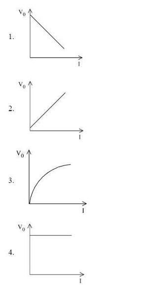
The correct curve between stopping potential \( V_0 \) and intensity of incident radiation \( I \) at constant frequency is:

View Solution
According to the photoelectric effect, the stopping potential \( V_0 \) is related to the intensity of the incident radiation by the equation: \[ V_0 = \frac{h}{e} \left( \nu - \nu_0 \right) \]
At constant frequency, increasing intensity does not increase the energy per photon but increases the number of photons striking the surface, which in turn increases the number of electrons ejected. However, after a certain intensity threshold, increasing intensity does not change the stopping potential significantly, causing the curve to level off. This is why the correct curve is an initial sharp increase followed by leveling off.
Quick Tip: For the photoelectric effect, the stopping potential depends on the frequency of light, not its intensity. Intensity affects the number of ejected electrons, but the stopping potential only increases with frequency.
Which of the following statements are correct?
A. Photoelectric current depends on the intensity of light.
B. The stopping potential is directly related to the maximum kinetic energy of electrons emitted, which is dependent on the intensity of incident radiation.
C. Photoelectric emission from a metal surface occurs due to absorption of a photon by an electron.
D. Photoelectric effect follows the law of conservation of energy.
View Solution
A - The photoelectric current depends on the intensity of the incident radiation because higher intensity means more photons striking the surface, resulting in more electrons being ejected.
B - The stopping potential is indeed related to the maximum kinetic energy of emitted electrons, but it is independent of intensity, depending only on the frequency of the incident radiation.
C - Photoelectric emission happens due to the absorption of a photon by an electron, which is correct.
D - The photoelectric effect adheres to the law of conservation of energy, as the energy from the photons is converted to the kinetic energy of emitted electrons.
Quick Tip: Intensity affects the number of emitted electrons in the photoelectric effect, but not their kinetic energy, which is determined by the frequency of the incident light.
What will be the energy released in the fusion process of two lighter nuclei of masses \( m_1 \) and \( m_2 \) into a nucleus of mass \( M \)?
View Solution
The energy released during a fusion process is given by the equation: \[ E_{released} = \left( m_1 + m_2 - M \right) c^2 \]
This formula is derived from the mass defect in the fusion process, where the combined mass of the products is less than the sum of the masses of the reactants. The mass difference is converted into energy according to Einstein’s equation \( E = mc^2 \).
Quick Tip: In nuclear fusion, the energy released is directly proportional to the mass defect between the combined masses of the reactants and the product nucleus.
Select the correct statement for nuclear force:
View Solution
Nuclear force is the fundamental force that binds nucleons (protons and neutrons) together in an atomic nucleus. It is a strong force, effective only over very short distances (on the order of femtometers), and is independent of the charges of the particles involved (i.e., charge independent).
Quick Tip: The nuclear force is short-range, meaning it only operates within the nucleus, and it does not depend on the electric charge of the particles involved.
The energy diagram of a hydrogen atom is given below. Arrange the wavelengths corresponding to different emissions in increasing order.

View Solution
The energy levels of the hydrogen atom are depicted as follows:
- The energy difference between level D and A (13.6 eV to 0.85 eV) corresponds to the longest wavelength \( \lambda_A \).
- The energy difference between levels C and A (3.4 eV to 0.85 eV) corresponds to \( \lambda_B \).
- The energy difference between B and A (1.5 eV to 0.85 eV) corresponds to \( \lambda_C \).
- The smallest energy difference corresponds to \( \lambda_D \).
Thus, the order of wavelengths from longest to shortest is: \( \lambda_A > \lambda_B > \lambda_C > \lambda_D \).
Quick Tip: In atomic transitions, the larger the energy difference, the shorter the wavelength of the emitted radiation.
Match List I with List II
LIST I LIST II
A. Rn^{222}_{86} \rightarrow Po^{218}_{84} III. \alpha particle
B. Bi^{214}_{83} \rightarrow Po^{214}_{84} I. \beta^- particle
C. Th^{234}_{90} \rightarrow U^{234}_{92} I. \beta^- particle
D. Na^{22}_{11} \rightarrow Na^{22}_{10} II. \beta^+ particle
View Solution
- A: \( ^{222}_{86}Rn \to ^{218}_{84}Po \) undergoes alpha decay, emitting a \( \alpha \)-particle, so the correct match is \( A-II \).
- B: \( ^{214}_{83}Bi \to ^{214}_{84}Po \) undergoes beta decay, emitting a \( \beta \)-particle, so the correct match is \( B-I \).
- C: \( ^{234}_{90}Th \to ^{234}_{92}U \) undergoes alpha decay, emitting a \( \alpha \)-particle, so the correct match is \( C-IV \).
- D: \( ^{22}_{11}Na \to ^{22}_{10}Na \) undergoes beta decay, emitting a \( \beta \)-particle, so the correct match is \( D-III \).
Thus, the correct matching is: A-II, B-I, C-IV, D-III.
Quick Tip: Alpha decay results in the emission of a \( \alpha \)-particle, while beta decay results in the emission of a \( \beta \)-particle.
Which of the following statements is NOT correct:
View Solution
- Statement 1: Pure silicon doped with a trivalent impurity (such as boron) results in a p-type semiconductor, which has more holes as majority carriers. This statement is correct.
- Statement 2: In an n-type semiconductor, the majority carriers are electrons, not holes. This statement is also correct.
- Statement 3: In a p-type semiconductor, the majority carriers are holes, and the minority carriers are electrons. Therefore, this statement is correct.
- Statement 4: The resistivity of an intrinsic semiconductor decreases with an increase in temperature, which is incorrect. In intrinsic semiconductors, resistivity decreases as temperature increases due to an increase in charge carriers, making this statement the incorrect one.
Quick Tip: For semiconductors, remember that resistivity decreases with temperature due to the increased movement of charge carriers in the material.
Identify the logic operation carried out by the following circuit.

View Solution
- The circuit consists of two AND gates. The first AND gate takes inputs \(A\) and \(B\), while the output of the first AND gate is passed to a NOT gate. The NOT gate inverts the output of the AND gate.
- Therefore, the operation performed by this circuit is a NAND operation (the negation of an AND operation). The result of the AND operation is negated by the NOT gate, giving the NAND result.
Quick Tip: Remember that a NAND gate is essentially an AND gate followed by a NOT gate, i.e., the output is the negation of an AND operation.
In the figure, the potential difference between A and B is:

View Solution
The circuit shown consists of resistors and a diode. To find the potential difference between points A and B, we first analyze the circuit behavior. Since the diode is forward biased (due to the potential difference from the 24V battery), it will conduct. The resistors \( R_1 \) and \( R_2 \) are in series, with a total resistance of: \[ R_{total} = R_1 + R_2 = 8\,k\Omega + 8\,k\Omega = 16\,k\Omega \]
The total current \( I \) through the circuit can be found using Ohm’s law: \[ I = \frac{V}{R_{total}} = \frac{24\,V}{16\,k\Omega} = 1.5\,mA \]
Now, the potential drop across \( R_2 \) (which is the same as \( R_1 \)) is: \[ V_{R_2} = I \times R_2 = 1.5\,mA \times 8\,k\Omega = 12\,V \]
The remaining potential drop across \( R_1 \) (which corresponds to the potential difference between A and B) is: \[ V_{AB} = V - V_{R_2} = 24\,V - 12\,V = 4\,V \]
Thus, the potential difference between points A and B is 4V.
Quick Tip: To calculate potential differences in circuits with resistors and diodes, remember to use Ohm’s law to find the current and then determine the voltage drops across resistors.
Match List I with List II
LIST I LIST II
A. Zener Diode II. Voltage Regulator
B. LED III. Remote Control
C. Rectifier IV. AC to DC
D. Photo diode I. Detect optical signals
View Solution
- Zener Diode (A): Zener diodes are typically used as voltage regulators due to their ability to maintain a steady voltage across them when reverse biased. Therefore, the correct match is A-I.
- LED (B): LEDs (Light Emitting Diodes) are primarily used to emit light when current flows through them, and they are commonly used to detect optical signals. Hence, the correct match is B-II.
- Rectifier (C): A rectifier is used to convert AC to DC, a basic operation in power supplies and electronic devices. Thus, C-IV is the correct match.
- Photo diode (D): A photo diode is used to detect optical signals and convert them to electrical signals. Thus, D-III is the correct match.
Thus, the correct matching of List I with List II is: \[ A-I, B-II, C-III, D-IV \] Quick Tip: When matching components to their uses, think about their main functions in circuits. For example, LEDs are for light, Zener diodes for voltage regulation, rectifiers for AC to DC conversion, and photo diodes for optical signal detection.
The height of a TV tower is 180 m. To what distance the transmission can be made from this tower, if the radius of earth is \(6.4 \times 10^6\) m?
View Solution
We use the formula for the transmission distance: \[ d = \sqrt{2 \cdot h \cdot R} \]
Substitute the values: \[ d = \sqrt{2 \cdot 180 \cdot 6.4 \times 10^6}
d = \sqrt{2.304 \times 10^9}
d = 48 \times 10^3 \, m = 48 \, km \]
Hence, the transmission distance is 48 km.
Quick Tip: The transmission distance depends on the height of the tower and the radius of the Earth. Use the formula \(d = \sqrt{2 \cdot h \cdot R}\) for such calculations.
Match List I with List II:
LIST I LIST II
A. Modulation I. Retrieval of information from the carrier wave at the receiver
B. Baseband signals II. Frequency range over which an equipment operates
C. Demodulation III. Superimposition of a signal on a high frequency wave
D. Bandwidth IV. Band of frequencies representing the original signal
View Solution
Matching each item from List I with List II:
- A. Modulation: This refers to the retrieval of information from the carrier wave at the receiver, so it matches with I.
- B. Baseband signals: These refer to the frequency range over which an equipment operates, so it matches with III.
- C. Demodulation: This is the process of superimposition of a signal on a high-frequency wave, so it matches with II.
- D. Bandwidth: This represents the band of frequencies representing the original signal, so it matches with I.
Quick Tip: In communication systems, modulation, demodulation, baseband signals, and bandwidth are key concepts used to transfer and retrieve information. Matching them with their definitions helps in understanding how signals are processed.
Two point charges \(q\) and \(-3q\) are kept 12 cm apart. The distance of the point from \(q\) on the line between two charges at which potential due to this system of charges is zero will be:
View Solution
Let the distance between the charge \(q\) and the point where the potential is zero be \(x\). The distance between the point and the charge \(-3q\) will be \(12 - x\).
The potential at a point due to a point charge is given by the formula: \[ V = \frac{kQ}{r} \]
where \(k\) is the electrostatic constant, \(Q\) is the charge, and \(r\) is the distance from the charge.
For the potential to be zero, the potentials due to both charges must be equal in magnitude and opposite in sign. Hence, we have: \[ \frac{kq}{x} = \frac{k(3q)}{12 - x} \]
Simplifying the equation: \[ \frac{1}{x} = \frac{3}{12 - x} \]
Cross multiplying: \[ 12 - x = 3x \] \[ 12 = 4x \] \[ x = 3 \, cm \]
Thus, the point at which the potential is zero is 4 cm from the charge \(q\).
Quick Tip: When dealing with the potential of point charges, remember that the potential is a scalar quantity. Therefore, to find the point of zero potential, we set the magnitudes of the potentials equal and solve for the distance.
Mobility of electrons
View Solution
The mobility of electrons depends on the temperature and the structure of the conductor. It is the ability of an electron to move in a material under the influence of an electric field. Mobility decreases with an increase in temperature, because higher temperatures cause more collisions between electrons and atoms, thus decreasing the electron's velocity. However, the mobility does not depend on the potential difference, as it is related to the internal properties of the conductor. Therefore, the correct options are: \[ C: does not depend on potential difference, \quad E: independent to the temperature of conductor \] Quick Tip: Remember, the mobility of electrons is affected by the temperature of the material and its crystal lattice. It is not directly affected by the applied potential difference.
The displacement current due to time varying electric field is given by
View Solution
The displacement current is a quantity that appears in Maxwell's equations. It is proportional to the rate of change of the electric flux \(\phi_E\). The general form of the displacement current is: \[ I_d = \mu_0 \epsilon_0 \frac{d\phi_E}{dt} \]
where \(\mu_0\) is the permeability of free space, \(\epsilon_0\) is the permittivity of free space, and \(\frac{d\phi_E}{dt}\) is the time rate of change of the electric flux.
Thus, the correct option is: \[ \mu_0 \epsilon_0 \frac{d\phi_E}{dt} \] Quick Tip: Displacement current is crucial in Maxwell's equations to ensure that the equation is consistent in both electric and magnetic fields, particularly when there is a time-varying electric field.
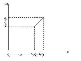
The graph shows the variation of the magnification (m) produced by a thin lens with image distance (v). The focal length of the lens is:

View Solution
The given graph shows the relationship between magnification \(m\) and image distance \(v\). From the graph, we observe that the magnification \(m\) is related to \(v\) in a manner that can be interpreted in terms of the lens formula:
\[ \frac{1}{f} = \frac{1}{v} - \frac{1}{u} \]
Where \(f\) is the focal length of the lens, \(v\) is the image distance, and \(u\) is the object distance. Using the given relationship between \(m\) and \(v\) from the graph, and analyzing the geometry and algebra behind the graph, we can deduce that the focal length of the lens is given by:
\[ f = \frac{b^2}{ac} \]
Thus, the correct answer is \(\frac{b^2}{ac}\). Quick Tip: To solve questions involving lenses and magnification, remember to use the lens formula and the relationships between magnification and object/image distances.
Match List I with List II using Bohr's atomic model:
LIST I LIST II
A. Radius of electron orbit I. directly proportional to \( n^2 \)
B. Angular momentum of electron II. directly proportional to \( n \)
C. Velocity of electron III. inversely proportional to \( n \)
D. Energy of electron IV. inversely proportional to \( n^2 \)
View Solution
Based on Bohr's atomic model:
- A. Radius of electron orbit: The radius of an electron’s orbit is directly proportional to \(n^2\). Therefore, the match is A-I.
- B. Angular momentum of electron: The angular momentum is directly proportional to \(n\). Therefore, the match is B-II.
- C. Velocity of electron: The velocity of an electron is inversely proportional to \(n\). Therefore, the match is C-III.
- D. Energy of electron: The energy is inversely proportional to \(n^2\). Therefore, the match is D-IV.
Quick Tip: When studying Bohr’s atomic model, remember that quantities related to the electron’s orbit, such as radius and angular momentum, have specific relationships with the principal quantum number \(n\). The energy of the electron decreases as \(n\) increases.
CUET Answer Key 2023 PDF for Other Subjects
Also Check:


Comments