

UP Board Class 12 Physics Question Paper 2024 PDF (Code 347 FX) is available for download here. The Physics exam was conducted on March 4, 2024 in the Evening Shift from 2 PM to 5:15 PM. The total marks for the theory paper are 70. Students reported the paper to be moderate to tough.
UP Board Class 12 Physics Question Paper 2024 (Code 347 FX) with Solutions
| UP Board Class 12 Physics Question Paper with Answer Key | Check Solution |

Question 1.a:
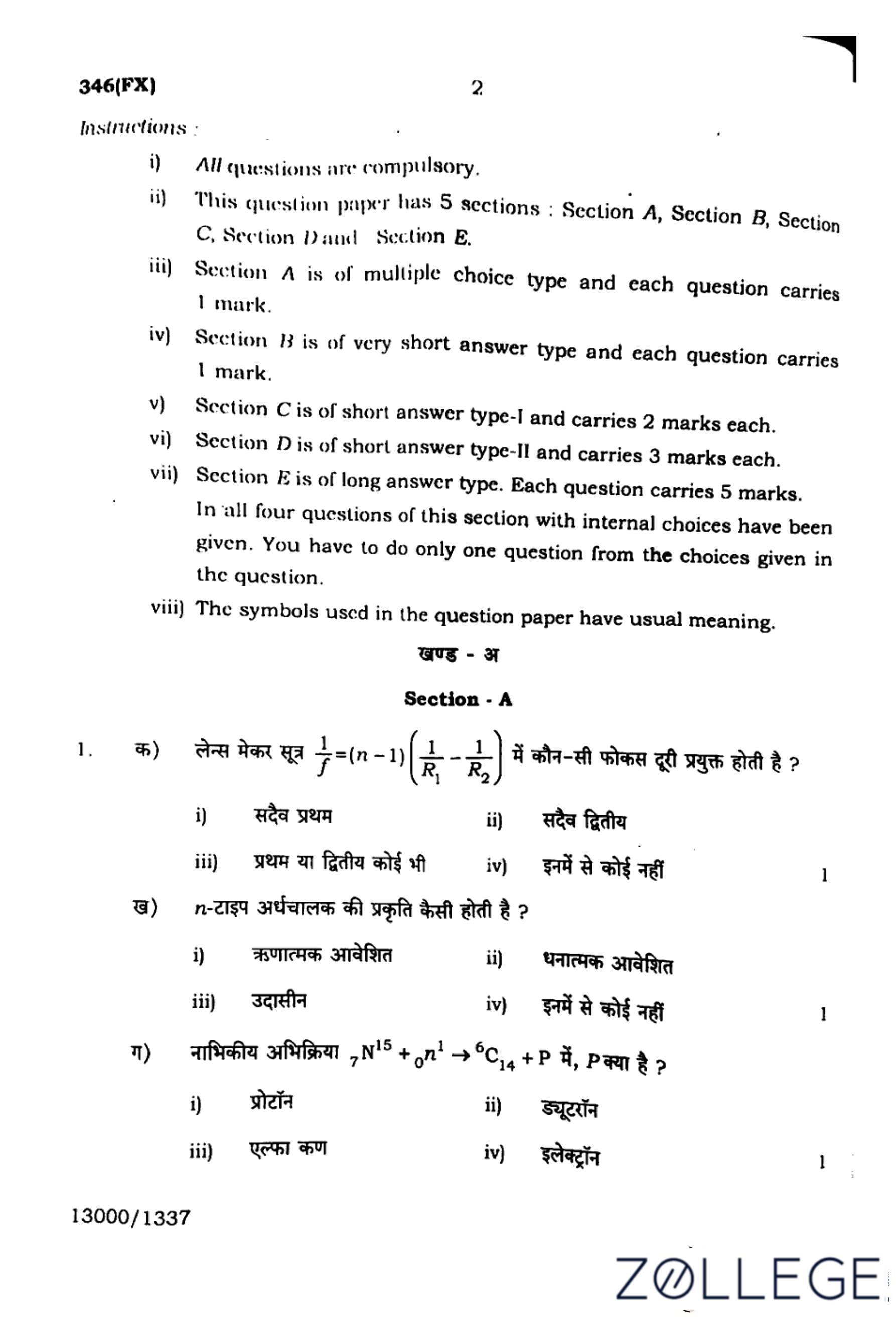
In lens maker formula \( \frac{1}{f} = (n-1) \left( \frac{1}{R_1} - \frac{1}{R_2} \right) \), which focal length is used?
View Solution
Step 1: The lens maker's formula is given as:
\[ \frac{1}{f} = (n-1) \left( \frac{1}{R_1} - \frac{1}{R_2} \right) \]
Step 2: Here, \( R_1 \) and \( R_2 \) are the radii of curvature of the two lens surfaces. The sign convention is used to determine which radius corresponds to the first and second surfaces.
Step 3: Generally, the formula considers the second focal length in practical applications as it corresponds to the image formation side.
\[ \therefore The correct answer is Always second. \]
\[ \boxed{Always second} \] Quick Tip: Always consider the lens maker's formula with proper sign convention and determine the focal length based on whether the lens is convex or concave.
What is the nature of n-type semiconductor?
View Solution
Step 1: An n-type semiconductor is created by doping a pure semiconductor with elements having more electrons.
Step 2: Despite having free electrons, the overall charge of the semiconductor remains neutral because the number of positive protons in the nuclei balances the charge.
\[ \therefore The correct answer is Neutral. \]
\[ \boxed{Neutral} \] Quick Tip: N-type semiconductors are neutral overall, even though they contain free electrons as charge carriers.
In nuclear reaction, \( _{7}^{15}N + _{0}^{1}n \rightarrow _{6}^{14}C + P \), what is P?
View Solution
Step 1: Analyze the given nuclear reaction:
\[ _{7}^{15}N + _{0}^{1}n \rightarrow _{6}^{14}C + P \]
Step 2: By balancing atomic and mass numbers:
\[ 7 + 0 = 6 + X \quad \Rightarrow \quad X = 1 \quad (Proton) \]
\[ 15 + 1 = 14 + Y \quad \Rightarrow \quad Y = 2 \quad (Mass of proton) \]
\[ \therefore The correct answer is Proton. \]
\[ \boxed{Proton} \] Quick Tip: In nuclear reactions, balance both atomic and mass numbers to identify unknown particles.
The equivalent resistance of 5 equal resistances connected in series and parallel are \( R_1 \) and \( R_2 \) respectively. If \( R_1 = nR_2 \), then what will be the possible value of \( n \)?
View Solution
Step 1: Equivalent resistance for resistors in series:
\[ R_1 = 5R \]
Step 2: Equivalent resistance for resistors in parallel:
\[ \frac{1}{R_2} = \frac{1}{R} + \frac{1}{R} + \frac{1}{R} + \frac{1}{R} + \frac{1}{R} \]
\[ R_2 = \frac{R}{5} \]
Step 3: Given \( R_1 = nR_2 \):
\[ 5R = n \cdot \frac{R}{5} \]
\[ n = 25 \]
\[ \therefore The correct answer is 25. \]
\[ \boxed{25} \] Quick Tip: For resistors in series, simply add their resistances; for parallel resistors, sum their reciprocals and take the inverse.
Which of the following is the unit of electric flux?
View Solution
Step 1: Electric flux is given by the formula:
\[ \Phi_E = \mathbf{E} \cdot \mathbf{A} \]
Step 2: The unit of electric field \( E \) is volt per metre (\( V/m \)), and the unit of area \( A \) is metre squared (\( m^2 \)).
\[ Unit of flux = \left( \frac{volt}{metre} \right) \times metre^2 = volt \times metre \]
\[ \therefore The correct answer is volt × metre. \]
\[ \boxed{volt × metre} \] Quick Tip: Remember that electric flux is the product of electric field strength and surface area, leading to the unit \( volt \times metre \).
If the resistance of ammeter and milli-ammeter are \( x_1 \) and \( x_2 \) respectively, then:
View Solution
Step 1: An ammeter is designed to measure larger currents with lower resistance, whereas a milli-ammeter measures smaller currents and therefore requires higher sensitivity.
Step 2: Since a milli-ammeter is more sensitive, it has higher internal resistance compared to an ammeter.
\[ \therefore x_1 < x_2 \]
\[ \boxed{x_1 < x_2} \] Quick Tip: Milli-ammeters have higher resistance than regular ammeters because they are designed for lower current measurements.
Write the relation between SI and MKS units of electric power.
View Solution
Step 1: In the SI system, electric power is measured in watts (W), where:
\[ 1 watt = 1 joule/second \]
Step 2: In the MKS system, power is also expressed in terms of mechanical energy per unit time, which leads to the same value.
\[ \therefore The relation is 1 watt = 1 joule per second. \]
\[ \boxed{1 watt = 1 joule/second} \] Quick Tip: Power in the SI and MKS systems is numerically the same, with both units related to energy conversion per second.
Which type of field is produced around a current carrying conductor and why?
View Solution
Step 1: When current flows through a conductor, it generates a magnetic field around it according to Ampere's circuital law.
Step 2: The right-hand rule helps determine the direction of the magnetic field, which forms concentric circles around the conductor.
\[ \therefore The field produced is a magnetic field. \]
\[ \boxed{Magnetic field} \] Quick Tip: Use the right-hand thumb rule to determine the direction of the magnetic field around a current-carrying conductor.
If \( \varepsilon_0 \) and \( \mu_0 \) represent permittivity and permeability of free space, then \( \frac{1}{\sqrt{\varepsilon_0 \mu_0}} \) represents which physical quantity?
View Solution
Step 1: The speed of electromagnetic waves in free space is given by the formula:
\[ c = \frac{1}{\sqrt{\varepsilon_0 \mu_0}} \]
Step 2: The values of permittivity \( \varepsilon_0 \) and permeability \( \mu_0 \) in free space determine the propagation speed of light.
\[ \therefore The correct answer is the speed of light. \]
\[ \boxed{Speed of light} \] Quick Tip: The relation \( c = \frac{1}{\sqrt{\varepsilon_0 \mu_0}} \) is fundamental in electromagnetism and defines the speed of light in vacuum.
How are optical ray and wavefront related with each other?
View Solution
Step 1: A wavefront represents the locus of points having the same phase in a wave.
Step 2: An optical ray indicates the direction of propagation of the wave.
Step 3: The optical ray is always perpendicular to the wavefront at any given point.
\[ \therefore The correct answer is: An optical ray is perpendicular to the wavefront. \]
\[ \boxed{An optical ray is perpendicular to the wavefront} \] Quick Tip: To understand wave behavior, remember that optical rays are always normal to wavefronts, following Huygens' principle.
Define energy band in solids.
View Solution
Step 1: In solids, atomic energy levels overlap due to the close proximity of atoms, forming continuous ranges called energy bands.
Step 2: The two main types of bands in a solid are the valence band (occupied by electrons) and the conduction band (where free electrons exist).
Step 3: The gap between these bands determines the electrical properties of the material.
\[ \therefore Energy bands define the allowed energy levels in a solid. \]
\[ \boxed{Energy bands are ranges of electron energy levels in solids.} \] Quick Tip: In semiconductors and insulators, the energy gap between valence and conduction bands determines their conductivity.
Who discovered the photoelectric effect?
View Solution
Step 1: The photoelectric effect is the phenomenon in which light incident on a metal surface ejects electrons.
Step 2: Albert Einstein explained this effect by proposing the quantization of light energy in the form of photons.
Step 3: This discovery confirmed the particle nature of light and won Einstein the Nobel Prize in Physics in 1921.
\[ \therefore The correct answer is: Albert Einstein. \]
\[ \boxed{Albert Einstein} \] Quick Tip: Remember that the photoelectric effect supports the quantum theory of light, leading to the concept of photons.
A capacitor of capacity \(10 \, \mu F\) is charged with a source of \(2\) volt. Calculate (i) the energy obtained from the source and (ii) the energy stored in the capacitor.
View Solution
Step 1: The total energy supplied by the source is calculated using:
\[ Energy = CV^2 \]
\[ = (10 \times 10^{-6}) (2)^2 \]
\[ = 4 \times 10^{-5} \, J \]
Step 2: The energy stored in the capacitor is:
\[ Stored Energy = \frac{1}{2} CV^2 \]
\[ = \frac{1}{2} (10 \times 10^{-6}) (2)^2 \]
\[ = 2 \times 10^{-5} \, J \]
\[ \therefore The correct answers are 4 \times 10^{-5} \, J and 2 \times 10^{-5} \, J. \]
\[ \boxed{4 \times 10^{-5} \, J, \, 2 \times 10^{-5} \, J} \] Quick Tip: In capacitors, only half of the energy supplied by the source is stored; the rest is dissipated in the circuit.
A cell has electromotive force \(1.5\) volt and internal resistance \(0.2\) ohm. It is connected with an external resistance of \(2.8\) ohm. Calculate (i) the potential difference across the open ends of the cell and (ii) the current obtained from the cell.
View Solution
Step 1: Using Ohm's Law, total resistance is:
\[ R_{total} = 0.2 + 2.8 = 3 \, \Omega \]
Step 2: The current obtained from the cell:
\[ I = \frac{E}{R_{total}} = \frac{1.5}{3} = 0.5 \, A \]
Step 3: Potential difference across the terminals:
\[ V = E - Ir = 1.5 - (0.5 \times 0.2) \]
\[ = 1.4 \, V \]
\[ \therefore The correct answers are 1.4 \, V and 0.5 \, A. \]
\[ \boxed{1.4 \, V, \, 0.5 \, A} \] Quick Tip: Always include internal resistance when calculating the total circuit resistance in practical cells.
If wavelength \( \lambda \) represents wave property and momentum \( p \) represents the particle property, then what will the expressions \( \lambda = \frac{h}{p} \) and \( p = \frac{h}{\lambda} \) represent?
View Solution
Step 1: The expression \( \lambda = \frac{h}{p} \) represents the de Broglie wavelength, which describes the wave nature of particles.
Step 2: The expression \( p = \frac{h}{\lambda} \) represents the particle's momentum derived from its wavelength.
\[ \therefore The correct answers are de Broglie wavelength and momentum. \]
\[ \boxed{de Broglie wavelength, momentum} \] Quick Tip: De Broglie's equation shows the wave-particle duality, linking wavelength with momentum.
If the mass defect of a nucleus is \(2 \times 10^{-6}\) kg, then calculate its binding energy in (i) joule and (ii) electron-volt.
View Solution
Step 1: The binding energy is calculated using Einstein’s equation:
\[ E = mc^2 \]
\[ = (2 \times 10^{-6}) (3 \times 10^8)^2 \]
\[ = 1.8 \times 10^{11} \, J \]
Step 2: Converting joules to electron-volts:
\[ 1 J = 6.24 \times 10^{18} eV \]
\[ E = 1.8 \times 10^{11} \times 6.24 \times 10^{18} \]
\[ = 1.12 \times 10^{30} \, eV \]
\[ \therefore The correct answers are 1.8 \times 10^{11} J and 1.12 \times 10^{30} eV. \]
\[ \boxed{1.8 \times 10^{11} J, \, 1.12 \times 10^{30} eV} \] Quick Tip: Use \( E = mc^2 \) to calculate binding energy, and remember the conversion factor \( 1 \, J = 6.24 \times 10^{18} eV \).
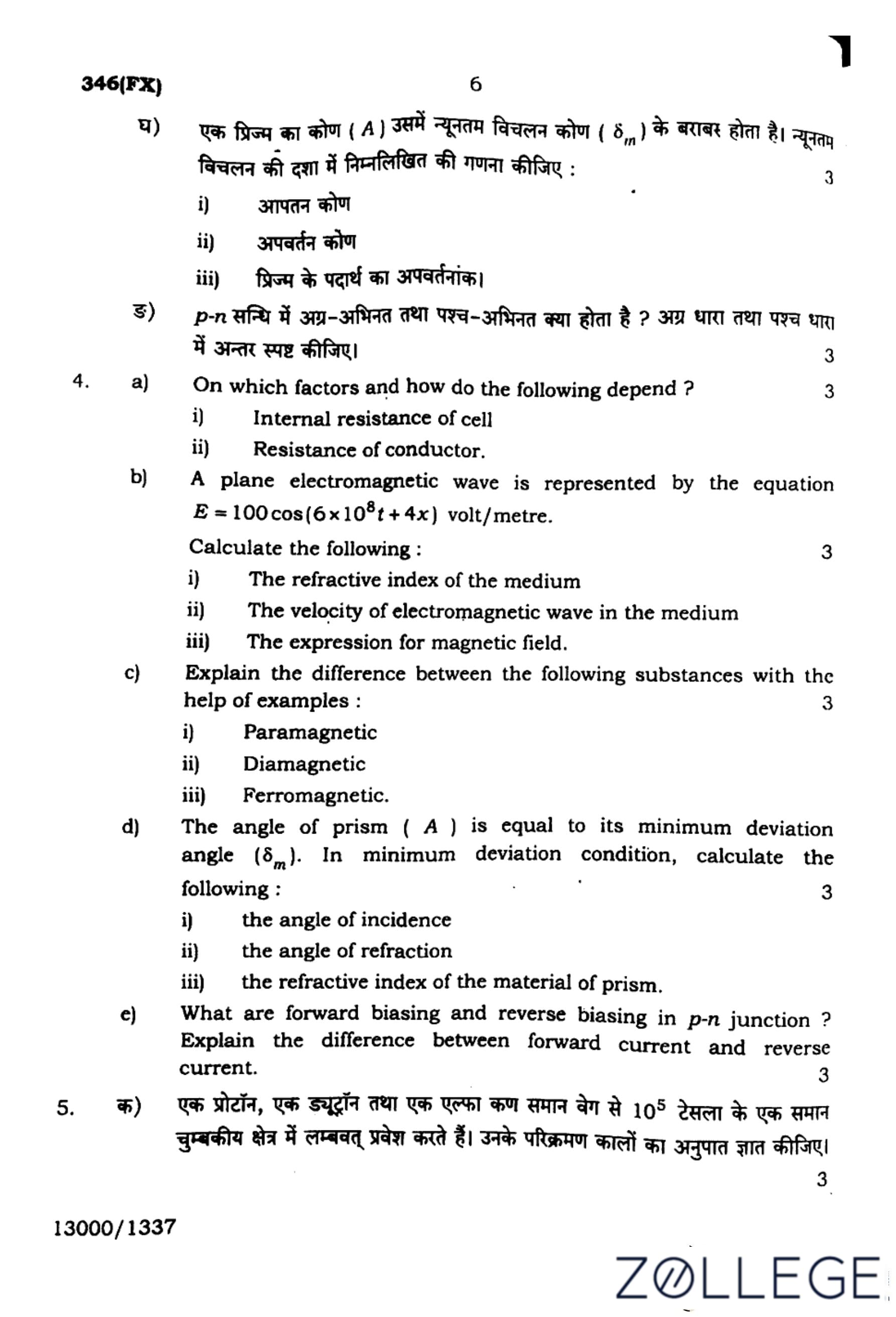
On which factors and how do the following depend?
(i) Internal resistance of cell
(ii) Resistance of conductor
View Solution
i. Internal resistance of cell
Step 1: The internal resistance of a cell depends on several factors:
\[ r \propto \frac{distance between electrodes}{area of electrodes} \]
- It increases if the distance between electrodes increases.
- It decreases if the cross-sectional area of electrodes increases.
- It depends on the electrolyte's concentration and nature.
\[ Thus, the internal resistance can be minimized by using a highly conductive electrolyte and optimizing electrode placement. \]
\[ \boxed{Factors: Distance, area, electrolyte nature, and temperature} \]
\hrule
ii. Resistance of conductor
Step 1: The resistance of a conductor is given by:
\[ R = \rho \frac{L}{A} \]
where:
- \( R \) is resistance,
- \( \rho \) is resistivity,
- \( L \) is length,
- \( A \) is cross-sectional area.
Step 2: Factors affecting resistance:
- It increases with an increase in length (\( L \)).
- It decreases with an increase in cross-sectional area (\( A \)).
- Different materials have different resistivities.
- Resistance increases with temperature due to an increase in resistivity.
\[ Therefore, resistance can be controlled by choosing appropriate materials and dimensions. \]
\[ \boxed{Factors: Length, cross-sectional area, material, and temperature} \] Quick Tip: To reduce conductor resistance, choose materials with low resistivity and increase the cross-sectional area.
A plane electromagnetic wave is represented by the equation
\[ E = 100 \cos(6 \times 10^8 t + 4x) \, volt/metre. \]
Calculate the following:
(i) The refractive index of the medium
(ii) The velocity of electromagnetic wave in the medium
(iii) The expression for magnetic field
View Solution
i. The refractive index of the medium
Step 1: The given equation of the wave is:
\[ E = 100 \cos(6 \times 10^8 t + 4x) \]
Step 2: Comparing with the general wave equation \( E = E_0 \cos(\omega t + kx) \), we get:
\[ \omega = 6 \times 10^8, \quad k = 4 \]
Step 3: Using the relation \( v = \frac{\omega}{k} \):
\[ v = \frac{6 \times 10^8}{4} = 1.5 \times 10^8 \, m/s \]
Step 4: The refractive index is:
\[ n = \frac{c}{v} = \frac{3 \times 10^8}{1.5 \times 10^8} = 2 \]
\[ \boxed{n = 2} \]
ii. The velocity of electromagnetic wave in the medium
Step 1: From the previous step, we obtained the velocity as:
\[ v = \frac{\omega}{k} = 1.5 \times 10^8 \, m/s \]
\[ \boxed{v = 1.5 \times 10^8 \, m/s} \]
iii. The expression for magnetic field
Step 1: In an electromagnetic wave, the magnetic field \( B \) is related to the electric field \( E \) by:
\[ B = \frac{E}{c} \]
Step 2: Substituting the given electric field expression:
\[ B = \frac{100}{3 \times 10^8} \cos(6 \times 10^8 t + 4x) \]
\[ B = \frac{E_0}{c} \cos(6 \times 10^8 t + 4x) \]
\[ \boxed{B = \frac{E_0}{c} \cos(6 \times 10^8 t + 4x)} \] Quick Tip: For plane electromagnetic waves, the velocity can be calculated using \( v = \frac{\omega}{k} \) and the magnetic field using \( B = \frac{E}{c} \).
Explain the difference between the following substances with the help of examples:
(i) Paramagnetic
(ii) Diamagnetic
(iii) Ferromagnetic
View Solution
i. Paramagnetic Substances
Step 1: Paramagnetic materials have unpaired electrons in their atomic structure, which cause weak attraction to external magnetic fields.
Step 2: They have a small and positive magnetic susceptibility and align weakly with the applied magnetic field.
Examples: Aluminum, Platinum, Oxygen.
\[ \boxed{Weak attraction, e.g., Aluminum} \]
ii. Diamagnetic Substances
Step 1: Diamagnetic materials have all paired electrons, causing them to create an induced magnetic field in the opposite direction to the applied field.
Step 2: They have a small and negative magnetic susceptibility and are weakly repelled by the applied magnetic field.
Examples: Copper, Gold, Bismuth.
\[ \boxed{Weak repulsion, e.g., Copper} \]
iii. Ferromagnetic Substances
Step 1: Ferromagnetic materials have domains of atoms that align strongly with an external magnetic field, creating a strong attraction.
Step 2: They have high positive susceptibility and retain magnetization even after removing the external field.
Examples: Iron, Nickel, Cobalt.
\[ \boxed{Strong attraction, e.g., Iron} \] Quick Tip: Ferromagnetic materials retain magnetism, while paramagnetic and diamagnetic materials do not.
The angle of prism (A) is equal to its minimum deviation angle (\( \delta_m \)). In minimum deviation condition, calculate the following:
(i) The angle of incidence
(ii) The angle of refraction
(iii) The refractive index of the material of the prism.
View Solution
i. The angle of incidence
Step 1: At minimum deviation condition, the angle of incidence \( i \) is related to the prism angle \( A \) and minimum deviation angle \( \delta_m \) by:
\[ i = A + \frac{\delta_m}{2} \]
Step 2: Given \( A = \delta_m \), we substitute:
\[ i = A + \frac{A}{2} = \frac{3A}{2} \]
\[ \boxed{i = \frac{3A}{2}} \]
ii. The angle of refraction
Step 1: At minimum deviation, the refracted ray passes symmetrically through the prism, meaning:
\[ r = \frac{A}{2} \]
\[ \boxed{r = \frac{A}{2}} \]
iii. The refractive index of the material of the prism
Step 1: The refractive index \( n \) of the prism material is given by:
\[ n = \frac{\sin \left( \frac{A + \delta_m}{2} \right)}{\sin \left( \frac{A}{2} \right)} \]
Step 2: Since \( A = \delta_m \):
\[ n = \frac{\sin \left( \frac{A + A}{2} \right)}{\sin \left( \frac{A}{2} \right)} \]
\[ n = \frac{\sin A}{\sin \left( \frac{A}{2} \right)} \]
\[ \boxed{n = \frac{\sin A}{\sin \left( \frac{A}{2} \right)}} \] Quick Tip: In minimum deviation condition, the refracted ray is symmetric inside the prism, and refractive index can be calculated using the formula \( n = \frac{\sin \left( \frac{A + \delta_m}{2} \right)}{\sin \left( \frac{A}{2} \right)} \).
What are forward biasing and reverse biasing in \( p-n \) junction? Explain the difference between forward current and reverse current.
View Solution
Step 1: Forward Biasing
In forward biasing, the external voltage applied reduces the potential barrier of the depletion region, allowing current to flow easily through the junction.
- The positive terminal of the battery is connected to the \( p \)-side, and the negative terminal to the \( n \)-side.
- As the barrier potential decreases, more charge carriers (electrons and holes) cross the junction.
- The current increases exponentially with applied voltage.
Example: Forward biasing is used in rectifiers and LEDs.
\[ Current in forward bias I_F \propto e^{\frac{V}{kT}} \]
\[ \boxed{Forward bias allows current flow.} \]
Step 2: Reverse Biasing
In reverse biasing, the external voltage increases the potential barrier, preventing the flow of majority carriers and widening the depletion region.
- The positive terminal is connected to the \( n \)-side, and the negative terminal to the \( p \)-side.
- Only a small leakage current flows due to minority carriers.
- Beyond a certain voltage, breakdown occurs, causing a large current to flow.
Example: Reverse biasing is used in Zener diodes and photodiodes.
\[ Reverse current I_R \approx 0 \]
\[ \boxed{Reverse bias restricts current flow.} \]
Step 3: Difference Between Forward and Reverse Current
| Forward Current | Reverse Current |
|---|---|
| Large current flow | Very small current flow (leakage current) |
| Depletion region shrinks | Depletion region widens |
| Used in conduction applications | Used for blocking applications |
\[ \boxed{Forward current is significant; reverse current is minimal.} \] Quick Tip: In practical applications, forward biasing allows current flow in diodes, while reverse biasing is used for blocking and sensing applications.
A proton, a deuteron and an alpha particle of same velocity enter perpendicularly in an uniform magnetic field of \( 10^5 \) tesla. Calculate the ratio of their time periods of revolution.
View Solution
Step 1: The time period of a charged particle in a magnetic field is given by the formula:
\[ T = \frac{2\pi m}{q B} \]
Step 2: Given that the velocity and magnetic field are the same for all particles, the ratio of time periods depends on the ratio \( \frac{m}{q} \).
Step 3: The mass and charge values of the particles:
\[ Proton: m_p, \quad q_p = e \]
\[ Deuteron: m_d = 2m_p, \quad q_d = e \]
\[ Alpha particle: m_{\alpha} = 4m_p, \quad q_{\alpha} = 2e \]
Step 4: Using the formula \( T \propto \frac{m}{q} \):
\[ \frac{T_{proton}}{T_{deuteron}} = \frac{m_p/e}{2m_p/e} = \frac{1}{2} \]
\[ \frac{T_{proton}}{T_{\alpha}} = \frac{m_p/e}{4m_p/2e} = \frac{1}{4} \]
Thus, the ratio of time periods is:
\[ 1:2:4 \]
\[ \boxed{1:2:4} \] Quick Tip: The time period of a charged particle in a magnetic field is proportional to the mass-to-charge ratio \( \frac{m}{q} \).
Calculate the following for the given circuit:

(ii) \( V_R = 200 \, V \)
(iii) \( 180^\circ \)
View Solution
Given:
Resistance \( R = 400 \, \Omega \), Inductive voltage \( V_L = 120 \, V \), Capacitive voltage \( V_C = 120 \, V \), and source voltage:
\[ V = 200 \cos(50\pi t) \, volt \]
(i) Current in the circuit
Step 1: The impedance of the circuit:
Since the inductor and capacitor voltages are equal, they cancel each other out, leaving only the resistance.
Step 2: Applying Ohm's law:
\[ I = \frac{V}{R} \]
\[ = \frac{200}{400} \]
\[ = 0.5 \, A \]
\[ \boxed{I = 0.5 \, A} \]
(ii) The potential across resistance
Step 1: Using Ohm's law to find the potential across the resistor:
\[ V_R = IR \]
\[ = (0.5)(400) \]
\[ = 200 \, V \]
\[ \boxed{V_R = 200 \, V} \]
(iii) The phase difference between the potentials across inductor and capacitor
Step 1: In an LC circuit, the voltage across the inductor leads the current by \(90^\circ\), while the voltage across the capacitor lags the current by \(90^\circ\).
Step 2: Therefore, the phase difference between the inductor and capacitor voltages is:
\[ \theta = 90^\circ + 90^\circ = 180^\circ \]
\[ \boxed{180^\circ} \] Quick Tip: In an LC circuit, inductor voltage leads the current by \( 90^\circ \), and capacitor voltage lags by \( 90^\circ \), resulting in a \( 180^\circ \) phase difference.
In a spherical mirror, the distance between the focus point and centre of curvature is \( 20 \, cm \). Calculate the following and write their names:
(i) The distance of pole of mirror from its focal point.
(ii) The distance of pole of mirror from its centre of curvature.
(i) The distance of pole of mirror from its focal point
(II)\( 40 \, cm \) (Radius of curvature)
View Solution
Step 1: The focal length \( f \) of a spherical mirror is the distance between the pole and the focal point.
Step 2: Given that the distance between the focus and centre of curvature is \( 20 \, cm \), we know that:
\[ f = 20 \, cm \]
\[ \boxed{20 \, cm (Focal length)} \]
(ii) The distance of pole of mirror from its centre of curvature
\( 40 \, cm \) (Radius of curvature)
Step 1: The radius of curvature \( R \) is the distance between the pole and the centre of curvature.
Step 2: Since the focal length is given as \( f = 20 \, cm \), we use the relation:
\[ R = 2f \]
Step 3: Substituting the given value:
\[ R = 2 \times 20 = 40 \, cm \]
\[ \boxed{40 \, cm (Radius of curvature)} \] Quick Tip: In spherical mirrors, the focal length is half of the radius of curvature, given by \( f = \frac{R}{2} \). The radius of curvature is always twice the focal length in spherical mirrors.
What is meant by threshold wavelength \( \lambda_0 \) and threshold frequency \( \nu_0 \) in photoelectric effect? On which factors do the saturation current and the value of cut-off voltage depend?
View Solution
Step 1: Threshold Wavelength and Threshold Frequency
Threshold Wavelength:
Threshold wavelength \( \lambda_0 \) is the longest wavelength of incident light that can cause photoemission. It is related to the work function \( \phi \) of the material by the equation:
\[ \lambda_0 = \frac{hc}{\phi} \]
If the wavelength \( \lambda \) of the incident light is greater than \( \lambda_0 \), photoemission does not occur.
Threshold Frequency:
Threshold frequency \( \nu_0 \) is the minimum frequency of the incident light required to eject electrons from the metal surface. It is given by:
\[ \nu_0 = \frac{\phi}{h} \]
If the frequency \( \nu \) of the incident light is less than \( \nu_0 \), no photoelectric emission occurs.
\[ \boxed{\lambda_0 = \frac{hc}{\phi}, \quad \nu_0 = \frac{\phi}{h}} \]
Step 2: Factors affecting Saturation Current and Cut-off Voltage
Saturation Current:
Saturation current is the maximum current obtained when all photoelectrons emitted from the surface reach the anode. It depends on:
- Intensity of Incident Light: As the intensity increases, more photons strike the surface, resulting in the emission of more electrons.
\[ Saturation current \propto Intensity of light \]
Cut-off Voltage:
Cut-off voltage (stopping potential) is the minimum negative potential required to stop the photoelectrons from reaching the anode. It depends on:
- Frequency of Incident Light: Higher frequency photons carry more energy, requiring a higher cut-off voltage to stop the electrons.
Using Einstein's photoelectric equation:
\[ eV_{cut-off} = h\nu - \phi \]
\[ \boxed{Saturation current \propto intensity, \quad V_{cut-off} \propto frequency.} \] Quick Tip: Remember: Saturation current depends on light intensity, whereas cut-off voltage is determined by light frequency and the material's work function.
What is \( p-n \) junction rectifier? Draw circuit diagram of (i) half-wave rectifier (HWR) and (ii) full-wave rectifier (FWR).
View Solution
(i) Half-Wave Rectifier (HWR)
Step 1: In a half-wave rectifier, a single diode is used to allow the flow of current only during the positive half of the AC input.
Step 2: During the negative half-cycle, the diode blocks the current flow.
\[ \boxed{HWR allows current in one half-cycle.} \]
(ii) Full-Wave Rectifier (FWR)
Step 1: A full-wave rectifier uses two diodes (center-tap transformer) or four diodes (bridge rectifier) to allow current in both positive and negative cycles.
Step 2: This results in a pulsating DC output.
\[ \boxed{FWR allows current in both half-cycles.} \] Quick Tip: A half-wave rectifier uses one diode, while a full-wave rectifier uses two or four diodes for continuous current flow.
OR
Question 5.e:
Compare \( n \)-type and \( p \)-type semiconductors on the basis of the following:
(i) The nature of doping material
(ii) Majority and minority charge carriers
(iii) The relation between conductivity and mobility
View Solution
(i) The nature of doping material
- In \( n \)-type semiconductors, donor atoms with 5 valence electrons provide extra electrons.
- In \( p \)-type semiconductors, acceptor atoms with 3 valence electrons create holes.
\[ \boxed{Pentavalent for n-type, Trivalent for p-type} \]
(ii) Majority and minority charge carriers
- In \( n \)-type semiconductors, electrons contribute to conduction.
- In \( p \)-type semiconductors, holes dominate conduction.
\[ \boxed{Electrons in n-type, Holes in p-type} \]
(iii) The relation between conductivity and mobility
Step 1: The conductivity \( \sigma \) is given by:
\[ \sigma = nq\mu \]
where:
- \( n \) is the number of charge carriers,
- \( q \) is the charge of the carriers,
- \( \mu \) is the mobility of the carriers.
Step 2: Since electrons have higher mobility than holes:
\[ \mu_n > \mu_p \Rightarrow \sigma_n > \sigma_p \]
\[ \boxed{\sigma_n > \sigma_p} \] Quick Tip: Conductivity increases with higher charge carrier concentration and mobility.
When a capacitor of capacity \( C \) is charged with charge \( q \) and potential difference \( V \), the electric field \( E \) and the electrostatic energy \( U \) is obtained between plates of capacitor. If the capacitor is disconnected from the source and a slab of medium having the same thickness and dielectric constant \( k \) is introduced completely between the plates, calculate the new values of the following:
(i)Capacity
(ii) Potential difference
(iii) Charge
(iv) Electric field
(v) Electrostatic potential energy
(I) \( C' = kC \)
(II) \( V' = \frac{V}{k} \)
(III) \( q' = q \) (remains constant)
(IV)\( E' = \frac{E}{k} \)
(V) \( U' = \frac{U}{k} \)
View Solution
(i) Capacity
Step 1: The capacitance of a parallel plate capacitor with dielectric is given by:
\[ C' = kC \]
\[ \boxed{C' = kC} \]
(ii) Potential Difference
Step 1: Since the capacitor is disconnected, the charge remains constant. Using the formula:
\[ V' = \frac{q}{C'} = \frac{q}{kC} \]
\[ V' = \frac{V}{k} \]
\[ \boxed{V' = \frac{V}{k}} \]
(iii) Charge
\( q' = q \) (remains constant)
Step 1: As the capacitor is disconnected, the charge remains the same:
\[ q' = q \]
\[ \boxed{q' = q} \]
(iv) Electric Field
\( E' = \frac{E}{k} \)
Step 1: The electric field is given by:
\[ E = \frac{V}{d} \]
Step 2: Substituting the new potential difference:
\[ E' = \frac{V'}{d} = \frac{V}{kd} \]
\[ E' = \frac{E}{k} \]
\[ \boxed{E' = \frac{E}{k}} \]
(v) Electrostatic Potential Energy
\( U' = \frac{U}{k} \)
Step 1: Electrostatic potential energy is given by:
\[ U = \frac{1}{2} C V^2 \]
Step 2: Substituting new values:
\[ U' = \frac{1}{2} kC \left( \frac{V}{k} \right)^2 \]
\[ U' = \frac{U}{k} \]
\[ \boxed{U' = \frac{U}{k}} \] Quick Tip: When a dielectric is inserted, the capacitance increases by a factor of \( k \), while the potential and electric field decrease proportionally.
OR
Question 6:
What is the main difference between a cell and a battery? In which conditions do the following combinations of cells become useful and why?
(i) Series combination
(ii) Parallel combination
(iii) Mixed combination
Main difference between a cell and a battery
In a parallel combination, the current increases while the voltage remains the same.
A mixed combination provides both higher voltage and higher current.
View Solution
Step 1: A cell generates electrical energy from a chemical reaction within a single unit.
Step 2: A battery consists of multiple interconnected cells to provide higher output for more demanding applications.
\[ \boxed{Cell: Single unit, Battery: Multiple cells} \]
(i) Series Combination
In a series combination, the voltages add up while the current remains the same.
Step 1: Cells are connected end-to-end, with the positive terminal of one connected to the negative terminal of the next.
Step 2: The total voltage is:
\[ V_{total} = V_1 + V_2 + V_3 + \dots \]
Step 3: This configuration is useful when high voltage is required, such as in electronic circuits.
\[ \boxed{Used for high voltage applications.} \]
\hrule
(ii) Parallel Combination
Step 1: Cells are connected with all positive terminals together and all negative terminals together.
Step 2: The total current is:
\[ I_{total} = I_1 + I_2 + I_3 + \dots \]
Step 3: This configuration is useful when a higher current capacity is needed, such as in power backup systems.
\[ \boxed{Used for high current applications.} \]
(iii) Mixed Combination
Step 1: In mixed combination, cells are connected in both series and parallel configurations.
Step 2: This provides an increase in both voltage and current, depending on the number of cells.
Step 3: It is useful in applications where both high voltage and current are needed, such as in electric vehicles.
\[ \boxed{Used for balanced voltage and current applications.} \] Quick Tip: Series combination increases voltage, parallel combination increases current, and mixed combination balances both.
The focal lengths of a convergent and a divergent lens are \( f_1 \) and \( f_2 \) respectively. If the lenses are placed in contact, then in the following conditions of combination, write the nature of the combined lens and also draw the ray diagram:
(i) \( f_1 > f_2 \)
(ii) \( f_1 < f_2 \)
(iii) \( f_1 = f_2 \)
View Solution
(i) Condition: \( f_1 > f_2 \)
Step 1: The effective focal length of the lens combination is given by:
\[ \frac{1}{F} = \frac{1}{f_1} + \frac{1}{f_2} \]
Step 2: Since \( f_1 > f_2 \) and \( f_2 \) is negative for a diverging lens:
\[ \frac{1}{F} = \frac{1}{f_1} - \frac{1}{|f_2|} \]
Step 3: If \( f_1 \) dominates, the net effect is converging.
\[ \boxed{Combination acts as a converging lens.} \]
(ii) Condition: \( f_1 < f_2 \)
Step 1: Using the same formula:
\[ \frac{1}{F} = \frac{1}{f_1} + \frac{1}{f_2} \]
Step 2: If \( f_1 < f_2 \), the negative focal length of the diverging lens dominates.
\[ \frac{1}{F} < 0 \]
Step 3: The net effect is a diverging lens.
\[ \boxed{Combination acts as a diverging lens.} \]
(iii) Condition: \( f_1 = f_2 \)
Step 1: Using the lens formula:
\[ \frac{1}{F} = \frac{1}{f_1} + \frac{1}{f_2} \]
Step 2: If \( f_1 \) and \( f_2 \) are equal in magnitude but opposite in sign:
\[ \frac{1}{F} = 0 \Rightarrow F = \infty \]
Step 3: The combination acts as a plane parallel glass.
\[ \boxed{Combination acts as a plane glass.} \] Quick Tip: The focal length of a lens combination is determined by the sum of reciprocals of individual focal lengths.
OR
Question 7:
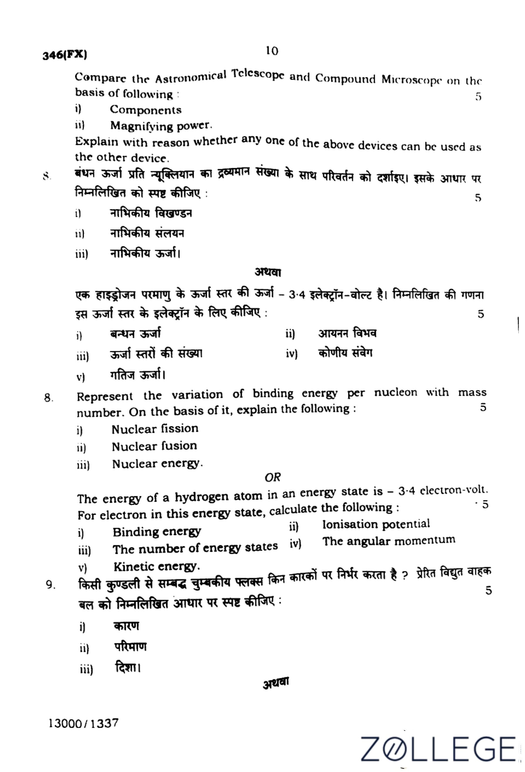
Compare the Astronomical Telescope and Compound Microscope on the basis of the following:
(i) Components
(ii)Magnifying power
Explain with reason whether any one of the above devices can be used as the other device.
View Solution
(i) Components
An astronomical telescope consists of an objective lens and an eyepiece with a longer focal length, while a compound microscope consists of an objective lens and an eyepiece with a shorter focal length.
Astronomical Telescope:
- Used for viewing distant objects.
- Components:
- Objective lens: Large aperture, long focal length.
- Eyepiece lens: Shorter focal length for magnification.
Compound Microscope:
- Used for viewing tiny nearby objects.
- Components:
- Objective lens: Short focal length, higher magnification.
- Eyepiece lens: Further magnifies the intermediate image.
\[ \boxed{Telescope: Long focal length, Microscope: Short focal length.} \]
(ii) Magnifying Power
The magnifying power of an astronomical telescope is the ratio of focal lengths, while for a compound microscope, it is the product of magnifications of the objective and eyepiece lenses.
Astronomical Telescope:
\[ Magnifying Power = \frac{f_{objective}}{f_{eyepiece}} \]
Compound Microscope:
\[ Magnifying Power = m_{objective} \times m_{eyepiece} \]
Conclusion:
- Telescope magnifies distant objects by collecting more light.
- Microscope magnifies small objects by successive magnification.
\[ \boxed{Telescope: Focal length ratio, Microscope: Successive magnification.} \]
Can one device be used as the other?
A telescope is designed for distant objects with long focal length, while a microscope is designed for close objects with short focal length.
The image formation principles and optical configurations are different, making them unsuitable for interchange.
\[ Thus, one cannot be used as the other. \]
\[ \boxed{Telescope and microscope serve distinct purposes.} \] Quick Tip: Remember: Telescopes are for distant objects with long focal lengths, while microscopes magnify tiny objects with short focal lengths.
Represent the variation of binding energy per nucleon with mass number. On the basis of it, explain the following:
(i) Nuclear fission
(ii) Nuclear fusion
(iii) Nuclear energy
Binding Energy per Nucleon vs Mass Number
View Solution
Step 1: The binding energy per nucleon varies with mass number.
Step 2: The curve shows that lighter nuclei and very heavy nuclei have lower binding energy, while medium-sized nuclei (e.g., iron) have the highest binding energy, making them more stable.
\[ \boxed{Most stable nucleus: Fe (A = 56)} \]
(i) Nuclear Fission
Nuclear fission is the process where a heavy nucleus splits into smaller nuclei, releasing energy.
Step 1: Heavy elements such as uranium-235 split into lighter elements when bombarded with neutrons.
Step 2: This process releases energy due to the increase in binding energy per nucleon.
\[ \boxed{Heavy nucleus \rightarrow Two lighter nuclei + Energy} \]
(ii) Nuclear Fusion
Nuclear fusion is the process where lighter nuclei combine to form a heavier nucleus, releasing energy.
Step 1: Light elements such as hydrogen nuclei fuse together under high temperature and pressure to form helium.
Step 2: This results in a release of energy due to an increase in binding energy per nucleon.
\[ \boxed{Light nuclei \rightarrow Heavier nucleus + Energy} \]
(iii) Nuclear Energy
Nuclear energy is the energy released during fission or fusion due to changes in binding energy.
Step 1: The energy released during fission and fusion reactions is calculated using Einstein's equation:
\[ E = mc^2 \]
Step 2: This energy is harnessed in nuclear reactors and stars.
\[ \boxed{Energy is released due to mass defect.} \] Quick Tip: Nuclear fusion occurs in stars, while nuclear fission is used in power plants.
OR
Question 8:
The energy of a hydrogen atom in an energy state is \( -3.4 \) electron-volts. For an electron in this energy state, calculate the following:
(i) Binding energy
(ii) Ionization potential
(iii) The number of energy states
(iv) The angular momentum
(v) Kinetic energy
View Solution
(i) Binding energy
Binding energy is the energy required to remove the electron from the given state.
\[ Binding energy = 3.4 eV \]
\[ \boxed{3.4 eV} \]
(ii) Ionization Potential
Ionization potential is the energy required to ionize the atom by removing an electron from the current state.
\[ Ionization potential = 3.4 eV \]
\[ \boxed{3.4 eV} \]
(iii) The Number of Energy States
The number of possible states for an electron in the nth energy level is given by:
\[ Number of states = n^2 \]
For \( n = 2 \):
\[ 2^2 = 4 \]
\[ \boxed{4} \]
(iv) The Angular Momentum
The angular momentum of an electron in the nth orbit is:
\[ L = n \hbar \]
For \( n = 2 \):
\[ L = 2\hbar \]
\[ \boxed{2\hbar} \]
(v) Kinetic Energy
In hydrogen atoms, kinetic energy in an energy state is numerically equal to the binding energy.
\[ Kinetic Energy = 3.4 eV \]
\[ \boxed{3.4 eV} \] Quick Tip: For hydrogen atoms, ionization energy equals the binding energy in a given state.
On what factors does the magnetic flux linked with a coil depend? Explain the induced electromotive force on the basis of the following:
(i) Cause
(ii) Magnitude
(iii) Direction
Factors affecting magnetic flux linked with a coil
View Solution
Step 1: Magnetic flux (\( \Phi \)) linked with a coil depends on:
\[ \Phi = B A \cos \theta \]
where:
- \( B \) = Magnetic field strength
- \( A \) = Area of the coil
- \( \theta \) = Angle between the field and the normal to the coil
\[ \boxed{Flux depends on B, A, and \theta.} \]
(i) Cause
The changing magnetic field causes an induced electromotive force (EMF).
Step 1: According to Faraday's law, EMF is induced when the magnetic flux through a coil changes with time.
\[ \mathcal{E} = -\frac{d\Phi}{dt} \]
\[ \boxed{Changing flux induces EMF.} \]
(ii) Magnitude
The magnitude of induced EMF is proportional to the rate of change of flux.
Step 1: Using Faraday's law, the magnitude of the induced EMF is:
\[ |\mathcal{E}| = \left| \frac{d\Phi}{dt} \right| \]
Step 2: Faster changes in flux result in higher EMF.
\[ \boxed{\mathcal{E} \propto \frac{d\Phi}{dt}} \]
(iii) Direction
The direction of induced EMF is given by Lenz's Law.
Step 1: According to Lenz's Law, the induced EMF opposes the change in magnetic flux.
Step 2: The negative sign in Faraday's law signifies this opposition.
\[ \mathcal{E} = -\frac{d\Phi}{dt} \]
\[ \boxed{Opposes the flux change.} \] Quick Tip: Remember, a change in flux induces an EMF that opposes the cause producing it.
OR
Question 9:
On what principle does the transformer work? State the following conditions for an ideal transformer:
(i) Leakage of magnetic flux
(ii) Resistance of primary coil
(iii) Resistance of secondary coil
(iv)Dissipation of power
Principle of Transformer
View Solution
A transformer works on the principle of electromagnetic induction.
Step 1: An alternating current in the primary coil creates a changing magnetic field.
Step 2: This varying magnetic flux induces an EMF in the secondary coil according to Faraday's law.
\[ V_s = \frac{N_s}{N_p} V_p \]
\[ \boxed{Transformer works on mutual induction.} \]
Conditions for an ideal transformer
(i) Leakage of magnetic flux
There should be no flux leakage; all flux should link both coils.
Step 1: Ideally, all magnetic flux produced by the primary coil should pass through the secondary coil.
\[ \boxed{Zero flux leakage for ideal transformer.} \]
(ii) Resistance of primary coil
The primary coil should have zero resistance.
Step 1: An ideal transformer assumes no resistive losses in the primary coil to prevent energy dissipation.
\[ \boxed{Zero resistance in the primary coil.} \]
(iii) Resistance of secondary coil
The secondary coil should also have zero resistance.
Step 1: In an ideal transformer, the secondary coil is assumed to be perfect, with no resistance.
\[ \boxed{Zero resistance in the secondary coil.} \]
(iv) Dissipation of power
There should be no power loss in an ideal transformer.
Step 1: In an ideal transformer, the entire power input is transferred to the output.
Step 2: Efficiency is 100%, meaning no loss due to resistance, flux leakage, or core losses.
\[ \boxed{No power dissipation in ideal transformer.} \] Quick Tip: An ideal transformer assumes perfect energy transfer with no losses.


Comments