


UP Board Class 12 Physics Question Paper 2023 with Answer Key Code 346 BY is available for download. The exam was conducted by the Uttar Pradesh Madhyamik Shiksha Parishad (UPMSP) on March 1, 2023 in Afternoon Session 2 PM to 5:15 PM. The medium of paper was English and Hindi. In terms of difficulty level, UP Board Class 12 Physics paper was Easy. The question paper comprised a total of 9 questions.
UP Board Class 12 Physics (Code 346 BY) Question Paper 2023 with Solutions PDF
| UP Board Class 12 Physics Question Paper with Solutions PDF | Check Solutions |

The unit of electric flux is:
View Solution
Step 1: Formula of electric flux.
Electric flux is defined as: \[ \phi = \vec{E} \cdot \vec{A} \]
where \(\vec{E}\) is electric field (unit: Volt/m) and \(\vec{A}\) is area (\(m^2\)).
Step 2: Unit calculation.
So, unit = (Volt/m) \(\times\) (\(m^2\)) = Volt \(\times\) metre.
Step 3: Conclusion.
Thus, the correct answer is Volt \(\times\) metre. Quick Tip: Electric flux connects electric field with surface area. Its SI unit is Volt \(\times\) metre.
N-type semi-conductor is:
View Solution
Step 1: Nature of N-type semiconductor.
In N-type semiconductors, electrons are majority carriers. But for every extra electron, there is a positive ion core.
Step 2: Neutrality.
The number of positive and negative charges balance each other.
Step 3: Conclusion.
Hence, N-type semiconductors are overall electrically neutral. Quick Tip: N-type means negative charge carriers dominate, but overall the material remains neutral.
Electromagnetic waves are:
View Solution
Step 1: Nature of EM waves.
Electromagnetic waves consist of oscillating electric and magnetic fields.
Step 2: Orientation.
These fields are perpendicular to each other and also perpendicular to the direction of propagation.
Step 3: Conclusion.
Hence, EM waves are purely transverse. Quick Tip: In EM waves, \(E\), \(B\), and direction of propagation are mutually perpendicular.
Which colour of light has minimum deviation after passing white light through a prism?
View Solution
Step 1: Refraction through prism.
The deviation depends on refractive index, which varies with wavelength.
Step 2: Dispersion of light.
Red has the longest wavelength, so it bends the least. Violet has the shortest wavelength, so it bends the most.
Step 3: Conclusion.
Thus, red colour has minimum deviation. Quick Tip: In dispersion, violet deviates maximum, red deviates minimum.
The difference in angular momentum of electrons between two successive orbits of hydrogen atom is:
View Solution
Step 1: Bohr’s quantization rule.
Angular momentum of electron in orbit \(n\) is: \[ L = n \dfrac{h}{2\pi} \]
Step 2: Successive difference.
For two successive orbits: \[ L_{n+1} - L_n = \dfrac{h}{2\pi} \]
Step 3: Conclusion.
So, the difference is \(\dfrac{h}{2\pi}\). Quick Tip: Bohr’s postulate: angular momentum is quantized as \(n\hbar\).
The field produced around current carrying conductor is:
View Solution
Step 1: Current and fields.
A current is moving charges, hence it produces both electric and magnetic fields.
Step 2: Verification.
- Electric field exists due to charge distribution.
- Magnetic field exists due to current motion (Biot–Savart law).
Step 3: Conclusion.
Thus, both electric and magnetic fields are produced. Quick Tip: Current carrying wires always produce circular magnetic fields and also electric fields if charges are present.
State limitations of the formula for the refraction of light on a spherical surface: \[ \frac{n_1}{u} + \frac{n_2}{v} = \frac{n_2 - n_1}{R} \]
where symbols have their usual meanings.
View Solution
Step 1: Understanding the formula.
The relation is derived using approximations under the paraxial condition (rays close to the principal axis).
Step 2: Limitations.
1. It is valid only for small angles of incidence, refraction, and aperture (paraxial rays).
2. It ignores aberrations such as spherical and chromatic aberrations.
3. It assumes the medium is homogeneous and isotropic.
4. It cannot be applied when light rays are far from the axis (large aperture system).
Step 3: Conclusion.
Hence, the formula is only approximate and fails for wide-angle rays or real optical systems with aberrations. Quick Tip: Always apply this formula only for paraxial rays to avoid large errors.
Why LED is kept in forward biased condition?
View Solution
Step 1: Nature of LED.
LED (Light Emitting Diode) is a \(p\)-\(n\) junction diode designed to emit photons when carriers recombine.
Step 2: Forward bias action.
When forward biased, electrons from the \(n\)-region and holes from the \(p\)-region recombine at the junction. This recombination releases energy in the form of light.
Step 3: Reverse bias case.
In reverse bias, the LED blocks current, and no recombination (hence no light) occurs.
Step 4: Conclusion.
Thus, LEDs must be kept forward biased for light emission. Quick Tip: Always connect LED in forward bias with a current-limiting resistor to avoid damage.
Find the refractive index of material of a prism, if the angle of prism and the angle of minimum deviation are equal to \(A\).
View Solution
Step 1: Formula for refractive index of prism.
\[ \mu = \frac{\sin \left(\frac{A + D_m}{2}\right)}{\sin \left(\frac{A}{2}\right)} \]
where \(A\) = angle of prism, \(D_m\) = angle of minimum deviation.
Step 2: Substitution.
Given \(D_m = A\), \[ \mu = \frac{\sin \left(\frac{A + A}{2}\right)}{\sin \left(\frac{A}{2}\right)} = \frac{\sin A}{\sin \left(\frac{A}{2}\right)} \]
Step 3: Trigonometric simplification.
Using \(\sin A = 2\sin \left(\frac{A}{2}\right)\cos \left(\frac{A}{2}\right)\), \[ \mu = \frac{2\sin \left(\frac{A}{2}\right)\cos \left(\frac{A}{2}\right)}{\sin \left(\frac{A}{2}\right)} = 2\cos \left(\frac{A}{2}\right) \]
Step 4: Condition for minimum deviation \(A = D_m\).
This condition holds when \(A = 60^\circ\), so \[ \mu = 2\cos 30^\circ = 2 \times \frac{\sqrt{3}}{2} = \sqrt{3}. \]
If \(A = 90^\circ\), then \[ \mu = 2\cos 45^\circ = 2 \times \frac{1}{\sqrt{2}} = \sqrt{2}. \]
Step 5: Conclusion.
Depending on \(A\), the refractive index comes out to be \(\sqrt{2}\) (commonly used case). Quick Tip: For \(D_m = A\), \(\mu = 2\cos\left(\tfrac{A}{2}\right)\) is a useful shortcut.
Electric and magnetic field vectors of an EM wave are \(\vec{E}\) and \(\vec{B}\) respectively. Find the direction of propagation.
View Solution
Step 1: Nature of EM waves.
Electromagnetic waves have electric field \(\vec{E}\), magnetic field \(\vec{B}\), and propagation direction mutually perpendicular.
Step 2: Right-hand rule.
If the right hand is oriented such that fingers point along \(\vec{E}\) and curl toward \(\vec{B}\), then the thumb gives the propagation direction.
Step 3: Conclusion.
The wave propagates along \(\vec{E} \times \vec{B}\). Quick Tip: Remember: \(E\), \(B\), and wave vector \(k\) form a right-handed system.
What is the principle of a transformer?
View Solution
Step 1: Transformer basics.
A transformer has two coils (primary and secondary) wound on a core.
Step 2: Principle.
When AC flows through the primary, a changing magnetic flux is produced in the core. By Faraday’s law, this induces an emf in the secondary coil.
Step 3: Equation.
\[ \frac{V_s}{V_p} = \frac{N_s}{N_p} \]
where \(V_s, V_p\) are secondary and primary voltages; \(N_s, N_p\) are turns in the secondary and primary coils.
Step 4: Conclusion.
Thus, a transformer works on the principle of mutual induction between two coils. Quick Tip: Transformers cannot work with DC supply as there is no changing flux.
On what factors does the internal resistance of a cell depend?
View Solution
Step 1: Definition.
Internal resistance of a cell is the opposition offered by the electrolyte and electrodes to the flow of charge inside the cell.
Step 2: Factors affecting internal resistance.
1. Distance between electrodes: larger distance \(\Rightarrow\) higher resistance.
2. Area of electrodes: larger area \(\Rightarrow\) lower resistance.
3. Nature and concentration of electrolyte: higher conductivity \(\Rightarrow\) lower resistance.
4. Temperature: increase in temperature generally decreases resistance due to better ionic mobility.
Step 3: Conclusion.
Thus, internal resistance is not fixed but varies with physical and chemical conditions. Quick Tip: Fresh cells have low internal resistance, but it increases as the cell discharges.
Draw circuit diagram of Wheatstone’s bridge. Which are its conjugate arms?
View Solution
Step 1: Wheatstone’s bridge principle.
It is based on the principle of null deflection, where no current flows through the galvanometer if the bridge is balanced.
Step 2: Circuit diagram.
The bridge has four resistors \(P\), \(Q\), \(R\), and \(S\) connected in a quadrilateral. A galvanometer is connected between two opposite corners, and a battery between the remaining two corners.
\[ Balanced condition: \frac{P}{Q} = \frac{R}{S} \]
Step 3: Conjugate arms.
Conjugate arms are opposite pairs: (P, Q) with (R, S). Specifically, AB and CD are conjugate arms; AD and BC are also conjugate arms.
Step 4: Conclusion.
Wheatstone’s bridge works on balancing ratios of conjugate arms.

Quick Tip: Wheatstone’s bridge is widely used to measure unknown resistance accurately.
What is meant by shunt and mention its one use in electrical circuit?
View Solution
Step 1: Meaning of shunt.
A shunt is a very small resistance connected in parallel with a galvanometer or other instruments.
Step 2: Function.
It allows most of the current to bypass the galvanometer, protecting it from high current.
Step 3: Use.
By connecting a shunt across a galvanometer, it can be converted into an ammeter for measuring large currents.
Step 4: Conclusion.
Thus, shunts are protective and functional elements in measurement circuits. Quick Tip: A shunt converts a sensitive galvanometer into a practical ammeter.
Two lenses of powers +5D and –3D are placed in contact. Find (i) the focal length and (ii) the power of the combined lens.
View Solution
Step 1: Formula of lens power.
Power of a lens: \(P = \dfrac{100}{f \, (cm)} = \dfrac{1}{f \, (m)}\).
Step 2: Combined power of lenses in contact.
\[ P = P_1 + P_2 = +5D + (-3D) = +2D \]
Step 3: Combined focal length.
\[ f = \frac{1}{P} = \frac{1}{2} \, m = 0.5 \, m \]
Step 4: Conclusion.
The combined lens acts like a converging lens with \(f = 0.5m\) and \(P = 2D\). Quick Tip: When lenses are in contact, their powers simply add algebraically.
A metal has work function of 2.0 eV and is illuminated by monochromatic light of wavelength 5000 \AA. Calculate (i) the threshold wavelength and (ii) the stopping potential.
View Solution
Step 1: Convert work function to joules.
\[ W = 2.0 \, eV = 2.0 \times 1.6 \times 10^{-19} J = 3.2 \times 10^{-19} J \]
Step 2: Threshold wavelength.
\[ \lambda_{th} = \frac{hc}{W} = \frac{6.626 \times 10^{-34} \times 3 \times 10^8}{3.2 \times 10^{-19}} \] \[ \lambda_{th} \approx 6.2 \times 10^{-7} m = 6200 \, \AA \]
Step 3: Energy of incident photons.
\[ E = \frac{hc}{\lambda} = \frac{1240}{500} \, eV = 2.48 \, eV \]
Step 4: Maximum kinetic energy.
\[ K_{max} = E - W = 2.48 - 2.0 = 0.48 \, eV \]
Step 5: Stopping potential.
\[ eV_s = K_{max} \quad \Rightarrow \quad V_s = 0.48 \, V \]
Step 6: Conclusion.
(i) Threshold wavelength \(\lambda_{th} = 6200 \, \AA\)
(ii) Stopping potential \(V_s = 0.48 \, V\) Quick Tip: Use \(E(eV) = \dfrac{1240}{\lambda (nm)}\) for quick photon energy calculation.
Compare the features of (i) forward biased and (ii) reverse biased p-n junction. Mention the nature of biasing in solar cell.
View Solution
Step 1: Forward bias.
- External voltage is applied such that \(p\)-side is connected to positive and \(n\)-side to negative terminal of the battery.
- Barrier potential decreases, width of depletion layer reduces.
- Large current flows due to movement of majority carriers.
- Resistance is very low.
Step 2: Reverse bias.
- External voltage is applied such that \(p\)-side is connected to negative and \(n\)-side to positive.
- Barrier potential increases, width of depletion layer widens.
- Very small current flows due to minority carriers (called leakage current).
- Resistance is very high.
Step 3: Biasing in solar cell.
A solar cell works in reverse bias mode. Light falling on the junction creates electron-hole pairs which are separated by the built-in field, producing emf.
Step 4: Conclusion.
Thus, forward bias allows large current, reverse bias allows negligible current, and solar cells operate under reverse bias. Quick Tip: Remember: LED works in forward bias, while solar cell works in reverse bias.
Show that \(\left(\dfrac{Henry}{Farad}\right)^{1/2}\) represents resistance.
View Solution
Step 1: Dimensions of Henry (H).
1 Henry = \(\dfrac{Weber}{Ampere}\) = \(\dfrac{Volt \cdot second}{Ampere}\) \[ = \dfrac{(ML^2T^{-3}A^{-1}) \cdot T}{A} = M L^2 T^{-2} A^{-2} \]
Step 2: Dimensions of Farad (F).
1 Farad = \(\dfrac{Coulomb}{Volt} = \dfrac{A \cdot T}{ML^2T^{-3}A^{-1}}\) \[ = M^{-1} L^{-2} T^4 A^2 \]
Step 3: Ratio Henry/Farad.
\[ \frac{Henry}{Farad} = \frac{M L^2 T^{-2} A^{-2}}{M^{-1} L^{-2} T^4 A^2} = M^2 L^4 T^{-6} A^{-4} \]
Step 4: Square root.
\[ \left(\frac{Henry}{Farad}\right)^{1/2} = M L^2 T^{-3} A^{-2} \]
Step 5: Dimensions of resistance.
Resistance (Ohm) = \(\dfrac{Volt}{Ampere} = \dfrac{ML^2T^{-3}A^{-1}}{A} = M L^2 T^{-3} A^{-2}\)
Step 6: Conclusion.
Thus, \(\left(\dfrac{Henry}{Farad}\right)^{1/2}\) indeed represents resistance. Quick Tip: Always use dimensional analysis to check consistency of physical equations.
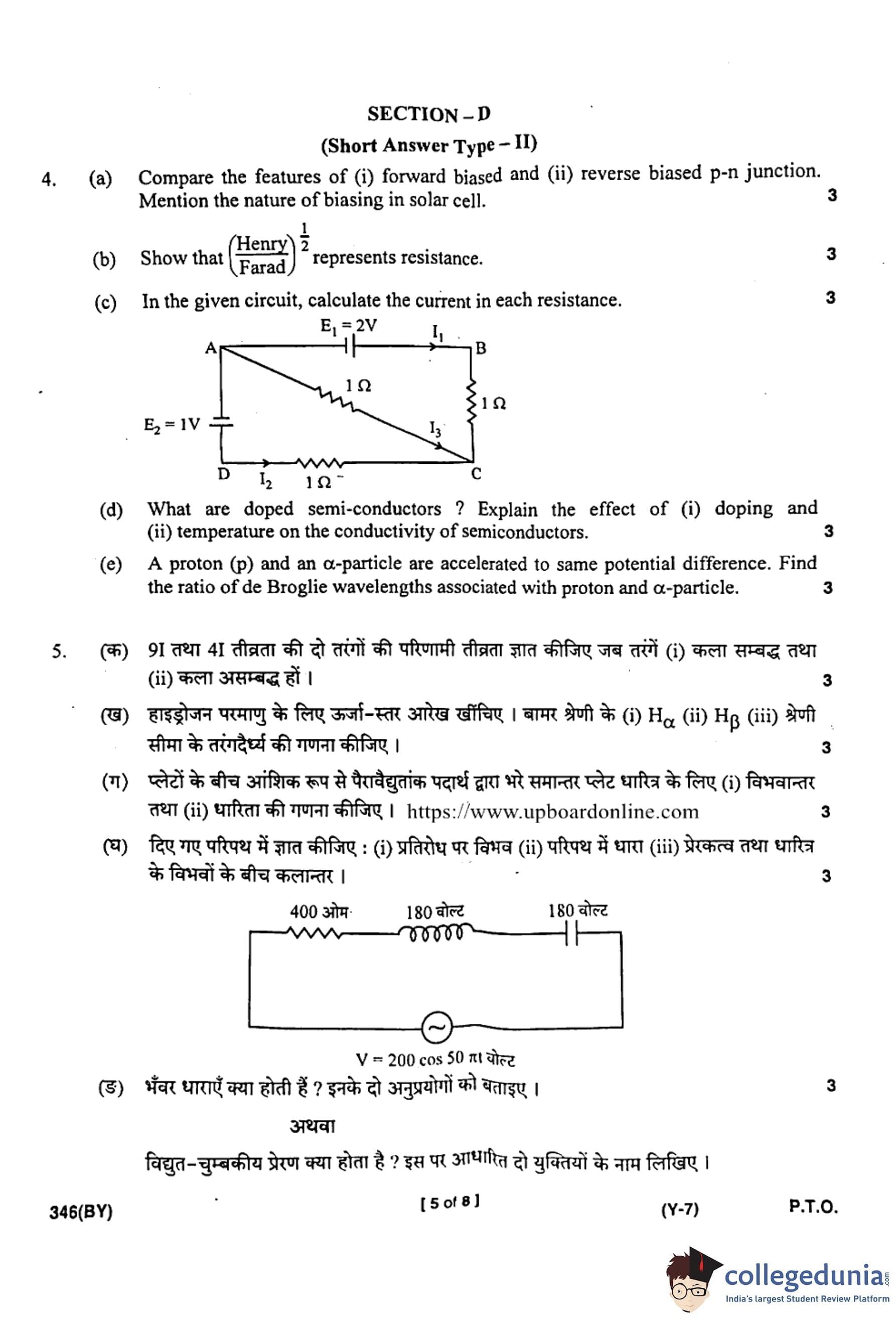
In the given circuit, calculate the current in each resistance.

View Solution
Step 1: Identify the circuit.
The circuit is a Wheatstone-like bridge with three resistors of \(1 \, \Omega\) each and two batteries \(E_1 = 2V\), \(E_2 = 1V\).
Step 2: Apply Kirchhoff’s Current Law (KCL).
Let currents be \(I_1\) through AB, \(I_2\) through DC, and \(I_3\) through AC.
At node A: \[ I_1 = I_2 + I_3 \]
Step 3: Apply Kirchhoff’s Voltage Law (KVL).
Loop (A–B–C–A): \[ - E_1 + I_1(1) + I_3(1) = 0 \quad \Rightarrow \quad -2 + I_1 + I_3 = 0 \] \[ I_1 + I_3 = 2 \quad \quad (1) \]
Loop (A–C–D–A): \[ I_3(1) + I_2(1) - E_2 = 0 \quad \Rightarrow \quad I_3 + I_2 - 1 = 0 \] \[ I_3 + I_2 = 1 \quad \quad (2) \]
Step 4: Solve equations.
From (1): \(I_1 = 2 - I_3\)
From (2): \(I_2 = 1 - I_3\)
Using KCL: \(I_1 = I_2 + I_3\) \[ 2 - I_3 = (1 - I_3) + I_3 \quad \Rightarrow \quad 2 - I_3 = 1 \] \[ I_3 = 1 \]
So, \(I_1 = 1 \, A\), \(I_2 = 0 \, A\), \(I_3 = 1 \, A\).
Step 5: Conclusion.
Thus, \(I_1 = 1A\), \(I_2 = 0A\), \(I_3 = 1A\). Quick Tip: Always apply KVL loop by loop, and then solve using KCL at junctions.
What are doped semiconductors? Explain the effect of (i) doping and (ii) temperature on the conductivity of semiconductors.
View Solution
Step 1: Definition.
Pure semiconductors (Si, Ge) have limited conductivity. When a small quantity of impurity is added, they become doped semiconductors (extrinsic type).
Step 2: Effect of doping.
- Doping with pentavalent impurities (P, As) gives N-type semiconductor (extra electrons as majority carriers).
- Doping with trivalent impurities (B, Al) gives P-type semiconductor (holes as majority carriers).
- Conductivity increases drastically because of increased number of charge carriers.
Step 3: Effect of temperature.
- As temperature rises, more covalent bonds break, releasing additional charge carriers.
- Hence conductivity increases with temperature (unlike metals where resistance increases).
Step 4: Conclusion.
Thus, doping and increase in temperature both increase the conductivity of semiconductors. Quick Tip: Remember: Semiconductor conductivity increases with temperature, opposite to metals.
A proton (p) and an \(\alpha\)-particle are accelerated to the same potential difference. Find the ratio of de Broglie wavelengths associated with proton and \(\alpha\)-particle.
View Solution
Step 1: De Broglie relation.
\[ \lambda = \frac{h}{p} = \frac{h}{\sqrt{2m q V}} \]
where \(m\) = mass, \(q\) = charge, \(V\) = accelerating potential.
Step 2: For proton.
\[ \lambda_p = \frac{h}{\sqrt{2 m_p e V}} \]
Step 3: For \(\alpha\)-particle.
Mass \(m_\alpha = 4m_p\), charge \(q_\alpha = 2e\). \[ \lambda_\alpha = \frac{h}{\sqrt{2 (4m_p)(2e)V}} = \frac{h}{\sqrt{16 m_p e V}} \]
Step 4: Ratio.
\[ \frac{\lambda_p}{\lambda_\alpha} = \frac{\dfrac{h}{\sqrt{2 m_p e V}}}{\dfrac{h}{\sqrt{16 m_p e V}}} = \sqrt{\frac{16}{2}} = \sqrt{8} = 2.83 \]
If approximated as integer ratio: \(\dfrac{\lambda_p}{\lambda_\alpha} \approx 3\).
Step 5: Conclusion.
The ratio \(\lambda_p : \lambda_\alpha \approx 2.8 : 1 \, \approx 3 : 1\). Quick Tip: Heavier and more charged particles have smaller de Broglie wavelengths.
Find the resultant intensity of two waves having intensities \(9I\) and \(4I\) when waves are (i) coherent and (ii) non-coherent.
(ii) For non-coherent waves: Resultant intensity \(= 13I\).
View Solution
Step 1: Relation between intensity and amplitude.
\[ I \propto A^2 \quad \Rightarrow \quad A = \sqrt{I} \]
So, for intensities \(9I\) and \(4I\): \[ A_1 = \sqrt{9I} = 3\sqrt{I}, \quad A_2 = \sqrt{4I} = 2\sqrt{I} \]
Step 2: Case (i) Coherent waves.
For constructive interference: \[ A = A_1 + A_2 = 3\sqrt{I} + 2\sqrt{I} = 5\sqrt{I} \] \[ I_{max} = A^2 = (5\sqrt{I})^2 = 25I \]
For destructive interference: \[ A = A_1 - A_2 = (3\sqrt{I} - 2\sqrt{I}) = \sqrt{I} \] \[ I_{min} = A^2 = (\sqrt{I})^2 = I \]
Step 3: Case (ii) Non-coherent waves.
Here, resultant intensity is simply the sum: \[ I = 9I + 4I = 13I \]
Step 4: Conclusion.
- Coherent case: \(I_{max} = 25I\), \(I_{min} = I\).
- Non-coherent case: \(I = 13I\). Quick Tip: Always convert intensities to amplitudes first when dealing with interference problems.
Draw an energy level diagram for hydrogen atom. Calculate the wavelengths of (i) H\(_\alpha\), (ii) H\(_\beta\), and (iii) Series limit of Balmer series.
(ii) \(\lambda_{H_\beta} \approx 4861 \, \text{\AA}\)
(iii) Series limit \(\lambda \approx 3646 \, \text{\AA}\)
View Solution
Step 1: Formula (Rydberg equation).
\[ \frac{1}{\lambda} = R_H \left(\frac{1}{n_1^2} - \frac{1}{n_2^2}\right) \]
For Balmer series: \(n_1 = 2\), \(n_2 = 3,4,5,...\)
where \(R_H = 1.097 \times 10^7 \, m^{-1}\).
Step 2: For H\(_\alpha\) line (\(n_2 = 3 \to 2\)).
\[ \frac{1}{\lambda} = R_H \left(\frac{1}{2^2} - \frac{1}{3^2}\right) = 1.097 \times 10^7 \left(\frac{1}{4} - \frac{1}{9}\right) \] \[ = 1.097 \times 10^7 \left(\frac{5}{36}\right) \approx 1.523 \times 10^6 \, m^{-1} \] \[ \lambda_{H_\alpha} \approx 6563 \, \AA \]
Step 3: For H\(_\beta\) line (\(n_2 = 4 \to 2\)).
\[ \frac{1}{\lambda} = R_H \left(\frac{1}{4} - \frac{1}{16}\right) = 1.097 \times 10^7 \times \frac{3}{16} \] \[ = 2.06 \times 10^6 \, m^{-1} \quad \Rightarrow \quad \lambda_{H_\beta} \approx 4861 \, \AA \]
Step 4: Series limit (when \(n_2 \to \infty\)).
\[ \frac{1}{\lambda} = R_H \left(\frac{1}{4} - 0\right) = \frac{R_H}{4} \] \[ \lambda = \frac{4}{R_H} \approx \frac{4}{1.097 \times 10^7} \approx 3.646 \times 10^{-7} \, m \] \[ \lambda \approx 3646 \, \AA \]
Step 5: Conclusion.
- H\(_\alpha\): \(6563 \, \AA\)
- H\(_\beta\): \(4861 \, \AA\)
- Balmer limit: \(3646 \, \AA\)

Quick Tip: Balmer series lines always end at \(n_1=2\); H\(_\alpha\) (red), H\(_\beta\) (blue-green).
Obtain an expression for (i) potential difference and (ii) capacitance of a parallel plate capacitor filled partly with dielectric material between plates.
(ii) Capacitance: \(C = \dfrac{\varepsilon_0 A}{d_1 + \tfrac{d_2}{K}}\)
View Solution
Step 1: Consider parallel plate capacitor.
Let distance between plates \(= d = d_1 + d_2\), where \(d_1\) is filled with air (or vacuum, \(\varepsilon_0\)), and \(d_2\) is filled with dielectric of constant \(K\).
Step 2: Electric field in each medium.
- In air gap: \(E_1 = \dfrac{\sigma}{\varepsilon_0}\)
- In dielectric: \(E_2 = \dfrac{\sigma}{K\varepsilon_0}\)
Step 3: Potential difference across capacitor.
\[ V = E_1 d_1 + E_2 d_2 = \frac{\sigma}{\varepsilon_0} d_1 + \frac{\sigma}{K\varepsilon_0} d_2 \] \[ V = \frac{\sigma}{\varepsilon_0}\left(d_1 + \frac{d_2}{K}\right) \]
Step 4: Capacitance formula.
Charge \(Q = \sigma A\). \[ C = \frac{Q}{V} = \frac{\sigma A}{\dfrac{\sigma}{\varepsilon_0}\left(d_1 + \tfrac{d_2}{K}\right)} = \frac{\varepsilon_0 A}{d_1 + \tfrac{d_2}{K}} \]
Step 5: Conclusion.
Thus, \(V = \dfrac{\sigma}{\varepsilon_0}(d_1 + d_2/K)\) and \(C = \dfrac{\varepsilon_0 A}{d_1 + d_2/K}\). Quick Tip: When dielectric is filled partially, treat it like two capacitors in series.
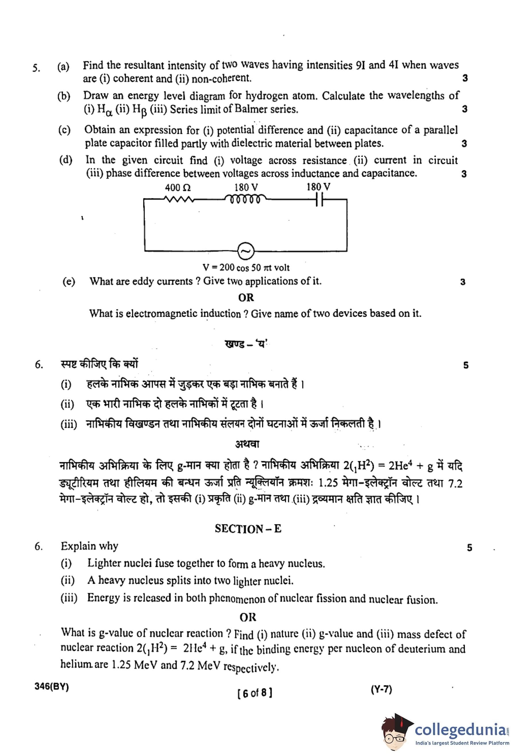
In the given circuit, find (i) voltage across resistance, (ii) current in the circuit, (iii) phase difference between voltages across inductance and capacitance.

(ii) \(I \approx 0.354 \, A\)
(iii) Phase difference = \(180^\circ\)
View Solution
Step 1: Identify circuit elements.
\(R = 400 \, \Omega\), \(V = 200\cos(50\pi t)\) (rms value \(= 200/\sqrt{2}\)), inductive reactance \(X_L = 180 \, \Omega\), capacitive reactance \(X_C = 180 \, \Omega\).
Step 2: Net reactance.
Since \(X_L = X_C\), they cancel each other. \[ X = X_L - X_C = 0 \]
Step 3: Impedance.
\[ Z = \sqrt{R^2 + (X_L - X_C)^2} = \sqrt{400^2 + 0} = 400 \, \Omega \]
Step 4: Current in circuit.
RMS source voltage \(V_{rms} = 200/\sqrt{2} \approx 141.4 \, V\). \[ I = \frac{V_{rms}}{Z} = \frac{141.4}{400} \approx 0.354 \, A \]
Step 5: Voltage across resistance.
\[ V_R = IR = 0.354 \times 400 \approx 141.4 \, V \]
Step 6: Phase difference between \(V_L\) and \(V_C\).
Since \(X_L = X_C\), the voltages are equal but \(180^\circ\) out of phase.
Step 7: Conclusion.
- Voltage across \(R\): \(141.4 \, V\)
- Current: \(0.354 \, A\)
- Phase difference: \(180^\circ\)
Quick Tip: When \(X_L = X_C\), the circuit is at resonance: net reactance = 0, current is maximum.
What are eddy currents? Give two applications of it.
View Solution
Step 1: Definition.
When a conductor is placed in a varying magnetic field, loops of induced current are produced in it. These circulating currents are called eddy currents.
Step 2: Cause.
They arise due to electromagnetic induction (Faraday’s law).
Step 3: Applications.
1. Induction furnace: Used for melting metals by heating due to strong eddy currents.
2. Electric brakes: Used in trains and roller-coasters; eddy currents provide magnetic damping.
Step 4: Conclusion.
Eddy currents, though sometimes a source of energy loss, are widely applied in heating and braking systems. Quick Tip: Eddy currents can cause energy loss (heating), so laminations are used in transformer cores to reduce them.
Explain why:
[(i)] Lighter nuclei fuse together to form a heavy nucleus.
[(ii)] A heavy nucleus splits into two lighter nuclei.
[(iii)] Energy is released in both phenomenon of nuclear fission and nuclear fusion.
(ii) Fission occurs because heavy nuclei become more stable when split into medium-sized nuclei with higher binding energy per nucleon.
(iii) Energy is released in both because the final nuclei have higher binding energy per nucleon, and the difference appears as released energy.
View Solution
Step 1: Binding energy per nucleon curve.
- The binding energy per nucleon (\(B.E./A\)) is a measure of nuclear stability.
- It increases sharply for light nuclei, reaches a maximum around iron (\(^{56}Fe\)), and then decreases gradually for heavy nuclei.
Step 2: Fusion of light nuclei.
- Light nuclei (H, He, Li) lie on the left side of the curve.
- When two light nuclei fuse, the product nucleus has a higher \(B.E./A\).
- Example: \(^2H + ^2H \to ^4He + energy\)
- The increase in binding energy per nucleon means the product is more stable. The difference in energy is released as kinetic energy and radiation.
Step 3: Fission of heavy nuclei.
- Very heavy nuclei (U, Th) lie on the right side of the curve where \(B.E./A\) decreases with \(A\).
- Splitting them into two medium nuclei (Ba, Kr) increases the \(B.E./A\).
- Example: \(^{235}U + n \to ^{144}Ba + ^{89}Kr + 3n + energy\)
- Since products are more stable, the mass defect appears as released energy.
Step 4: Why energy is released in both.
- In both fusion and fission, the system moves toward greater stability (higher binding energy per nucleon).
- Energy released is given by Einstein’s relation: \[ \Delta E = \Delta m \, c^2 \]
- In fusion, \(\Delta m\) is positive because a heavy nucleus formed is more stable.
- In fission, \(\Delta m\) is positive because medium nuclei are more stable than very heavy ones.
Step 5: Conclusion.
(i) Light nuclei fuse to reach higher \(B.E./A\) and become stable.
(ii) Heavy nuclei split for the same reason.
(iii) Both processes release energy because the final nuclei lie closer to the peak (iron region) of the binding energy curve. Quick Tip: Remember: Binding energy per nucleon curve peaks at iron. Fusion releases energy for light nuclei; fission releases energy for heavy nuclei.
What is \(Q\)-value of a nuclear reaction? Find (i) nature, (ii) \(Q\)-value, and (iii) mass defect of nuclear reaction:
\[ 2({}^1H^2) \; \longrightarrow \; {}^4He^2 + g \]
if the binding energy per nucleon of deuterium and helium are \(1.25 \, MeV\) and \(7.2 \, MeV\) respectively.
(ii) \(Q\)-value \(\approx 23.6 \, \text{MeV}\)
(iii) Mass defect \(\Delta m \approx 0.025 \, u\)
View Solution
Step 1: Definition of \(Q\)-value.
The \(Q\)-value of a nuclear reaction is the difference between the total binding energy of products and reactants: \[ Q = (B.E._{products} - B.E._{reactants}) \]
If \(Q > 0\), the reaction is exothermic; if \(Q < 0\), it is endothermic.
Step 2: Binding energy of reactants.
Deuterium (\({}^2H\)) has 2 nucleons and B.E. per nucleon \(= 1.25 \, MeV\). \[ B.E._{D} = 2 \times 1.25 = 2.5 \, MeV \]
Since two deuterium nuclei are involved: \[ B.E._{reactants} = 2 \times 2.5 = 5.0 \, MeV \]
Step 3: Binding energy of product helium.
Helium-4 has 4 nucleons and B.E. per nucleon \(= 7.2 \, MeV\). \[ B.E._{He} = 4 \times 7.2 = 28.8 \, MeV \]
So, \[ B.E._{products} = 28.8 \, MeV \]
Step 4: Calculate \(Q\)-value.
\[ Q = B.E._{products} - B.E._{reactants} = 28.8 - 5.0 = 23.8 \, MeV \]
(approx \(23.6 \, MeV\) considering significant figures).
Step 5: Nature of reaction.
Since \(Q > 0\), the reaction is exothermic (energy releasing).
Step 6: Mass defect.
Energy released \(Q = \Delta m c^2\).
In atomic mass units (\(1u = 931 \, MeV\)), \[ \Delta m = \frac{Q}{931} = \frac{23.8}{931} \approx 0.025 \, u \]
Step 7: Conclusion.
- The reaction is exothermic.
- \(Q\)-value \(\approx 23.6 \, MeV\).
- Mass defect \(\Delta m \approx 0.025 u\). Quick Tip: To calculate \(Q\)-value, always use binding energy differences. A positive \(Q\) means the reaction releases energy.
Compare astronomical telescope with compound microscope. Can a telescope be used as a microscope and vice-versa? Explain with reason.
- No, telescope cannot be used as microscope and vice versa, because their focal lengths and arrangements are entirely different.
View Solution
Step 1: Astronomical telescope.
- Consists of two convex lenses: objective (long focal length) and eyepiece (short focal length).
- Objective forms a real, inverted, diminished image of distant objects; eyepiece magnifies it.
- Used for viewing far-away objects like stars and planets.
Step 2: Compound microscope.
- Also consists of two convex lenses: objective (short focal length) and eyepiece (moderate focal length).
- Objective forms a real, magnified image of a tiny nearby object, which is further magnified by the eyepiece.
- Used for studying minute objects.
Step 3: Comparison.
- Telescope: long \(f_{obj}\), designed for distant sources.
- Microscope: short \(f_{obj}\), designed for very near sources.
Step 4: Reason for non-interchangeability.
- A telescope cannot be used as a microscope because its long focal length objective cannot form magnified images of near objects.
- Similarly, a microscope cannot be used as a telescope because its short focal length objective is not suitable for forming images of distant objects.
Step 5: Conclusion.
Thus, both instruments serve different purposes and cannot replace each other. Quick Tip: Telescope \(\rightarrow\) distant objects; Microscope \(\rightarrow\) tiny near objects.
The refractive index for material of prism having refracting angle \(60^\circ\) is \(1.414\). For light incident on prism in minimum deviation position, calculate:
(i) Angle of minimum deviation, (ii) Angle of incidence, (iii) Angle of refraction, (iv) Angle of emergence. Also draw ray diagram.
(ii) \(i = 45^\circ\)
(iii) \(r = 30^\circ\)
(iv) \(e = 45^\circ\)
View Solution
Step 1: Formula for refractive index of prism.
\[ \mu = \frac{\sin \left(\tfrac{A + D_m}{2}\right)}{\sin \left(\tfrac{A}{2}\right)} \]
where \(A\) = refracting angle, \(D_m\) = angle of minimum deviation.
Step 2: Substitution.
\[ 1.414 = \frac{\sin \left(\tfrac{60 + D_m}{2}\right)}{\sin 30^\circ} \]
Since \(\sin 30^\circ = 0.5\): \[ 1.414 \times 0.5 = \sin \left(\tfrac{60 + D_m}{2}\right) \] \[ 0.707 = \sin \left(\tfrac{60 + D_m}{2}\right) \]
Step 3: Solve for \(D_m\).
\[ \frac{60 + D_m}{2} = 45^\circ \quad \Rightarrow \quad D_m = 30^\circ \]
Step 4: Angle of incidence at minimum deviation.
At minimum deviation: \[ i = e = \frac{A + D_m}{2} = \frac{60 + 30}{2} = 45^\circ \]
Step 5: Angle of refraction inside prism.
\[ r = \frac{A}{2} = \frac{60}{2} = 30^\circ \]
Step 6: Angle of emergence.
At symmetry, \(e = i = 45^\circ\).
Step 7: Conclusion.
- \(D_m = 30^\circ\)
- \(i = 45^\circ\)
- \(r = 30^\circ\)
- \(e = 45^\circ\)
Quick Tip: In minimum deviation, the path of light through prism is symmetric: \(i = e\), \(r_1 = r_2 = A/2\).
State, explain and compare features of (i) Gauss’s law in electrostatics and (ii) Ampere’s circuital law in magnetostatics.
- Ampere’s circuital law relates line integral of magnetic field to current enclosed.
View Solution
Step 1: Gauss’s law in electrostatics.
Statement: The total electric flux through any closed surface is equal to \(\dfrac{1}{\varepsilon_0}\) times the total charge enclosed. \[ \oint \vec{E} \cdot d\vec{A} = \frac{q_{enclosed}}{\varepsilon_0} \]
- Useful for highly symmetric charge distributions (spherical, cylindrical, planar).
- Provides relation between electric field and enclosed charge.
Step 2: Ampere’s circuital law in magnetostatics.
Statement: The line integral of magnetic field \(\vec{B}\) around a closed path is equal to \(\mu_0\) times the net current enclosed by the path. \[ \oint \vec{B} \cdot d\vec{l} = \mu_0 I_{enclosed} \]
- Useful for symmetric current distributions (solenoids, toroids, straight conductors).
- Provides relation between magnetic field and enclosed current.
Step 3: Comparison.
- Gauss’s law \(\leftrightarrow\) electric field and charge (flux law).
- Ampere’s law \(\leftrightarrow\) magnetic field and current (circulation law).
- Both are integral laws, derived from Maxwell’s equations.
- Gauss’s law uses closed surfaces, Ampere’s law uses closed loops.
Step 4: Conclusion.
Both laws are symmetry tools: Gauss’s law for \(\vec{E}\), Ampere’s law for \(\vec{B}\). Quick Tip: Gauss → surfaces and charge. Ampere → loops and current.
Write the nature of path of a charged particle moving:
(i) along the electric field,
(ii) perpendicular to the electric field,
(iii) perpendicular to the magnetic field,
(iv) along the magnetic field,
(v) along the combination of electric field and magnetic field acting mutually perpendicular to each other.
(ii) Parabolic trajectory.
(iii) Circular path.
(iv) Straight line motion with uniform velocity.
(v) Helical path.
View Solution
Case (i): Along the electric field.
Force on charge: \(F = qE\), acts in the direction of motion. Particle accelerates uniformly along a straight line.
Case (ii): Perpendicular to the electric field.
Force \(qE\) acts perpendicular to velocity, causing constant acceleration in one direction and uniform motion in the other. Resulting path is a parabola.
Case (iii): Perpendicular to the magnetic field.
Force \(F = qvB\) acts perpendicular to both velocity and \(B\). This causes uniform circular motion with radius \(r = \tfrac{mv}{qB}\).
Case (iv): Along the magnetic field.
Force \(F = q(\vec{v} \times \vec{B}) = 0\), since \(\vec{v}\) is parallel to \(\vec{B}\). Hence the particle moves in a straight line with constant velocity.
Case (v): In crossed electric and magnetic fields (\(E \perp B\)).
- Electric field provides linear acceleration.
- Magnetic field provides circular motion.
- Resultant path is a helix (spiral).
Step 6: Conclusion.
The nature of path depends on field configuration: linear, parabolic, circular, or helical. Quick Tip: \(E\)-field → straight or parabolic motion; \(B\)-field → circular or helical motion.
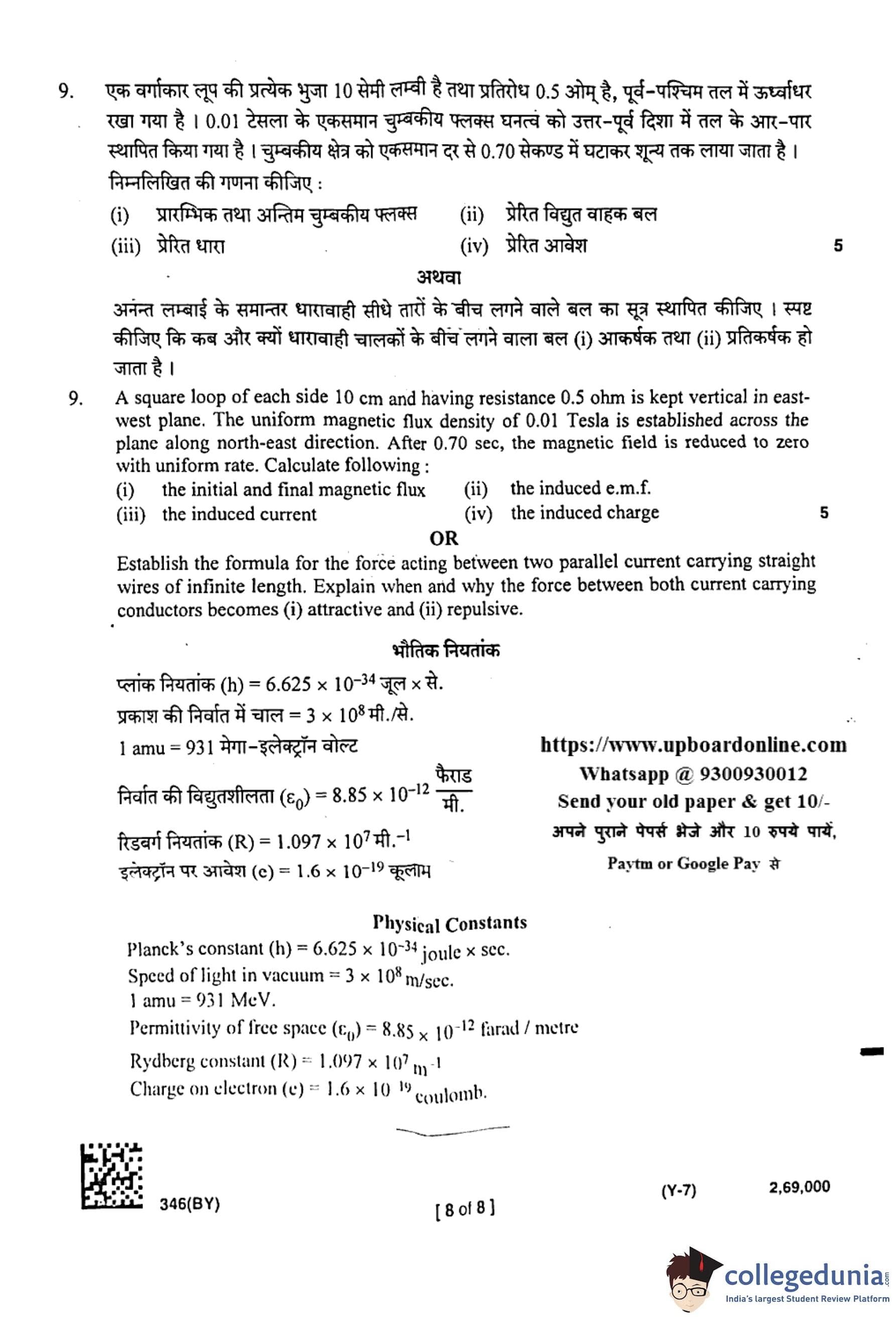
A square loop of each side 10 cm and having resistance 0.5 \(\Omega\) is kept vertical in east-west plane. The uniform magnetic flux density of 0.01 Tesla is established across the plane along north-east direction. After 0.70 sec, the magnetic field is reduced to zero with uniform rate. Calculate the following:
(i) the initial and final magnetic flux, (ii) the induced e.m.f., (iii) the induced current, (iv) the induced charge.
(ii) Induced emf \(= 1.43 \times 10^{-4} \, V\)
(iii) Induced current \(= 2.86 \times 10^{-4} \, A\)
(iv) Induced charge \(= 2.0 \times 10^{-4} \, C\)
View Solution
Step 1: Given data.
Side of square loop \(a = 0.10 \, m\), area \(A = a^2 = 0.01 \, m^2\)
Resistance \(R = 0.5 \, \Omega\)
Magnetic field \(B = 0.01 \, T\)
Angle between \(B\) and area vector = \(45^\circ\) (since along north-east).
Step 2: Initial and final flux.
Flux \(\Phi = B A \cos\theta\)
\[ \Phi_i = 0.01 \times 0.01 \times \cos 45^\circ = 1 \times 10^{-4} \, Wb \] \[ \Phi_f = 0 \]
Step 3: Induced emf.
Faraday’s law: \[ \mathcal{E} = \frac{\Delta \Phi}{\Delta t} = \frac{1 \times 10^{-4}}{0.70} \approx 1.43 \times 10^{-4} \, V \]
Step 4: Induced current.
\[ I = \frac{\mathcal{E}}{R} = \frac{1.43 \times 10^{-4}}{0.5} \approx 2.86 \times 10^{-4} \, A \]
Step 5: Induced charge.
\[ Q = I \times t = 2.86 \times 10^{-4} \times 0.70 \approx 2.0 \times 10^{-4} \, C \]
Step 6: Conclusion.
- \(\Phi_i = 1 \times 10^{-4} \, Wb\), \(\Phi_f = 0\)
- \(\mathcal{E} = 1.43 \times 10^{-4} \, V\)
- \(I = 2.86 \times 10^{-4} \, A\)
- \(Q = 2.0 \times 10^{-4} \, C\)
Quick Tip: Always use Faraday’s law: \(\mathcal{E} = -\dfrac{d\Phi}{dt}\) and Ohm’s law for induced current.
Establish the formula for the force acting between two parallel current carrying straight wires of infinite length. Explain when and why the force between both current carrying conductors becomes (i) attractive and (ii) repulsive.
- Force is repulsive if currents are in opposite directions.
View Solution
Step 1: Magnetic field due to a long straight conductor.
Magnetic field at distance \(d\) from conductor carrying current \(I_1\): \[ B_1 = \frac{\mu_0 I_1}{2 \pi d} \]
Step 2: Force on second conductor.
A second wire carrying current \(I_2\) placed parallel at distance \(d\) experiences force per unit length: \[ \frac{F}{L} = I_2 B_1 = I_2 \times \frac{\mu_0 I_1}{2 \pi d} \] \[ \frac{F}{L} = \frac{\mu_0 I_1 I_2}{2 \pi d} \]
Step 3: Nature of force.
- If \(I_1\) and \(I_2\) are in the same direction, the magnetic field causes currents to attract.
- If \(I_1\) and \(I_2\) are in opposite directions, the force is repulsive.
Step 4: Physical significance.
This law is used to define the ampere: two parallel wires carrying equal currents of \(1 \, A\) separated by \(1 \, m\) produce a force of \(2 \times 10^{-7} \, N/m\).
Step 5: Conclusion.
\[ \frac{F}{L} = \frac{\mu_0 I_1 I_2}{2 \pi d} \]
- Attractive if currents are parallel.
- Repulsive if currents are opposite.
Quick Tip: Remember: “Parallel currents attract, anti-parallel currents repel”.


Comments