Biology Strategist, 14 Yrs | Updated on - Jun 29, 2026
The NCERT Solutions for Class 10 Science Chapter 11 Electricity solve all 41 questions (23 in-text and 18 end-of-chapter exercises) for the latest 2026-27 CBSE syllabus.
Every answer follows the textbook flow: electric current and circuit, potential difference, Ohm's law, resistance and resistivity, resistors in series and parallel, the heating effect of current and electric power.
All 41 NCERT questions solved with full step-by-step working, formula then substitution then arithmetic, and an Expert Solution per question for board-exam strategy.
Complete coverage of electric current, Ohm's law, resistance, series and parallel circuits, Joule's law of heating and electric power as tested in the CBSE Class 10 board paper.
Answers written in plain English for the 2026-27 CBSE syllabus, useful for the board exam and school unit tests.
Solved by Collegedunia Science Experts
These NCERT Solutions for Class 10 Science Chapter 11 Electricity are checked against the latest 2026-27 NCERT textbook and refined against the last five years of CBSE board papers. Each of the 41 questions gives a Check Solution for the clean board answer and an Expert Solution for extra marks.
What the NCERT Solutions for Class 10 Science Chapter 11 Electricity Cover
This chapter answers one big question: what is electric current, and how does it flow through a circuit? These solutions follow the NCERT order while filling the gaps students hit in the exam.
Electric current and circuit: current is the rate of flow of charge, I = Q/t, and it flows only in a closed conducting loop.
Potential difference and Ohm's law: V = W/Q gives energy per unit charge, and Ohm's law V = IR ties voltage, current and resistance together.
Resistance and resistivity: R = ρl/A shows resistance grows with length, falls with area, and depends on the material.
Series, parallel, heating and power: how resistors combine, Joule's law H = I²Rt, and the three forms of power P = VI = I²R = V²/R.
Question Breakdown by Section of the Electricity Chapter NCERT Solutions
Chapter 11 carries 41 questions in total: 23 in-text and 18 end-of-chapter exercises. The table maps each section to its topic and the answer style the CBSE board rewards.
Section
Topic covered
Question type
Typical marks
11.1 to 11.2
Electric circuit, current, charge and potential difference
Definitions and one-line numericals
1 to 2 marks
11.5
Ohm's law, resistance and resistivity factors
Reasoning plus short numericals
2 to 3 marks
11.6
Resistors in series and parallel
Circuit design and equivalent resistance
3 marks
11.7
Heating effect of current (Joule's law)
H = I²Rt numericals
2 to 3 marks
11.8
Electric power and energy
P = VI numericals, kWh
3 marks
Exercises
Mixed MCQ, reasoning and full numericals
One-mark MCQ to five-mark long answer
1 to 5 marks
The series and parallel numericals and the power and heating sums carry the heaviest marks. Students who show the formula, the substitution and the arithmetic on separate lines score full marks.
Electric Current, Potential Difference and Ohm's Law
Electric current is the rate of flow of electric charge, I = Q/t, measured in amperes. One ampere is one coulomb of charge passing a point every second. Current flows only in a closed circuit, an unbroken conducting loop of a cell, wires, a switch and a device.
Charge is quantised: it comes in whole multiples of the electron charge, e = 1.6 × 10−¹⁹ C, so one coulomb holds 6.25 × 10¹⁸ electrons.
Potential difference V = W/Q is the work done to move one coulomb between two points; its unit, the volt, is one joule per coulomb.
Ohm's law: at constant temperature, V = IR. The graph of V against I is a straight line through the origin whose slope is the resistance.
Quick Tip: Define every unit from its formula. Set the other two quantities to one: in I = Q/t, putting Q = 1 C and t = 1 s gives 1 A = 1 C s−¹; in V = W/Q, putting W = 1 J and Q = 1 C gives 1 V = 1 J C−¹.
The most common one-mark trap is confusing current with voltage. Current counts how much charge moves per second; voltage measures how much energy each coulomb carries.
Resistance, Resistivity and the Factors That Change Them
Resistance is the opposition a conductor offers to current. For a uniform wire at a fixed temperature, R = ρl/A, where l is the length, A the area of cross-section and ρ the resistivity of the material. Resistance is measured in ohms (Ω).
Factor
How it affects R
Why
Length (l)
R increases with l (directly proportional)
A longer wire makes charges push through more material
Area (A)
R decreases as A increases (inversely proportional)
A thicker wire gives charges more room to flow
Material (ρ)
Higher resistivity means higher R
Copper conducts well; nichrome resists about 60 times more
Temperature
R rises as temperature rises
Hotter atoms vibrate more and scatter the electrons
This single relation explains many everyday choices: thick copper cables carry heavy household currents because a large area means low resistance, while a long, thin nichrome coil has high resistance so it heats up. A material is a better conductor when its resistivity is lower, so silver is the best conductor in the NCERT table and copper is a very close second.
Remember: Resistance depends on the wire's size, resistivity does not. Resistivity is the fair, size-free way to compare materials, so always quote resistivity (not resistance) when ranking conductors.
Resistors in Series and Parallel
The two ways to combine resistors behave very differently, and most numerical marks in this chapter come from telling them apart. In series there is one path, so the same current flows through every resistor and the resistances add. In parallel there are many paths, so every branch gets the same voltage and the reciprocals add.
Series: Rs = R₁ + R₂ + R₃. The total resistance is larger than any single resistor, and the supply voltage shares out among them.
Parallel: 1/Rp = 1/R₁ + 1/R₂ + 1/R₃. The total resistance is smaller than the smallest branch, and the branch currents add up to the line current.
To design a target resistance, compare it with a single resistor. A target above one resistor needs a series step; a target below the smallest resistor needs a parallel step. For example, three 6 Ω resistors give 9 Ω as (6 ∥ 6) + 6, and 4 Ω as (6 + 6) ∥ 6. Homes are always wired in parallel so each appliance gets the full 220 V and one device failing does not switch off the rest.
Watch Out: An ammeter goes in series (it carries the current) and a voltmeter goes in parallel across the component (it has very high resistance). Swapping them either shorts the circuit or reads zero.
Heating Effect of Current and Electric Power
When current passes through a resistor, electrical energy turns into heat. Joule's law of heating says H = I²Rt: the heat is proportional to the square of the current, the resistance and the time. This is the idea behind every heater, toaster, iron and fuse.
Same current, more heat in higher R: a heater's cord and its element carry the same current, but the high-resistance nichrome element glows while the low-resistance copper cord stays cool.
Electric power is the rate of using energy: P = VI, and using Ohm's law also P = I²R = V²/R. Pick the form whose quantities you already know.
Commercial energy unit is the kilowatt-hour: 1 kWh = 3.6 × 10⁶ J. Keep power in kW and time in hours to read energy straight in kWh.
A frequent exam trap is the difference between rate of heat (power, in watts) and total heat (energy, in joules). "Rate" already means per second, so for the rate you stop at P = I²R and never multiply by the time. Another trap is power scaling: for a fixed resistance P ∝ V², so a 220 V, 100 W bulb run at 110 V uses only 25 W, one-quarter of its rating.
Quantity
Formula
SI unit
Heat produced
H = I²Rt
joule (J)
Electric power
P = VI = I²R = V²/R
watt (W)
Electrical energy
W = Pt = VIt
joule (J) or kWh
Common Mistakes Students Make in the Electricity Chapter
The repeat-offender mistakes in Electricity board answers:
Forgetting to square the current: in H = I²Rt and P = I²R, compute I² first. Skipping the square turns a correct method into a wrong number.
Skipping unit conversions: 2.5 mA is 2.5 × 10−³ A and 0.5 mm is 5 × 10−⁴ m. Forgetting the prefix throws the answer off by a factor of a thousand.
Mixing up series and parallel: add resistances in series, add reciprocals in parallel. The parallel total is always below the smallest branch.
Confusing rate of heat with total heat: rate is power (watts); total heat is power times time (joules). Read the wording carefully.
Wrong meter connection: ammeter in series, voltmeter in parallel. Reversing them gives a wrong or zero reading.
How to Use the Electricity NCERT Solutions PDF for Board Prep
The Electricity chapter is numerical-heavy, so the best approach is two passes: one for the definitions and formulas, one for working the numericals by hand.
First pass: concepts and formulas (1.5 hours)
Read the chapter and write the eight key relations: I = Q/t, V = W/Q, V = IR, R = ρl/A, the series and parallel rules, H = I²Rt and the three power forms. Add one line of meaning next to each so the formula sticks before you start solving.
Second pass: solve the numericals (3 to 4 hours)
Work the series, parallel, heating and power numericals on paper first, writing formula then substitution then arithmetic on separate lines. Then open these solutions and check each step. Pay attention to squaring the current and to unit conversions, because those two specifics decide full marks.
Board exam angle
For the CBSE board, the most repeated questions are series and parallel equivalent resistance, the heating effect H = I²Rt, and power and energy in kWh. Practising the worked numericals here builds the speed and accuracy the three-mark and five-mark questions need.
Other Resources for Class 10 Science Chapter 11 Electricity
Pair this NCERT Solutions PDF with the matching revision notes, formula sheet, handwritten notes and the official NCERT book chapter. All resources for Class 10 Science Chapter 11 Electricity are linked below.
Resource
What it covers
Open
NCERT Solutions
Step-by-step answers to all 41 questions, with an Expert Solution for each.
You are here
Notes
Concept-first revision notes on current, Ohm's law, resistance, series and parallel circuits, heating and power.
71% of Class 10 students said the hardest part of Electricity was the series and parallel resistor numericals. 3 out of 5 students told us they lost marks by forgetting to square the current in H = I²Rt or by mixing up the series and parallel formulas.
Toppers found that writing the formula, then the substitution, then the arithmetic on separate lines added 1 to 2 marks on every numerical, and the average student spent 5 to 6 hours on this chapter across the first read and exercise practice.
Source: 2026-27 Class 10 Science student poll. Sample of 10,600 students from CBSE schools across 13 states, conducted before the 2026 boards.
NCERT Solutions for Class 10 Science: All Chapters
Related Links: Use the table below to open the NCERT Solutions for the other chapters of Class 10 Science. Every chapter ships with the same step-by-step answer style, full PDF download, and revision FAQ.
All NCERT Solutions for Class 10 Science Chapter 11 Electricity with Step-by-Step Solutions
Tap Check Solution for the clean board answer and Expert Solution for the extra-mark strategy on each of the 41 questions below.
Q 1
What does an electric circuit mean?
Concept used. An electric circuit is a continuous
and closed conducting path along which electric current can flow. It
is built from a source of current (a cell or battery), connecting
wires, a switch (plug key) and one or more devices that use the
current, such as a bulb or a resistor.
Charges flow only when there is a complete path from one
terminal of the cell, through the wires and devices, and back
to the other terminal.
If the path is broken anywhere, for example by opening the
switch, the current stops at once. We then say the circuit is
open.
When the path is unbroken and current flows, the circuit is
said to be closed.
Answer: An electric circuit is a continuous, closed conducting path through which an electric current flows from one terminal of the cell, through the devices, and back to the other terminal.
Recall: A closed circuit has an unbroken path, so current flows. An
open circuit has a gap (switch off, wire cut), so no current
flows. A switch simply makes or breaks this path on demand.
AS
Aarav Sharma
M.Sc Physics, IIT Kanpur
Verified Expert
Picture-first reading. Think of the circuit as a closed loop
that water could run around. Just as water needs an unbroken pipe loop
and a pump to keep flowing, charge needs an unbroken wire loop and a
cell to keep moving. The cell is the pump; the wires are the pipes;
the bulb is the place where the moving charge does useful work.
The key word in the definition is closed. A single battery and
a bulb sitting on a table are not a circuit until you join them with
wires into a loop. The moment the loop is complete, charges drift
steadily and the bulb glows. Break the loop at any point and the bulb
goes dark instantly, even though the cell is still full of energy. In a
board answer always name the four parts (source, connecting wires,
switch and device) and use the words continuous and
closed; those two adjectives carry the marks.
Common board phrasing. CBSE often pairs this with a circuit
diagram. If asked, draw a cell, an ammeter in series, a bulb and a
plug key, all joined into one loop, with the conventional current
shown leaving the positive terminal.
Answer: A closed, continuous conducting loop (source + wires + switch + device) along which current can flow.
Q 2
Define the unit of current.
Concept used.Electric current is the rate of flow
of electric charge through a conductor. If a charge Q flows through
any cross-section of a conductor in time t, the current is
I = Q/t.
The SI unit of charge is the coulomb (C) and the SI unit of time is
the second (s), so the SI unit of current, the ampere (A), is defined
from this equation.
Start from the definition I = Q/t.
Put Q = 1 coulomb and t = 1 second.
Then I = (1 C)/(1 s) = 1 ampere.
So one ampere is the current flowing in a conductor when one
coulomb of charge passes through any cross-section of it in one second:
1 A = 1 C s-1.
Answer: One ampere is the current when 1 coulomb of charge flows through a conductor in 1 second, i.e. 1 A = 1 C s-1.
Quick Tip: Whenever a unit is asked, write the defining equation
(I = Q/t) and substitute the unit values. “1 A = 1 C s-1”
in symbols earns the mark even if your sentence is short.
PI
Priya Iyer
M.Sc Physics, IISc Bangalore
Verified Expert
Strategic angle. A unit is always defined by setting every
other quantity in its defining equation to one. Here the defining
equation is I = Q/t, so put Q = 1 C and t = 1 s and read off
I = 1 A. This same trick defines the volt later (set W = 1 J,
Q = 1 C) and the ohm (set V = 1 V, I = 1 A).
The ampere is one of the seven base SI units, named after the French
physicist André-Marie Ampère. It is worth remembering the size of
a coulomb in everyday terms: one coulomb is the charge of about
6.25 × 10¹⁸ electrons. So a one-ampere current means roughly
six billion billion electrons sweeping past a point each second, which
is why even a small torch bulb carries an enormous number of charge
carriers. A board answer that gives the equation, the substitution and
the symbol form 1 A =1 C s-1 is complete.
Answer: 1 ampere = 1 coulomb per second (1 A=1 C s-1).
Q 3
Calculate the number of electrons constituting one coulomb of charge.
Concept used. Charge is quantised: it comes only in
whole-number multiples of the charge on one electron,
e = 1.6 × 10⁻¹⁹ C. If n electrons together carry a total
charge Q, then
Q = n e ⇒ n = Q/e.
Write the relation.
n = Q/e.
Substitute Q = 1 C and e = 1.6 × 10⁻¹⁹ C.
n = 1/(1.6 × 10-19).
Do the arithmetic.
n = 6.25 × 10¹⁸ electrons.
Answer: One coulomb of charge is made up of n = 6.25 × 10¹⁸ electrons.
Quick Tip: Keep e = 1.6 × 10⁻¹⁹ C ready; dividing 1 by it gives
6.25 × 10¹⁸. The reciprocal 1/1.6 = 0.625 shifts the power
of ten by one, which is the only arithmetic step that trips students up.
KJ
Krishna Joshi
M.Sc Physics, IIT Bombay
Verified Expert
Strategic angle. This is a one-line application of charge
quantisation Q = ne. Solve for the count n = Q/e and substitute.
The whole problem is the single division 1 ÷ (1.6 × 10⁻¹⁹).
The result, 6.25 × 10¹⁸, is worth committing to memory
because it is the bridge between the everyday unit (coulomb) and the
microscopic unit (electron charge). It tells you that the coulomb is a
huge amount of charge on the atomic scale. To handle the power of ten
cleanly, write 1/1.6 = 0.625 first, then move the negative exponent
across: 0.625 × 1019 = 6.25 × 10¹⁸. Students who try
to divide the powers of ten in their head usually slip by a factor of
ten here, so always separate the mantissa from the exponent. The same
relation Q = ne also lets you reverse the question: given a charge,
the number of electrons is fixed because charge cannot take fractional
values of e.
Answer: n = 6.25 × 10¹⁸ electrons per coulomb.
Q 4
Name a device that helps to maintain a potential difference across a conductor.
Concept used. A steady current needs a steady
potential difference across the conductor. A device that can
keep up this potential difference by spending its stored energy is a
cell (or a battery, which is two or more cells
joined together).
Current keeps flowing only while a potential difference is
maintained across the ends of the conductor.
A cell uses the chemical energy stored inside it to keep its
two terminals at different potentials.
Joining several cells gives a battery, which maintains the same
potential difference for longer or at a higher value.
Answer: A cell (or a battery of cells) maintains the potential difference across a conductor.
Why It Matters: A cell does not create charge; it pushes existing charge around the
loop. The chemical reaction inside the cell is what keeps one terminal
positive and the other negative, so the cell slowly runs down as it
keeps the current going.
AM
Aanya Mehta
M.Sc Physics, IIT Delhi
Verified Expert
Quick reading. The single word the examiner wants is
cell (or battery). But understanding why a cell is the right
answer is what protects the mark in a tricky multiple-choice version.
A potential difference is like a height difference for water: water
keeps flowing down a slope only if something keeps lifting it back up.
In a circuit the cell is that lift. Its chemical reaction does work to
separate charge, holding one terminal at a higher potential than the
other even when no current is drawn. Connect a wire and that stored
potential difference drives the charges around. A generator or a
dynamo does the same job using mechanical energy instead of chemical
energy, so in a board answer “a cell, a battery or a generator” is
acceptable, but the cell is the standard textbook answer. The key idea
is that the device must keep spending energy to hold the
terminals apart in potential; a charged object with no energy source
cannot maintain a steady current.
Answer: A cell or battery (also a generator) maintains the potential difference.
Q 5
What is meant by saying that the potential difference between two points is 1 V?
Concept used. The potential difference between two
points is the work done to move a unit positive charge from one point
to the other:
V = W/Q.
Its SI unit, the volt (V), is defined from this relation by setting the
work and the charge each to one unit.
Start from V = W/Q.
Put W = 1 joule and Q = 1 coulomb.
Then V = (1 J)/(1 C) = 1 volt.
So a potential difference of 1 V between two points means that
1 joule of work is done in moving a charge of 1 coulomb from one
point to the other: 1 V = 1 J C-1.
Answer: 1 V means 1 J of work is done to move 1 C of charge between the two points, i.e. 1 V = 1 J C-1.
Quick Tip: The cleanest one-line definition for the board is
“1 V = 1 J C-1”. Always tie the volt back to
energy per unit charge, not to current.
TB
Tara Banerjee
M.Sc Physics, IISc Bangalore
Verified Expert
Strategic angle. Define the unit by setting both other
quantities in V = W/Q to one. With W = 1 J and Q = 1 C you read
off 1 V directly, exactly as the ampere came from I = Q/t.
The deeper meaning is that voltage measures energy per unit
charge. A 1.5 V cell does 1.5 joules of work on every coulomb of
charge that passes through the circuit. This is why a higher-voltage
source can push the same charge harder and deliver more energy. Note
the contrast with current: current counts how much charge moves
per second, while voltage measures how much energy each unit of
charge carries. Mixing the two is the most common error here, so anchor
your answer on the phrase “work done per unit charge”. In symbols,
1 V =1 J C-1, and that compact form is what a marker looks for.
Answer: 1 V is the potential difference when 1 J of work moves 1 C of charge (1 V = 1 J C-1).
Q 6
How much energy is given to each coulomb of charge passing through a 6 V battery?
Concept used. The potential difference of a battery is the
energy it gives to each unit of charge:
V = W/Q ⇒ W = VQ.
Here “each coulomb” means Q = 1 C, and the battery voltage is
V = 6 V.
Write the relation between energy, voltage and charge.
W = VQ.
Substitute V = 6 V and Q = 1 C.
W = 6 V × 1 C.
Do the arithmetic.
W = 6 J.
Answer: Energy given to each coulomb of charge = 6 J.
Recall: A 6 V battery hands 6 J to every coulomb. Double the voltage and each
coulomb carries double the energy; the charge is unchanged.
RV
Rohit Verma
M.Sc Physics, IIT Madras
Verified Expert
Quick reading. The number 6 in “6 V” already is the
energy in joules given to each coulomb, because the volt is defined as
joule per coulomb. So the answer is 6 J with almost no calculation.
The reason this works is the definition V = W/Q. Rearranged it gives
W = VQ, and for one coulomb (Q = 1) the work equals the voltage in
numerical value. This is a useful sanity check throughout the chapter:
the voltage rating of any source tells you, at a glance, the energy per
coulomb it supplies. For a 6 V battery driving a current, every coulomb
that completes the loop receives 6 J from the chemical store and then
delivers that 6 J to the devices in the circuit. Energy is conserved,
so the energy the battery gives out equals the energy the resistors and
bulbs use up. Tie your answer to W = VQ and state the unit (joule)
clearly.
Answer: W = VQ = 6 × 1 = 6 J per coulomb.
Q 7
On what factors does the resistance of a conductor depend?
Concept used. The resistance R of a conductor is
the opposition it offers to the flow of charge. Experiments show that
for a uniform conductor at a fixed temperature,
R = ρ l/A,
where l is its length, A its area of cross-section and ρ the
resistivity, a property of the material.
Length (l). Resistance is directly proportional to
length: a longer wire has more resistance because charges must
push through more material.
Area of cross-section (A). Resistance is inversely
proportional to the area: a thicker wire offers more room, so
it has less resistance.
Nature of the material (ρ). Different materials
have different resistivity; copper has low resistivity (good
conductor) while nichrome has high resistivity.
Temperature. For most conductors, resistance rises as
temperature rises.
Answer: Resistance depends on the length (∝ l), the area of cross-section (∝ 1/A), the nature of the material (ρ), and the temperature of the conductor.
Quick Tip: For full marks list length, area, material (resistivity) and
temperature, and quote R = ρ l / A. Many students forget
temperature; including it shows complete understanding.
AR
Ananya Reddy
M.Sc Physics, IIT Kanpur
Verified Expert
Structural angle. Sort the factors into two groups:
geometry (the size and shape of the wire, captured by l and
A) and material (captured by the resistivity ρ, with
temperature shifting ρ). The single equation R = ρ l / A
holds all three of the first kind in one place.
The geometric dependence is easy to feel physically. A long, thin wire
is like a long, narrow corridor: charges bump along it with difficulty,
so resistance is high. A short, fat wire is a wide, short hallway, so
charges pass easily and resistance is low. That is why thick copper
cables are used to carry heavy household currents. The material factor
is separate: even with identical length and area, a nichrome wire
resists far more than a copper wire because nichrome's resistivity is
about sixty times larger. Temperature acts through the material: as a
metal heats up, its atoms vibrate more and scatter the moving
electrons, raising the resistance. So the complete answer names l,
A, ρ (material) and temperature, with the relation
R = ρ l / A tying the geometric factors together.
Answer: R depends on l (directly), A (inversely), the material's resistivity ρ, and temperature; R = ρ l/A.
Q 8
Will current flow more easily through a thick wire or a thin wire of the same material, when connected to the same source? Why?
Concept used. For the same material and length, resistance
depends on the area of cross-section through
R = ρ l/A,
so resistance is inversely proportional to area A. By Ohm's law
I = V/R, a smaller resistance at the same voltage gives a larger
current.
A thick wire has a larger area of cross-section A than a thin
wire of the same material and length.
Since R ∝ 1/A, the thick wire has a smaller
resistance.
At the same source voltage V, Ohm's law I = V/R then gives
a larger current through the thick wire.
Answer: Current flows more easily through the thick wire, because its larger area of cross-section gives it a smaller resistance (R ∝ 1/A), and a smaller resistance means a larger current at the same voltage.
Recall: Thicker wire ⇒ larger A ⇒ smaller
R = ρ l/A ⇒ larger I = V/R. The chain of three steps
is the whole answer.
VP
Vivaan Patel
M.Sc Physics, IIT Delhi
Verified Expert
Quick reading. Same material, same length, so only the
thickness changes. Thickness sets the area A, and R ∝ 1/A,
so thicker means less resistance and therefore more current.
A helpful picture is water flowing through pipes. A wide pipe lets more
water through per second than a narrow one for the same pump pressure,
because there is simply more room for flow. A thick wire is the wide
pipe for charge. Doubling the radius of a wire multiplies its area by
four (since area depends on radius squared), so the resistance falls to
one-quarter and the current rises four times. This is exactly why
appliances that draw heavy currents, such as a geyser or an air
conditioner, are wired with thick copper cables, while a low-current
device like a phone charger uses thin wire. Always justify the answer
with R = ρ l/A and then Ohm's law; stating the conclusion without
the reason loses half the marks.
Answer: Thick wire: larger A gives smaller R, so a larger current flows.
Q 9
Let the resistance of an electrical component remains constant while the potential difference across the two ends of the component decreases to half of its former value. What change will occur in the current through it?
Concept used. For a component of constant resistance, Ohm's
law V = IR tells us that current is directly proportional to the
potential difference:
I = V/R (R constant) ⇒ I ∝ V.
If the voltage is halved, the current is halved.
Let the original current be I1 = V/R.
The new voltage is half the old one: V2 = V/2.
The new current is
I2 = V2/R = (V/2)/R = 1/2·V/R = I1/2.
Answer: The current also reduces to half of its former value, because at constant resistance I ∝ V.
Quick Tip: When R is fixed, current tracks voltage exactly: halve V and I
halves; double V and I doubles. The ratio V/I stays equal to R.
AN
Aditya Nair
M.Sc Physics, IIT Madras
Verified Expert
Strategic angle. Treat resistance as the fixed conversion
factor between voltage and current. With R held constant, I = V/R
is a straight proportionality, so whatever you do to V happens to I.
The cleanest way to answer “what happens” questions is to take the
ratio of the new case to the old case so the unknown R cancels:
I2/I1 = (V2/R)/(V1/R) = V2/V1 = 1/2.
This shows I2 = I1/2 without ever needing the numerical values of
V or R. The ratio method is a powerful habit for the whole
chapter: it works for any “if this is halved/doubled” problem and
avoids carrying unknown constants. Physically, the result makes sense
because the resistor obeys Ohm's law, so its V versus I graph is a
straight line through the origin; moving to half the voltage simply
slides you halfway down that line to half the current.
Answer: Current becomes half; I2/I1 = V2/V1 = 1/2.
Q 10
Why are coils of electric toasters and electric irons made of an alloy rather than a pure metal?
Concept used. Heating appliances rely on the
heating effect of current, H = I2 R t. The coil must get
hot enough to glow and must survive that heat in air for a long time.
Alloys are chosen because of two properties they have that
pure metals lack.
Higher resistivity. The resistivity of an alloy is
generally much higher than that of its constituent pure
metals, so for the same size the coil has more resistance and
produces more heat (H = I2 R t).
High melting point. Alloys such as nichrome have a
high melting point, so the coil can reach a red-hot glowing
temperature without melting.
Do not oxidise easily. Alloys do not burn or oxidise
readily even when red hot in air, so the coil lasts long
instead of crumbling.
Answer: Alloys (like nichrome) are used because they have a high resistivity, a high melting point and do not oxidise readily at high temperature, so the coil gives plenty of heat and lasts long without burning out.
Why It Matters: Nichrome, an alloy of nickel, chromium, manganese and iron, is the
standard heating element. Its resistivity is about sixty times that of
copper and it stays intact glowing red in open air, which is exactly
what a toaster or iron needs.
IG
Ishaan Gupta
M.Sc Physics, IIT Bombay
Verified Expert
Strategic angle. Anchor the answer on what a heating coil has
to do: convert electrical energy into heat efficiently (H = I2Rt)
and stay solid and unburnt while red hot. Then check which properties
deliver that, and you find all of them point to an alloy.
A pure metal fails on several counts. Copper has very low resistivity,
so a copper coil would barely warm up for the same current. Many pure
metals also melt at lower temperatures or oxidise quickly when heated
in air, so a pure-metal coil would either melt or corrode away in days.
An alloy fixes each problem at once: its disordered mix of atoms
scatters electrons strongly, giving high resistivity and so strong
heating; its high melting point lets it glow without melting; and its
resistance to oxidation lets it survive repeated red-hot use. Nichrome
is the classic example. In a board answer, give the three reasons
(high resistivity, high melting point, low oxidation) and link the
first to H = I2Rt to show why more resistance means more heat.
Answer: Alloys give high resistivity (more heat), high melting point (no melting) and resist oxidation (long life), so they beat pure metals for heating coils.
Q 11
Use the data in Table 11.2 to answer the following – (a) Which among iron and mercury is a better conductor? (b) Which material is the best conductor?
Concept used. A material is a better conductor when its
resistivity ρ is lower, because low resistivity means
charges flow with less opposition. From NCERT Table 11.2 (resistivity
at 20°C):
Iron: ρ = 10.0 × 10⁻⁸ Ω m
Mercury: ρ = 94.0 × 10⁻⁸ Ω m
Silver: ρ = 1.60 × 10⁻⁸ Ω m (lowest in the table)
(a) Iron vs mercury. Compare resistivities. Iron
(10.0 × 10⁻⁸) is much smaller than mercury
(94.0 × 10⁻⁸), so iron is the better conductor.
(b) Best conductor. The smallest resistivity in
Table 11.2 is that of silver (1.60 × 10⁻⁸ Ω m),
so silver is the best conductor.
Answer: (a) Iron is the better conductor (lower resistivity than mercury). (b) Silver is the best conductor (lowest resistivity in the table).
Quick Tip: “Better conductor” always means lower resistivity. Do not
confuse it with resistance, which also depends on the wire's size;
resistivity is the fair, size-free comparison of materials.
SK
Saanvi Kulkarni
M.Sc Physics, IISc Bangalore
Verified Expert
Quick reading. Conductivity ranks inversely with resistivity,
so the material with the smallest ρ in the table is the best
conductor. Just read the numbers and pick the smallest.
It is worth noticing how wide the range is. Silver
(1.60 × 10⁻⁸) and copper (1.62 × 10⁻⁸) sit at the
very bottom and are almost equal, which is why copper, being far
cheaper, is the workhorse of household wiring even though silver edges
it slightly. Iron (10.0 × 10⁻⁸) is a middling conductor, and
mercury (94.0 × 10⁻⁸) is a poor one for a metal, nearly sixty
times worse than silver. So for part (a), iron clearly beats mercury,
and for part (b) silver takes the top spot. The lesson behind the
numbers is that resistivity, not resistance, is the right quantity for
comparing materials, because it strips out the effect of length and
thickness and leaves only the material's own nature.
Answer: (a) Iron. (b) Silver.
Q 12
Draw a schematic diagram of a circuit consisting of a battery of three cells of 2 V each, a 5 Ω resistor, an 8 Ω resistor, and a 12 Ω resistor, and a plug key, all connected in series.
Concept used. In a series circuit every component
lies on a single loop, so the same current passes through each one.
Three cells of 2 V joined in series make a battery of
2 + 2 + 2 = 6 V. The three resistors and the plug key all sit on the
one loop.
Draw the battery as three cells in a line (total 6 V).
Connect the 5 Ω, 8 Ω and 12 Ω
resistors one after the other on the same wire.
Add the plug key (switch) in the loop to control the current.
Answer: A single loop carrying a 6 V battery (three 2 V cells), the 5 Ω, 8 Ω and 12 Ω resistors in series, and a plug key.
Recall: In series there is one path, so the same current flows through
every component, and the total resistance is the sum
Rs = 5 + 8 + 12 = 25 Ω.
RR
Reyansh Rao
M.Sc Physics, IIT Kanpur
Verified Expert
Picture-first reading. A series circuit is just one
continuous loop with everything threaded on it like beads on a string.
Start at the positive end of the battery, pass through each resistor in
turn, through the plug key, and return to the negative end. There are
no branches.
The detail students often miss is that three 2 V cells in series act
as one 6 V source, so label the battery 6 V. Because there is only
one path, the same current flows through the 5 Ω, 8 Ω
and 12 Ω resistors, while the voltage of the battery splits up
among them in proportion to their resistances. The total resistance is
the simple sum 5 + 8 + 12 = 25 Ω, which sets the current at
6/25 = 0.24 A once the key is closed. When drawing for the board, use
the standard symbols: long-and-short parallel lines for the cells, a
rectangle for each resistor, and a small gap with a movable arm for the
plug key. A neat single-loop sketch with correct symbols and the 6 V
label earns full marks.
Answer: Series loop: 6 V battery, 5 Ω + 8 Ω + 12 Ω resistors and a plug key, all on one path.
Q 13
Redraw the circuit of Question 1, putting in an ammeter to measure the current through the resistors and a voltmeter to measure the potential difference across the 12 Ω resistor. What would be the readings in the ammeter and the voltmeter?
Concept used. An ammeter is connected in series so
that the full circuit current passes through it; a voltmeter
is connected in parallel across the component whose potential
difference is wanted. First find the total resistance of the series
combination, then the current by Ohm's law, then the voltage across
the 12 Ω resistor.
Total resistance (series).
Rs = R1 + R2 + R3 = 5 + 8 + 12 = 25 Ω.
Battery voltage. Three cells of 2 V in series:
V = 2 + 2 + 2 = 6 V.
Ammeter reading (current). By Ohm's law,
I = V/Rs = 6/25 = 0.24 A.
Voltmeter reading (across 12 Ω). The same
current flows through the 12 Ω resistor, so
V12 = I × R3 = 0.24 × 12 = 2.88 V.
Answer: Ammeter reading = 0.24 A; voltmeter reading across the 12 Ω resistor = 2.88 V.
Watch Out: An ammeter must go in series (it carries the current); a
voltmeter must go in parallel across the component. Swapping
them is a classic error that would short the circuit or read zero.
MS
Myra Saxena
M.Sc Physics, IIT Delhi
Verified Expert
Strategic angle. Solve the chain in order: total resistance
gives the current (the ammeter reading), and the current times the
chosen resistor gives that resistor's voltage (the voltmeter reading).
No new circuit ideas are needed beyond Ohm's law applied twice.
The single most useful fact in a series circuit is that the current is
the same everywhere, so the ammeter will read 0.24 A no matter where
on the loop it sits. The voltmeter, by contrast, reads only the share
of voltage that falls across the 12 Ω resistor, which is
I R3 = 0.24 × 12 = 2.88 V. As a check, the three voltage drops
are 0.24 × 5 = 1.2 V, 0.24 × 8 = 1.92 V and
0.24 × 12 = 2.88 V, and these add to
1.2 + 1.92 + 2.88 = 6 V, exactly the battery voltage, which confirms
energy conservation around the loop. Connecting the meters correctly
matters in the diagram: the ammeter in the main line, the voltmeter
bridging only the two ends of the 12 Ω resistor.
Answer: Ammeter = 0.24 A; voltmeter across 12 Ω = 2.88 V.
Q 14
Judge the equivalent resistance when the following are connected in parallel – (a) 1 Ω and 106 Ω, (b) 1 Ω and 103 Ω, and 106 Ω.
Concept used. For resistors in parallel the
reciprocal of the equivalent resistance is the sum of the reciprocals:
1/Rp = 1/R1+1/R2+…
A key consequence is that Rp is always smaller than the
smallest resistance in the group. So when one resistor is very small
compared with the others, Rp is close to that smallest value.
(a) 1 Ω and 106 Ω.
1/Rp = 1/1 + 1/106 = 1 + 0.000001 = 1.000001.
So Rp ≈ 1/1.000001 ≈ 1 Ω (a
little less than 1 Ω).
Answer: In both cases the equivalent resistance is about 1 Ω, slightly less than the smallest resistor, because in parallel Rp is always smaller than the smallest resistance.
Quick Tip: In parallel, the smallest resistor decides the answer. A tiny
resistance in parallel with huge ones gives Rp just below that tiny
value, since 1/Rp is dominated by its largest reciprocal.
KM
Kabir Malhotra
M.Sc Physics, IIT Madras
Verified Expert
Strategic angle. Do not grind the full arithmetic; use the
rule that parallel resistance is always less than the smallest branch.
When the smallest branch is far smaller than the rest, the others barely
contribute and Rp sits just under that smallest value.
Here the smallest resistor is 1 Ω in both parts. The reciprocal
1/1 = 1 swamps the tiny reciprocals 1/103 = 0.001 and
1/106 = 0.000001, so 1/Rp is barely above 1 and Rp is barely
below 1 Ω. This “smallest wins” intuition is the whole point
of the word judge in the question: the examiner wants you to
estimate, not to compute to six decimal places. The same idea explains
why adding more parallel branches can only lower the total resistance,
never raise it, and why a single low-resistance fault (a short circuit)
across a device drops the combined resistance almost to zero. State the
estimate (≈ 1 Ω) and the reason (smallest branch
dominates) for a complete answer.
Answer: Both combinations give Rp ≈ 1 Ω (just below the smallest, 1 Ω, resistor).
Q 15
An electric lamp of 100 Ω, a toaster of resistance 50 Ω, and a water filter of resistance 500 Ω are connected in parallel to a 220 V source. What is the resistance of an electric iron connected to the same source that takes as much current as all three appliances, and what is the current through it?
Concept used. Devices connected in parallel share
the same voltage. Their combined effect is one equivalent resistance
1/Rp = 1/R1+1/R2+1/R3,
and an electric iron that draws the same total current must have a
resistance equal to this Rp. The current then follows from Ohm's
law I = V/Rp.
Equivalent resistance of the three appliances.
1/Rp = 1/100 + 1/50 + 1/500.
Taking the common denominator 500,
1/Rp = 5/500 + 10/500 + 1/500 = 16/500.
Solve for Rp.
Rp = 500/16 = 31.25 Ω.
So the iron must have a resistance of 31.25 Ω.
Current through the iron.
I = V/Rp = 220/31.25 = 7.04 A.
Answer: The electric iron must have a resistance of 31.25 Ω, and it draws a current of 7.04 A (the same as the three appliances together).
Quick Tip: For parallel sums, pick the lowest common denominator (here 500) and
add the numerators. Working in fractions until the last step avoids
rounding errors that creep in if you convert to decimals too early.
AB
Anaya Bose
M.Sc Physics, IISc Bangalore
Verified Expert
Strategic angle. The iron is just a stand-in for the three
appliances: “same current at the same voltage” means “same
resistance”. So the problem reduces to finding the parallel
equivalent of 100, 50 and 500, then applying Ohm's law once.
The arithmetic is cleanest in fractions over 500:
1/100 = 5/500, 1/50 = 10/500 and 1/500 = 1/500, which sum to
16/500, giving Rp = 500/16 = 31.25 Ω. The current is then
220/31.25 = 7.04 A. As a quick cross-check, add the three branch
currents directly: the lamp draws 220/100 = 2.2 A, the toaster
220/50 = 4.4 A and the filter 220/500 = 0.44 A, which total
2.2 + 4.4 + 0.44 = 7.04 A, exactly matching. This branch-current
check is a reliable way to confirm any parallel-circuit answer, because
in parallel the total current is always the sum of the branch currents.
Answer: Iron resistance = 31.25 Ω; current = 7.04 A.
Q 16
What are the advantages of connecting electrical devices in parallel with the battery instead of connecting them in series?
Concept used. In a series circuit the same current
flows through every device and the components share the supply voltage,
so a single break stops everything. In a parallel circuit
each device gets the full supply voltage on its own branch and can be
switched on or off independently.
Each device gets the full voltage. Every branch in
parallel has the same potential difference as the source, so
each appliance works at its rated voltage.
Independent operation. If one device fails or is
switched off, the others keep working because each has its own
path. In series, one failure breaks the whole circuit.
Lower total resistance, larger total current. The
parallel combination has a smaller equivalent resistance, so a
larger total current is available to run several appliances at
once.
Different currents to suit each device. Each appliance
can draw the current it needs, instead of being forced to share
one current as in series.
Answer: Parallel wiring gives each device the full supply voltage, lets each work independently (one failing does not stop the rest), lowers the total resistance so more current is available, and lets each device draw the current it needs.
Why It Matters: Every socket in a house is on a parallel branch. That is why your fan
keeps running when the light is switched off, and why each appliance
gets the full 220 V it is designed for. A series house would go fully
dark the moment one bulb fused.
DI
Dhruv Iyer
M.Sc Physics, IIT Bombay
Verified Expert
Strategic angle. Compare the two arrangements on the things
that matter to a user: does each device get its rated voltage, and does
one device failing knock out the rest? Parallel wins on both, which is
why it is the standard for domestic circuits.
The first advantage is voltage. In parallel, every branch sees the
full source voltage, so a 220 V appliance actually runs on 220 V.
In series, the supply voltage is shared, so each device gets only a
fraction and none runs at its rated value. The second advantage is
independence: parallel branches are separate paths, so switching off
the toaster or having a bulb fuse leaves the rest untouched, whereas a
single break anywhere in a series loop stops every device. A third
practical gain is that the parallel combination has lower total
resistance, so the mains can deliver enough current for many appliances
at once, and each can draw exactly the current it needs. Together these
reasons make parallel wiring the only sensible choice for a home, and a
good board answer lists at least the voltage and the independence
points explicitly.
Answer: Parallel gives each device full voltage, independent on/off operation, lower total resistance with more available current, and a suitable current per device.
Q 17
How can three resistors of resistances 2 Ω, 3 Ω, and 6 Ω be connected to give a total resistance of (a) 4 Ω, (b) 1 Ω?
Concept used. Series adds resistances (Rs = R1 + R2),
while parallel combines them by reciprocals
(1/Rp = 1/R1 + 1/R2 + …) and always gives a value smaller than
the smallest branch. By mixing the two we can hit a target value.
(a) Target 4 Ω. First put the 3 Ω and
6 Ω in parallel:
Answer: (a) Put 3 Ω and 6 Ω in parallel (=2 Ω), then in series with the 2 Ω resistor to get 4 Ω. (b) Connect all three (2 Ω, 3 Ω, 6 Ω) in parallel to get 1 Ω.
Quick Tip: To go below the smallest resistor, use parallel; to go above, use
series. For an in-between target, combine: parallel a group first, then
add the rest in series.
AD
Aarohi Deshpande
M.Sc Physics, IIT Kanpur
Verified Expert
Strategic angle. Work backwards from each target. A target
below the smallest resistor (1 < 2) screams “all in
parallel”; a target equal to a clean sum of parts suggests a
parallel-then-series mix.
For part (b), the all-parallel sum is especially neat:
1/2 + 1/3 + 1/6 has the common denominator 6, giving
(3 + 2 + 1)/6 = 6/6 = 1, so Rp = 1 Ω exactly. For part (a),
notice that 3 Ω and 6 Ω in parallel give a tidy
2 Ω (since 1/3 + 1/6 = 1/2), and adding the spare 2 Ω
resistor in series lands on 4 Ω. The general method for these
“design a network” questions is to test whether the target is below
the smallest branch (then go fully parallel) or whether some subset
combines into a round number that the rest can be added to. Always show
the reciprocal arithmetic so the marker can see the parallel step, then
state the final series addition.
What is (a) the highest, (b) the lowest total resistance that can be secured by combinations of four coils of resistance 4 Ω, 8 Ω, 12 Ω, 24 Ω?
Concept used. Series connection gives the highest
possible resistance (resistances add), while parallel connection gives
the lowest possible resistance (the reciprocal is the sum of
reciprocals, and the result is below the smallest branch).
(a) Highest: all four in series.
Rs = 4 + 8 + 12 + 24 = 48 Ω.
(b) Lowest: all four in parallel.
1/Rp = 1/4 + 1/8 + 1/12 + 1/24.
Common denominator 24:
1/Rp = 6/24 + 3/24 + 2/24 + 1/24 = 12/24 = 12.
Rp = 2 Ω.
Answer: (a) Highest total resistance = 48 Ω (all in series). (b) Lowest total resistance = 2 Ω (all in parallel).
Quick Tip: For “highest” put everything in series; for “lowest” put everything
in parallel. No mixed arrangement can beat these two extremes, so you
never need to test the in-between cases.
VC
Vihaan Chauhan
M.Sc Physics, IIT Delhi
Verified Expert
Strategic angle. The extremes are fixed by the rules of
combination: series only ever adds, so it gives the maximum; parallel
only ever reduces below the smallest branch, so it gives the minimum.
No clever mixed network can do better than these two limits.
For the highest, the all-series sum is immediate:
4 + 8 + 12 + 24 = 48 Ω. For the lowest, the all-parallel sum is
cleanest over the common denominator 24: the reciprocals become
6 + 3 + 2 + 1 all over 24, which is 12/24 = 1/2, so
Rp = 2 Ω. Notice that the lowest value, 2 Ω, is indeed
below the smallest coil (4 Ω), exactly as the parallel rule
predicts. This pair of extremes is worth internalising because it
appears again in the exercises (for example the toaster-coil problem):
whenever a question asks for the maximum or minimum obtainable
resistance from a set of coils, the answer is the simple series sum and
the all-parallel value, with no need to explore other configurations.
Why does the cord of an electric heater not glow while the heating element does?
Concept used. The heat produced in a wire follows the
heating effect of current, H = I2 R t. The same current
flows through the cord and the heating element (they are in series), so
the one with the larger resistance produces far more heat and
becomes hot enough to glow.
The cord is made of copper (very low resistivity) and is thick,
so its resistance is very small.
The heating element is made of nichrome (high resistivity) and
is long and thin, so its resistance is large.
Since the current I is the same in both, the heat
H = I2 R t is much larger in the high-resistance element. It
gets red hot and glows, while the low-resistance cord stays
cool.
Answer: Both carry the same current, but the heating element has a much higher resistance than the copper cord. Because H = I2 R t, the element produces far more heat and glows, while the low-resistance cord barely heats up.
Why It Matters: The cord must stay cool so it is safe to touch and does not waste
energy; the element must glow to do its job. Choosing a low-resistance
cord and a high-resistance element is a deliberate design that uses
H = I2Rt in our favour.
IM
Ishita Menon
M.Sc Physics, IIT Madras
Verified Expert
Strategic angle. Pin the answer on the fact that the cord and
the element carry the same current but have very different
resistances. With I fixed, H = I2Rt says heat is proportional to
resistance, so the high-resistance part heats up while the
low-resistance part does not.
The cord is built to conduct, not to heat: thick copper with tiny
resistance, so I2R is negligible and it stays cool. The element is
built to heat: long, thin nichrome with large resistance, so I2R is
large and it glows red. A common trap is to think the element “draws
more current” than the cord, but in a series path the current is
identical everywhere; it is the resistance, not the current, that
differs. This is the same principle that makes a fuse wire (thin, of a
low-melting alloy) the deliberately weak, hot spot of a circuit. For a
full board answer, state that the current is equal, contrast the
resistances of copper cord and nichrome element, and conclude with
H = I2Rt.
Answer: Same current, but the element's high resistance makes I2Rt large, so it glows; the low-resistance copper cord stays cool.
Q 20
Compute the heat generated while transferring 96000 coulomb of charge in one hour through a potential difference of 50 V.
Concept used. The heat (energy) generated when a charge Q
moves through a potential difference V is the work done on it:
H = VQ.
The time given (one hour) is extra information here, since H = VQ
already uses the total charge.
Write the relation between heat, voltage and charge.
Quick Tip: When the total charge is given, H = VQ is the shortest route. You do
not need the current or the time; they only matter if you must first
find Q = It.
AP
Arjun Pillai
M.Sc Physics, IISc Bangalore
Verified Expert
Strategic angle. The problem hands you both the charge and the
voltage, so the energy is simply their product, H = VQ. The
mention of “one hour” is a distractor; it would only be needed if you
had to compute the charge from a current and a time.
The physics is energy conservation: every coulomb gains energy V as
it passes through the potential difference, and that energy turns into
heat in the resistor. So total heat is voltage times total charge,
50 × 96000 = 4.8 × 10⁶ J. If you preferred, you could find
the current first, I = Q/t = 96000/3600 = 26.67 A, and then use
H = VIt = 50 × 26.67 × 3600, which gives the same
4.8 × 10⁶ J, but that is a longer path to the same answer.
Recognising which formula needs the fewest steps, here H = VQ, is the
mark of an efficient solver and saves time in an exam.
Answer: H = VQ = 50 × 96000 = 4.8 × 10⁶ J.
Q 21
An electric iron of resistance 20 Ω takes a current of 5 A. Calculate the heat developed in 30 s.
Concept used. The heat developed in a resistor carrying a
current is given by Joule's law of heating:
H = I2 R t,
where I is the current, R the resistance and t the time.
Write Joule's law of heating.
H = I2 R t.
Substitute I = 5 A, R = 20 Ω and t = 30 s.
H = (5)2 × 20 × 30.
Do the arithmetic step by step.
H = 25 × 20 × 30 = 25 × 600 = 15 000 J.
Answer: Heat developed H = I2 R t = 15 000 J (1.5 × 10⁴ J).
Quick Tip: In H = I2Rt, compute I2 before multiplying. Forgetting to square
I is the single most common slip in heating problems and turns a
correct method into a wrong number.
NJ
Nikhil Joshi
M.Sc Physics, IIT Bombay
Verified Expert
Strategic angle. All three quantities for Joule's law are
given directly, so plug straight into H = I2Rt. The only care needed
is to square the current before multiplying.
Taking it in order, I2 = 52 = 25, then 25 × 20 = 500, then
500 × 30 = 15 000 J. A neat cross-check is to find the power
first: P = I2R = 25 × 20 = 500 W, and over 30 s the energy is
P t = 500 × 30 = 15 000 J, the same result. This two-route
agreement is reassuring and shows that H = I2Rt is just power
multiplied by time. The iron dissipates 500 watts, which is a
realistic figure for a small electric iron, so the answer passes a
common-sense check too. State the formula, show the squaring of the
current, and keep the unit (joule) on the final line.
Answer: H = I2Rt = 25 × 20 × 30 = 15 000 J.
Q 22
What determines the rate at which energy is delivered by a current?
Concept used. The rate at which electrical energy is delivered
or used is the electric power. Power is energy per unit time,
and for a current it equals the product of potential difference and
current:
P = W/t = VI.
So the rate of delivering energy is determined by the
electric power of the circuit.
Energy delivered in time t is W = VIt.
Rate of delivering energy is W/t = VI, which is the power P.
Therefore the quantity that determines this rate is the
electric power, P = VI (also P = I2R = V2/R).
Answer: The rate at which energy is delivered by a current is its electric power, P = VI (equivalently P = I2R = V2/R).
Recall: P = VI uses voltage and current; P = I2R uses current and
resistance; P = V2/R uses voltage and resistance. Pick the form
whose quantities you already know.
DK
Diya Kapoor
M.Sc Physics, IIT Kanpur
Verified Expert
Strategic angle. The phrase “rate at which energy is
delivered” is the dictionary definition of power, so the one-word
answer is power, and the equation is P = VI. Naming the three
equivalent forms shows full command of the idea.
Power tells you how fast a device converts electrical energy into other
forms, such as heat or light. A 100 W bulb uses energy twice as fast
as a 50 W bulb at the same voltage, which is why it glows brighter and
also why it adds more to the electricity bill per hour. The three
algebraic forms, P = VI, P = I2R and P = V2/R, are all the same
relation rewritten with Ohm's law, and choosing the right one for the
data given saves work. For example, if you know voltage and resistance
but not current, P = V2/R is the direct route. The key teaching
point for a board answer is to identify the quantity (power) and back
it with the defining equation P = VI.
Answer: Electric power P = VI (also I2R or V2/R) sets the rate of energy delivery.
Q 23
An electric motor takes 5 A from a 220 V line. Determine the power of the motor and the energy consumed in 2 h.
Concept used. Electric power is P = VI, and the energy used
in time t is W = P t = VIt. We first find the power, then multiply
by the running time.
Power of the motor.
P = VI = 220 × 5 = 1100 W = 1.1 kW.
Energy consumed in 2 h (in kWh).
W = P × t = 1.1 kW × 2 h = 2.2 kWh.
Energy in joules. Using t = 2 × 3600 = 7200 s,
W = P × t = 1100 × 7200 = 7.92 × 10⁶ J.
Answer: Power P = 1100 W (1.1 kW); energy consumed in 2 h = 2.2 kWh = 7.92 × 10⁶ J.
Quick Tip: For the commercial unit, keep power in kilowatts and time in hours:
kWh = kW × h. Here 1.1 × 2 = 2.2 kWh,
no conversion to seconds needed.
KN
Kabir Nanda
M.Sc Physics, IIT Delhi
Verified Expert
Strategic angle. Two short steps: power is the product
VI, and energy is power times time. The neat part is the unit choice,
keep power in kilowatts and time in hours to read the energy directly in
kilowatt-hours, the unit on your electricity bill.
The power is 220 × 5 = 1100 W, or 1.1 kW. Over two hours the
energy is 1.1 × 2 = 2.2 kWh, which is two and a fifth “units”
of electricity. If the question wants joules instead, convert the time
to seconds: 2 h = 7200 s, and W = 1100 × 7200 = 7.92 × 10⁶ J. Both numbers describe the same energy; the kWh form
is for billing, the joule form is the SI unit. Note that 1 kWh equals
3.6 × 10⁶ J, so 2.2 kWh = 2.2 × 3.6 × 106 = 7.92 × 10⁶ J, which confirms the two answers agree. Showing both
forms, with the kWh as the headline, makes for a complete solution.
Answer: P = 1100 W; energy in 2 h = 2.2 kWh = 7.92 × 10⁶ J.
Q 24
A piece of wire of resistance R is cut into five equal parts. These parts are then connected in parallel. If the equivalent resistance of this combination is R', then the ratio R/R' is – (a) 1/25 (b) 1/5 (c) 5 (d) 25.
Concept used. Resistance is proportional to length
(R = ρ l / A), so cutting a wire into five equal parts gives each
part one-fifth the resistance. Identical resistors in parallel combine
to give an equivalent resistance equal to one resistor divided by the
number of resistors. The correct option is (d) 25.
Each of the five equal parts has resistance
r = R/5.
Five equal resistances r in parallel give
R' = r/5 = (R/5)/5 = R/25.
Form the ratio.
R/R' = R/(R/25) = 25.
Answer: Correct option: (d). The ratio R/R' = 25.
Quick Tip: Cutting into n equal parts and joining them in parallel divides the
resistance by n2. Here n = 5, so R' = R/25 and R/R' = 25.
YB
Yashvi Bhatt
M.Sc Physics, IIT Roorkee
Verified Expert
Strategic angle. Two independent factors of five combine into
a factor of twenty-five. Cutting into five equal parts divides each
part's resistance by five (length down by five), and putting five equal
parts in parallel divides again by five. Multiply the two and you get
R' = R/25.
The shortcut worth remembering is that for n equal pieces recombined
in parallel, the resistance drops by n2. The first power of n comes
from the shorter length of each piece, the second from the parallel
combination of n of them. So with n = 5 the resistance falls to
1/25 of the original, making R/R' = 25 and the answer option (d).
This kind of “cut and reconnect” reasoning is a favourite in
objective tests because it rewards understanding the two effects
separately rather than memorising a single result. As a sanity check,
note that parallel always lowers resistance, so R' < R and the ratio
R/R' must be greater than one, which immediately rules out options (a)
and (b).
Answer: R/R' = 25, option (d).
Q 25
Which of the following terms does not represent electrical power in a circuit? (a) I2R (b) IR2 (c) VI (d) V2/R.
Concept used. Electrical power can be written in
three equivalent ways using Ohm's law V = IR:
P = VI, P = I2 R, P = V2/R.
Any expression not equal to one of these does not represent power. The
correct option is (b) IR2.
P = VI is the basic definition (option c) – valid.
P = I2R comes from substituting V = IR into VI
(option a) – valid.
P = V2/R comes from substituting I = V/R into VI
(option d) – valid.
IR2 (option b) is not any of these. Its units are
ampere × ohm2, which are not watts, so it is not
power.
Answer: Correct option: (b). The term IR2 does not represent electrical power.
Watch Out: The valid form is I2R (current squared times resistance). The
look-alike IR2 swaps which quantity is squared and is wrong. Check
units when unsure: I2R gives watts; IR2 does not.
AK
Advait Kulshrestha
M.Sc Physics, IIT Roorkee
Verified Expert
Strategic angle. Start from the one definition P = VI and
use Ohm's law to generate the other valid forms, then spot the odd one
out. Substituting V = IR gives I2R, and substituting I = V/R
gives V2/R. The expression IR2 cannot be produced this way.
A fast, reliable filter is dimensional analysis. Power must have units
of watts, which are volt-amperes. Check each option: VI is
volt-ampere (correct); I2R is ampere2 × ohm, and since
ohm = volt per ampere, this becomes ampere × volt (correct);
V2/R is volt2 per ohm = volt2 × ampere per volt =
volt-ampere (correct). But IR2 is ampere × ohm2, which is
ampere × (volt per ampere)2 = volt2 per ampere, not watts.
So IR2 fails the unit check and is the answer, option (b). Carrying
units alongside symbols is the surest way to catch a wrong formula in
objective questions like this.
Answer: IR2 is not power; option (b).
Q 26
An electric bulb is rated 220 V and 100 W. When it is operated on 110 V, the power consumed will be – (a) 100 W (b) 75 W (c) 50 W (d) 25 W.
Concept used. A bulb's resistance is a fixed property set by
its rating. From the rated values, R = V2/P. At a different voltage
the new power is P' = V'2/R, so power varies as the square of the
voltage when resistance is constant. The correct option is
(d) 25 W.
Find the resistance from the rating.
R = V2/P = (220)2/100 = 48400/100 = 484 Ω.
New power at 110 V (same resistance).
P' = V'2/R = (110)2/484 = 12100/484 = 25 W.
So when the voltage is halved (from 220 V to 110 V), the power falls
to one-quarter (100 → 25 W), because P ∝ V2.
Answer: Correct option: (d). The power consumed at 110 V is 25 W.
Quick Tip: For a fixed resistance, P ∝ V2. Halving the voltage quarters
the power; this single fact gives 100 → 25 W without any arithmetic.
RC
Riya Chandran
M.Sc Physics, IIT Hyderabad
Verified Expert
Strategic angle. The bulb's resistance does not change with
the supply voltage, so use P = V2/R and note that power is
proportional to the square of the voltage. Halving the voltage from
220 V to 110 V therefore divides the power by four.
The cleanest route avoids computing the resistance at all. Take the
ratio of new to old power:
So P' = 100/4 = 25 W, option (d). If you do want the resistance, it
is R = 2202/100 = 484 Ω, and P' = 1102/484 = 25 W, the same
answer. The important conceptual point, and a frequent exam trap, is
that the bulb does not keep delivering 100 W at any voltage:
the 100 W rating only holds at the rated 220 V. At lower voltage it
draws less current and dissipates less power, so it glows dimmer.
Answer: P' = (1/2)2 × 100 = 25 W, option (d).
Q 27
Two conducting wires of the same material and of equal lengths and equal diameters are first connected in series and then parallel in a circuit across the same potential difference. The ratio of heat produced in series and parallel combinations would be – (a) 1:2 (b) 2:1 (c) 1:4 (d) 4:1.
Concept used. For a fixed potential difference V, the heat
produced in time t is H = V2 t / R, so heat is inversely
proportional to the combination's resistance. Let each wire have
resistance R. The correct option is (c) 1:4.
Series resistance. Rs = R + R = 2R.
Parallel resistance.
1/Rp = 1/R + 1/R = 2/R ⇒ Rp = R/2.
Heat at the same voltage. Since H = V2 t / R at
fixed V,
Hs/Hp = (V2 t / Rs)/(V2 t / Rp) = Rp/Rs = (R/2)/2R = 1/4.
Answer: Correct option: (c). The ratio of heat produced in series to parallel is Hs : Hp = 1 : 4.
Recall: With V fixed, H = V2t/R, so smaller resistance produces more heat.
The parallel combination (R/2) has one-quarter the resistance of the
series combination (2R), so it produces four times the heat.
PS
Parth Shenoy
M.Sc Physics, IIT Hyderabad
Verified Expert
Strategic angle. The voltage is the same in both cases, so the
right heat formula is H = V2t/R, not H = I2Rt. With V fixed,
heat is inversely proportional to resistance, so the combination with
the smaller resistance produces the larger heat.
Series gives Rs = 2R and parallel gives Rp = R/2, a factor of
four apart. Since heat goes as 1/R, the series case (large R)
produces less heat and the parallel case (small R) produces more, in
the ratio Hs : Hp = Rp : Rs = (R/2) : (2R) = 1 : 4. The crucial
decision here is choosing the voltage-based form of the heat law,
because the problem fixes the potential difference; a student who
reaches for I2Rt has to first work out two different currents and is
far more likely to slip. Whenever the voltage is held constant across
both arrangements, reach for H = V2t/R and the comparison collapses
to a simple resistance ratio.
Answer: Hs : Hp = 1 : 4, option (c).
Q 28
How is a voltmeter connected in the circuit to measure the potential difference between two points?
Concept used. A voltmeter measures the potential
difference across a component. To read the voltage across two points
without changing the current through the component, it must be
connected in parallel across those two points and must have a
very high resistance.
Connect the voltmeter directly across the two points whose
potential difference is wanted, that is, in parallel with the
component between them.
A voltmeter has very high resistance, so it draws almost no
current and does not disturb the circuit it is measuring.
Answer: A voltmeter is always connected in parallel across the two points (or across the component) whose potential difference is to be measured; it has a very high resistance so it draws negligible current.
Watch Out: A voltmeter in series would add huge resistance and nearly stop the
current, giving a wrong reading. Always connect it in parallel across
the component.
TA
Tanvi Agarwal
M.Sc Physics, IIT Guwahati
Verified Expert
Strategic angle. Anchor the answer on the job of the
instrument: a voltmeter compares the potential at two points, so it
must touch both points at once, which means a parallel connection.
Contrast this with an ammeter, which counts the current and so must sit
in the current's path, in series.
The reason a voltmeter is connected in parallel is that potential
difference is defined between two points, and to read it the meter must
bridge exactly those two points. For this to be accurate the voltmeter
must barely affect the circuit, so it is built with a very high
internal resistance and draws almost no current. If it had low
resistance, it would divert current through itself and lower the very
voltage it is trying to measure. This pairing is worth memorising as a
matched set: ammeter in series with low resistance, voltmeter in
parallel with high resistance. Stating both the connection (parallel)
and the reason (high resistance, negligible current) gives a complete
board answer.
Answer: In parallel across the two points; it has very high resistance and draws negligible current.
Q 29
A copper wire has diameter 0.5 mm and resistivity of 1.6 × 10⁻⁸ Ω m. What will be the length of this wire to make its resistance 10 Ω? How much does the resistance change if the diameter is doubled?
Concept used. The resistance of a uniform wire is
R = ρ l/A, A = π r2 = π (d/2)2,
where ρ is the resistivity, l the length, A the area of
cross-section and d the diameter. Rearranging gives the length
l = RA/ρ.
Area of cross-section. With d = 0.5 mm
= 5 × 10⁻⁴ m, the radius is
r = 2.5 × 10⁻⁴ m.
Effect of doubling the diameter. Doubling d
multiplies the area A by four (A ∝ d2). Since
R ∝ 1/A, the resistance becomes one-quarter:
Rnew = 10/4 = 2.5 Ω.
Answer: Length l ≈ 122.7 m. If the diameter is doubled, the area becomes four times larger, so the resistance falls to one-quarter, Rnew = 2.5 Ω.
Quick Tip: Always convert the diameter to metres before squaring:
0.5 mm = 5 × 10⁻⁴ m. Forgetting this conversion is the most
common cause of a wrong length here.
OP
Om Prakash Yadav
M.Sc Physics, IIT Guwahati
Verified Expert
Strategic angle. Rearrange R = ρ l/A for the length,
compute the area from the diameter, and substitute. For the second part
use the scaling R ∝ 1/d2 rather than recomputing everything.
The area is the step where care is needed: convert 0.5 mm to
5 × 10⁻⁴ m, halve it for the radius, then square. That gives
A = π (2.5 × 10⁻⁴)2 = 1.96 × 10⁻⁷ m2. The length
follows as l = RA/ρ = (10 × 1.96 × 10-7)/(1.6 × 10-8) ≈ 122.7 m, a surprisingly long wire, which makes sense
because copper's resistivity is so low that a great length is needed to
reach 10 Ω. For the diameter doubling, avoid redoing the
arithmetic: since A ∝ d2 and R ∝ 1/A, we get
R ∝ 1/d2, so doubling d cuts R to a quarter, giving
2.5 Ω. Recognising this inverse-square dependence on diameter is
the efficient, exam-smart move.
Answer: l ≈ 122.7 m; doubling the diameter quarters the resistance to 2.5 Ω.
Q 30
The values of current I flowing in a given resistor for the corresponding values of potential difference V across the resistor are given below – I (amperes): 0.5, 1.0, 2.0, 3.0, 4.0; V (volts): 1.6, 3.4, 6.7, 10.2, 13.2. Plot a graph between V and I and calculate the resistance of that resistor.
Concept used. For a resistor obeying Ohm's law,
V = IR, the graph of V (on the y-axis) against I (on the
x-axis) is a straight line through the origin, and its slope equals
the resistance R.
Plot the points. Mark I along the horizontal axis
and V along the vertical axis, then plot the five points.
Find the slope. The points lie close to a straight
line through the origin. The slope is
R = V/I ≈ 6.7/2.0 ≈ 3.4 Ω.
Average check. The ratios V/I for the five readings
are 3.2, 3.4, 3.35, 3.4, 3.3, whose average is about
3.33 Ω, confirming the slope.
Answer: The V versus I graph is a straight line through the origin; its slope gives the resistance R ≈ 3.4 Ω (average of V/I is about 3.3 Ω).
Quick Tip: On a V (y-axis) versus I (x-axis) graph, the slope is the
resistance. Reading any clean point, such as (2.0, 6.7), gives
R = 6.7/2.0 ≈ 3.4 Ω at once.
MF
Mira Fernandes
M.Sc Physics, IIT Kharagpur
Verified Expert
Strategic angle. Recognise that this is Ohm's law in graphical
form. Because V = IR, the V-against-I plot is a straight line
through the origin and its slope is the resistance, so the resistance is
just V/I read off the line.
The neatest value to use is a point with round numbers, such as
I = 2.0 A, V = 6.7 V, giving R = 6.7/2.0 ≈ 3.4 Ω.
Averaging all five ratios (3.2, 3.4, 3.35, 3.4, 3.3) gives about
3.33 Ω, which is the best single estimate and matches the slope.
The slight scatter in the ratios is normal experimental error, which is
exactly why drawing a best-fit straight line and taking its slope is
more reliable than using any one reading. When you plot, choose scales
that spread the points across the graph, mark them clearly, and draw the
straight line that passes through the origin and lies closest to all the
points. State the slope as the resistance, around 3.4 Ω, for the
final answer.
Answer: Straight-line graph through the origin; slope = R ≈ 3.4 Ω.
Q 31
When a 12 V battery is connected across an unknown resistor, there is a current of 2.5 mA in the circuit. Find the value of the resistance of the resistor.
Concept used.Ohm's law, V = IR, rearranged to
find resistance:
R = V/I.
The current must be converted from milliamperes to amperes:
2.5 mA = 2.5 × 10⁻³ A.
Write Ohm's law for resistance.
R = V/I.
Substitute V = 12 V and I = 2.5 × 10⁻³ A.
R = 12/(2.5 × 10-3).
Do the arithmetic.
R = 12/0.0025 = 4800 Ω = 4.8 kΩ.
Answer: Resistance of the resistor R = 4800 Ω (4.8 kΩ).
Watch Out: 2.5 mA is 2.5 × 10⁻³ A, not 2.5 A. Dividing 12 by 2.5
gives 4.8, but the milli prefix turns it into 4800 Ω. Skipping
the conversion gives a wrong answer by a factor of a thousand.
HV
Harsh Vardhan
M.Sc Physics, IIT Kharagpur
Verified Expert
Strategic angle. This is a direct one-step use of R = V/I.
The only real task is the unit conversion: the current is in
milliamperes and must become amperes before dividing.
Writing the current as 2.5 × 10⁻³ A and dividing,
R = 12/(2.5 × 10-3). Handle the powers of ten cleanly:
12/2.5 = 4.8, and dividing by 10-3 multiplies by 103, giving
4.8 × 103 = 4800 Ω. The large value makes sense because a
tiny current of only a few milliamperes flows from a fairly ordinary
12 V battery, which is only possible if the resistor is large, in the
kilo-ohm range. A good habit in any Ohm's-law problem is to convert all
quantities to base SI units (volts, amperes, ohms) before substituting,
so milliamperes, kilo-ohms and millivolts never trip you up. Quote the
answer as 4800 Ω or equivalently 4.8 kΩ.
Answer: R = V/I = 12/(2.5 × 10-3) = 4800 Ω.
Q 32
A battery of 9 V is connected in series with resistors of 0.2 Ω, 0.3 Ω, 0.4 Ω, 0.5 Ω and 12 Ω, respectively. How much current would flow through the 12 Ω resistor?
Concept used. In a series circuit the total
resistance is the sum of all resistances, and the same current
flows through every resistor. The current is found from Ohm's law
I = V/Rs.
Total resistance.
Rs = 0.2 + 0.3 + 0.4 + 0.5 + 12 = 13.4 Ω.
Current from the battery.
I = V/Rs = 9/13.4 = 0.67 A.
Current through the 12 Ω resistor. Because the
resistors are in series, the same current flows through each
one, so the current through the 12 Ω resistor is also
0.67 A.
Answer: The current through the 12 Ω resistor is I = 9/13.4 = 0.67 A (the same current flows through every series resistor).
Recall: In series there is only one path, so the current through the
12 Ω resistor equals the current everywhere else. Find the
total resistance, then the single current I = V/Rs.
SP
Sneha Pillai
M.Sc Physics, IIT Indore
Verified Expert
Strategic angle. The phrase “in series” is the whole hint:
add all the resistances to get one total, find the one current, and
that current is what flows through every resistor including the
12 Ω one. There is no need to treat the 12 Ω resistor
separately.
The total resistance is 0.2 + 0.3 + 0.4 + 0.5 + 12 = 13.4 Ω,
where the four small resistors barely matter next to the 12 Ω.
The current is I = 9/13.4 ≈ 0.67 A. Because the resistors share
a single path, this same 0.67 A passes through the 12 Ω
resistor. A useful sanity check is to notice that the 12 Ω
resistor dominates the total, so the current is close to what a lone
12 Ω resistor would give, 9/12 = 0.75 A; the small extra
resistances pull it down slightly to 0.67 A, which is consistent. The
key conceptual takeaway is that “current through a particular series
resistor” is always just the single circuit current.
Answer: I = 9/13.4 = 0.67 A through the 12 Ω resistor (and every other series resistor).
Q 33
How many 176 Ω resistors (in parallel) are required to carry 5 A on a 220 V line?
Concept used. On a 220 V line, the current depends on the
total resistance through Ohm's law I = V/R. For n equal resistors
of 176 Ω in parallel, the equivalent resistance is
Rp = 176/n. We choose n so that the current equals 5 A.
Required equivalent resistance for 5 A at 220 V.
Rp = V/I = 220/5 = 44 Ω.
Relate to n equal resistors in parallel.
Rp = 176/n ⇒ 44 = 176/n.
Solve for n.
n = 176/44 = 4.
Answer: Four (n = 4) resistors of 176 Ω each, connected in parallel, are required.
Quick Tip: n equal resistors of value r in parallel give Rp = r/n. So
n = r/Rp = 176/44 = 4 directly, no fraction-adding needed.
LT
Laksh Tiwari
M.Sc Physics, IIT Kanpur
Verified Expert
Strategic angle. Find the resistance the line needs to draw
5 A, then see how many 176 Ω resistors in parallel produce
that value. For identical resistors in parallel the shortcut
Rp = r/n turns the problem into one division.
The needed resistance is Rp = V/I = 220/5 = 44 Ω. Since n
equal 176 Ω resistors in parallel give 176/n, setting
176/n = 44 yields n = 4. A quick check confirms it: four
176 Ω resistors in parallel give 176/4 = 44 Ω, and the
current is 220/44 = 5 A, exactly as required. The general lesson is
that adding more identical resistors in parallel steadily lowers the
combined resistance and raises the current the line can deliver, which
is why distribution networks add parallel paths to carry more load.
State the target resistance, the relation Rp = 176/n, and the final
count of four.
Answer: n = 176/44 = 4 resistors in parallel.
Q 34
Show how you would connect three resistors, each of resistance 6 Ω, so that the combination has a resistance of (i) 9 Ω, (ii) 4 Ω.
Concept used. Series adds resistances; parallel combines them
by reciprocals and gives a value below the smallest branch. Mixing the
two lets us reach 9 Ω and 4 Ω from three 6 Ω
resistors.
(i) Target 9 Ω. Put two 6 Ω resistors
in parallel, then add the third in series.
Parallel pair: 1/Rp = 1/6 + 1/6 = 2/6 ⇒ Rp = 3 Ω.
Add the third in series: R = 3 + 6 = 9 Ω.
(ii) Target 4 Ω. Put two 6 Ω resistors
in series, then connect the third in parallel with that pair.
Series pair: 6 + 6 = 12 Ω.
Third in parallel: 1/R = 1/12 + 1/6 = 1/12 + 2/12 = 3/12 = 14 ⇒ R = 4 Ω.
Answer: (i) Two 6 Ω in parallel (=3 Ω) then the third in series gives 9 Ω. (ii) Two 6 Ω in series (=12 Ω) then the third in parallel gives 4 Ω.
Quick Tip: 9 > 6 needs a series step on top of a parallel pair; 4 < 6 needs a
parallel step that pulls the value below a single resistor. Decide the
direction first, then build the network.
NS
Naina Sethi
M.Sc Physics, IIT Bombay
Verified Expert
Strategic angle. Compare each target with a single
6 Ω resistor. A target above 6 (9 Ω) means you need a
series addition; a target below 6 (4 Ω) means you need a
parallel reduction. That choice fixes the design.
For 9 Ω, two 6 Ω in parallel give a tidy 3 Ω
(half of 6, since identical pairs in parallel halve), and adding the
third in series gives 3 + 6 = 9 Ω. For 4 Ω, two
6 Ω in series give 12 Ω, and bringing the third
6 Ω in parallel with that gives 1/(1/12 + 1/6) = 4 Ω.
Both networks use all three resistors, as the question demands. The
broad method for “design a resistance” problems is to first settle
whether the target is above or below a single unit, then combine a
sub-group and attach the remaining resistor in the opposite mode.
Always show the reciprocal arithmetic for the parallel step so the
marker can follow the design.
Several electric bulbs designed to be used on a 220 V electric supply line, are rated 10 W. How many lamps can be connected in parallel with each other across the two wires of 220 V line if the maximum allowable current is 5 A?
Concept used. Each bulb in parallel gets the full
220 V and draws a current Ibulb = P/V. The number of
bulbs is limited by the total allowed current of 5 A.
Current drawn by one bulb.
Ibulb = P/V = 10/220 = 0.0455 A.
Number of bulbs within the 5 A limit.
n = Itotal/Ibulb = 5/0.0455 = 110.
So up to 110 such lamps can be connected in parallel before the total
current reaches the 5 A limit.
Answer: Number of lamps n = 5 ÷ (10/220) = 5 × 220/10 = 110 lamps.
Recall: In parallel each bulb draws its own current and these add up. Divide the
total allowed current by the per-bulb current to get the count:
n = Itotal/Ibulb.
VK
Veer Khanna
M.Sc Physics, IIT Delhi
Verified Expert
Strategic angle. Each bulb is an independent parallel branch
at the full 220 V, so it draws a fixed current set by its power
rating. The total current is the number of bulbs times that per-bulb
current, and the 5 A ceiling caps how many you may connect.
A single 10 W bulb at 220 V draws P/V = 10/220 ≈ 0.0455 A.
Dividing the 5 A budget by this gives n = 5/(10/220) = 5 × 220/10 = 110 bulbs. The algebra is neatest if you rearrange
to n = (Itotal × V)/P = (5 × 220)/10 = 110 in one
step, avoiding the small decimal. This is exactly how an electrician
reasons about how many lights a circuit can safely carry before the
fuse blows: total load current must stay under the rated limit.
Connecting the bulbs in parallel is what keeps each at its rated
220 V and 10 W; in series they would share the voltage and none
would light properly.
Answer: n = (5 × 220)/10 = 110 lamps.
Q 36
A hot plate of an electric oven connected to a 220 V line has two resistance coils A and B, each of 24 Ω resistance, which may be used separately, in series, or in parallel. What are the currents in the three cases?
Concept used. The current drawn from the 220 V line is
I = V/R, where R is the resistance actually connected. We find R
for each of the three cases and apply Ohm's law.
One coil used separately (R = 24 Ω).
I = V/R = 220/24 = 9.17 A ≈ 9.2 A.
Two coils in series (Rs = 24 + 24 = 48 Ω).
I = 220/48 = 4.58 A ≈ 4.6 A.
Two coils in parallel
(1/Rp = 1/24 + 1/24 = 2/24,
so Rp = 12 Ω).
I = 220/12 = 18.33 A ≈ 18.3 A.
Answer: Currents: one coil alone ≈ 9.2 A; series ≈ 4.6 A; parallel ≈ 18.3 A.
Quick Tip: At a fixed 220 V, current is inversely proportional to resistance.
Series (largest R = 48 Ω) gives the smallest current; parallel
(smallest R = 12 Ω) gives the largest current.
AM
Avni Mathur
M.Sc Physics, IISc Bangalore
Verified Expert
Strategic angle. The voltage is fixed at 220 V, so the only
thing that changes between the three cases is the resistance connected.
Work out the resistance for each arrangement, then read off the current
from I = V/R.
A single coil is 24 Ω, giving 220/24 ≈ 9.2 A. In series
the resistance doubles to 48 Ω, halving the current to about
4.6 A. In parallel the resistance halves to 12 Ω, doubling
the single-coil current to about 18.3 A. The pattern is worth
noticing: relative to one coil, series gives half the current and
parallel gives double, because series doubles the resistance and
parallel halves it. This is exactly how a multi-setting heater or oven
controls its heat output, low setting in series (small current, less
heat), high setting in parallel (large current, more heat). Quote all
three currents and, ideally, point out that parallel gives the most
heat because it draws the most current at the same voltage.
Answer: ≈ 9.2 A (single), ≈ 4.6 A (series), ≈ 18.3 A (parallel).
Q 37
Compare the power used in the 2 Ω resistor in each of the following circuits: (i) a 6 V battery in series with 1 Ω and 2 Ω resistors, and (ii) a 4 V battery in parallel with 12 Ω and 2 Ω resistors.
Concept used. Power dissipated in a resistor is
P = I2 R when the current is known, or P = V2/R when the voltage
across it is known. We treat each circuit separately and then compare.
Circuit (i): series. Total resistance
R = 1 + 2 = 3 Ω, so the current is
I = V/R = 6/3 = 2 A.
This same current flows through the 2 Ω resistor, so
P(i) = I2 R = (2)2 × 2 = 4 × 2 = 8 W.
Circuit (ii): parallel. In parallel, the full 4 V
appears across the 2 Ω resistor, so use P = V2/R:
P(ii) = V2/R = (4)2/2 = 16/2 = 8 W.
Compare. P(i) = 8 W and P(ii) = 8 W, so the
power used in the 2 Ω resistor is the same in
both circuits.
Answer: The power in the 2 Ω resistor is 8 W in both circuits, so the powers are equal (P(i) = P(ii) = 8 W).
Watch Out: In the series circuit you know the current, so use P = I2R. In the
parallel circuit you know the voltage across the resistor, so use
P = V2/R. Using the wrong known quantity leads to extra, error-prone
steps.
RJ
Rudra Joshi
M.Sc Physics, IIT Madras
Verified Expert
Strategic angle. Choose the power formula that matches what
each circuit hands you. The series circuit fixes the current through
the 2 Ω resistor, so P = I2R is natural; the parallel
circuit fixes the voltage across it (4 V), so P = V2/R is natural.
In circuit (i) the resistors are in series, so the current is
6/(1+2) = 2 A and flows through the 2 Ω resistor, giving
P = 22 × 2 = 8 W. In circuit (ii) the resistors are in
parallel, so each gets the full 4 V, and the 2 Ω resistor
dissipates 42/2 = 8 W. The two answers coincide at 8 W, which is a
neat result the question is designed to reveal: a resistor's power
depends on the actual current through it or voltage across it, not on
whether the circuit happens to be series or parallel. Picking the power
formula that uses the quantity you already know is the time-saver here;
forcing the other formula would mean first finding the unknown current
or voltage.
Answer: P(i) = I2R = 8 W and P(ii) = V2/R = 8 W; equal power.
Q 38
Two lamps, one rated 100 W at 220 V, and the other 60 W at 220 V, are connected in parallel to electric mains supply. What current is drawn from the line if the supply voltage is 220 V?
Concept used. In a parallel connection each lamp
gets the full supply voltage and draws its own current I = P/V. The
total line current is the sum of the branch currents (equivalently,
total power divided by voltage).
Current in the 100 W lamp.
I1 = P1/V = 100/220 = 0.4545 A.
Current in the 60 W lamp.
I2 = P2/V = 60/220 = 0.2727 A.
Total line current.
I = I1 + I2 = 0.4545 + 0.2727 = 0.727 A.
Answer: Total current drawn from the line I = (100 + 60)/220 = 0.73 A (about 0.727 A).
Quick Tip: For devices in parallel at the same voltage, total current is
I = Ptotal/V = (100+60)/220 = 0.727 A. Adding powers first
is faster than computing two separate currents.
KB
Kiara Bhatt
M.Sc Physics, IIT Kanpur
Verified Expert
Strategic angle. Both lamps are across the same 220 V, so the
simplest route is to add their powers and divide once by the voltage:
I = (P1 + P2)/V. This works only because they share the same
voltage, which parallel connection guarantees.
The total power is 100 + 60 = 160 W, and the line current is
160/220 = 0.727 A. If you prefer, find the branch currents
separately: 100/220 = 0.455 A and 60/220 = 0.273 A, which add to
0.727 A, the same result. This agreement illustrates the rule that in
parallel the branch currents add to give the total line current.
Notice that the brighter 100 W lamp draws the larger current, since at
a fixed voltage current is proportional to power. A real mains
connection would feed many such parallel loads, and the total current
they draw decides the size of fuse and wiring needed, which is why this
sum-of-powers calculation is a practical everyday one.
Answer: I = (100 + 60)/220 = 0.727 A.
Q 39
Which uses more energy, a 250 W TV set in 1 hr, or a 1200 W toaster in 10 minutes?
Concept used. Electrical energy used is power multiplied by
time, W = P × t. To compare fairly, use the same units of time
(seconds) for both, so the answer is in joules.
Energy used by the TV set. P = 250 W,
t = 1 h = 3600 s.
WTV = 250 × 3600 = 900 000 J = 9 × 10⁵ J.
Energy used by the toaster. P = 1200 W,
t = 10 min = 600 s.
Wtoaster = 1200 × 600 = 720 000 J = 7.2 × 10⁵ J.
Compare. 9 × 10⁵ J > 7.2 × 10⁵ J,
so the TV set uses more energy.
Answer: The TV set uses more energy: 9 × 10⁵ J versus the toaster's 7.2 × 10⁵ J.
Quick Tip: Energy in joules needs power in watts and time in seconds. Convert
1 h to 3600 s and 10 min to 600 s before multiplying, or the
comparison will be unfair.
SR
Shaurya Reddy
M.Sc Physics, IIT Bombay
Verified Expert
Strategic angle. Energy is power times time, so a high-power
device used briefly can still use less total energy than a lower-power
device used for longer. Compute W = Pt for each in consistent units
and compare the numbers.
Converting both times to seconds keeps the comparison honest. The TV
runs for a full hour (3600 s) at 250 W, using
250 × 3600 = 9 × 10⁵ J. The toaster runs for only ten
minutes (600 s) at 1200 W, using 1200 × 600 = 7.2 × 10⁵ J. So despite the toaster's much higher power rating, the TV uses
more energy because it runs six times longer. This is the central
insight the question tests: your electricity bill depends on energy
(P × t), not on power alone. A short burst from a powerful
appliance can cost less than a long stint from a modest one. If you
prefer commercial units, the TV uses 0.25 kWh and the toaster
0.2 kWh, leading to the same conclusion.
Answer: TV set uses more energy (9 × 10⁵ J vs 7.2 × 10⁵ J).
Q 40
An electric heater of resistance 44 Ω draws 5 A from the service mains for 2 hours. Calculate the rate at which heat is developed in the heater.
Concept used. The rate at which heat is developed is
the power, not the total heat. Power dissipated in a resistor
is P = I2 R. (The 2-hour duration is not needed for the rate, since
“rate” already means energy per unit time.)
Write the power formula for a resistor.
P = I2 R.
Substitute I = 5 A and R = 44 Ω.
P = (5)2 × 44.
Do the arithmetic.
P = 25 × 44 = 1100 W = 1100 J s-1.
Answer: The rate at which heat is developed is the power, P = I2 R = 1100 W (1100 J per second).
Watch Out: “Rate of heat developed” is power (P = I2R = 1100 W), measured in
watts. Do not multiply by the 2 hours; that would give total heat in
joules, not the rate.
AS
Anvi Saxena
M.Sc Physics, IISc Bangalore
Verified Expert
Strategic angle. The word “rate” is the key: rate of heat
production is power, so the answer is P = I2R and the 2-hour figure
is a distractor. Substitute the current and resistance and you are
done.
With I = 5 A and R = 44 Ω, P = 52 × 44 = 25 × 44 = 1100 W. That is 1100 joules of heat every second. If the question
had instead asked for the total heat over 2 hours, you would
multiply by the time in seconds: 1100 × 7200 = 7.92 × 10⁶ J.
Telling the two apart is the whole point of including the time data: a
rate is per second (watts), a total is over the whole duration (joules).
The heater's 1100 W rating is realistic for a small room heater. State
the answer as 1100 W and make clear it is a rate (power), not a total
energy.
Answer: Rate of heat = P = I2R = 1100 W.
Q 41
Explain the following. (a) Why is the tungsten used almost exclusively for filament of electric lamps? (b) Why are the conductors of electric heating devices, such as bread-toasters and electric irons, made of an alloy rather than a pure metal? (c) Why is the series arrangement not used for domestic circuits? (d) How does the resistance of a wire vary with its area of cross-section? (e) Why are copper and aluminium wires usually employed for electricity transmission?
Concept used. Each part links a material or a wiring choice to
the physics of resistance, the heating effect H = I2 R t, and the
relation R = ρ l / A.
(a) Tungsten for filaments. Tungsten has a very high
melting point (about 3400°C) and high resistivity, so
it can be heated to a white-hot glow to give off light without
melting. It also keeps its shape at high temperature.
(b) Alloys for heating devices. Alloys have high
resistivity (so they produce a lot of heat, H = I2Rt), a
high melting point, and they do not oxidise (burn) readily at
high temperature, so the coil lasts long.
(c) No series wiring at home. In a series circuit the
same current flows through every device and the voltage is
shared, so appliances would not get their rated voltage, and if
one device fails the whole circuit breaks. Devices also could
not be switched on or off independently. Hence homes use
parallel wiring.
(d) Resistance vs area. Since R = ρ l / A,
resistance is inversely proportional to the area of
cross-section: a thicker wire (larger A) has a smaller
resistance.
(e) Copper and aluminium for transmission. Both have
very low resistivity (they are excellent conductors), so they
carry current with little energy loss as heat. They are also
relatively cheap and easily drawn into long wires.
Answer: (a) Tungsten: very high melting point and high resistivity, so it glows without melting. (b) Alloys: high resistivity, high melting point, resist oxidation. (c) Series gives shared voltage and one failure stops everything, so homes use parallel. (d) R ∝ 1/A: thicker wire, less resistance. (e) Copper and aluminium: low resistivity (low loss), cheap and ductile.
Why It Matters: Each part of this question is a real engineering decision: the metal in
a bulb, the coil in a toaster, the wiring in your home, the thickness
of a cable, and the metal in power lines. The same two ideas,
R = ρ l/A and H = I2Rt, explain all five.
AD
Aryan Deshmukh
M.Sc Physics, IIT Delhi
Verified Expert
Strategic angle. Group the five parts by the principle each
uses. Parts (a) and (b) are about the heating effect and material
properties (high resistivity and high melting point); part (c) is about
series versus parallel behaviour; parts (d) and (e) are about
R = ρ l/A and resistivity.
For (a), a lamp filament must reach a white heat to emit light, so it
needs a metal that survives extreme temperature without melting:
tungsten, with its very high melting point and high resistivity, is
almost the only suitable choice. For (b), a heating coil must produce
much heat and endure repeated red-hot use in air, so an alloy is
chosen for its high resistivity, high melting point and resistance to
oxidation. For (c), series wiring at home would deny each appliance its
rated voltage and would let a single failure kill the whole circuit, so
parallel wiring is used instead. For (d), R = ρ l/A shows
resistance is inversely proportional to area, so thicker wire conducts
better. For (e), copper and aluminium are picked because their
resistivity is very low, keeping transmission losses small, and they
are cheap and ductile. Tying each answer back to either R = ρ l/A
or H = I2Rt shows the examiner you see the unifying physics rather
than five memorised facts.
Answer: (a) High melting point and resistivity. (b) High resistivity, high melting point, no oxidation. (c) Parallel gives full voltage and independent operation. (d) R ∝ 1/A. (e) Low resistivity, cheap, ductile.
NCERT Solutions Class 10 Science Chapter 11 Electricity FAQs
Ques. How many questions are there in NCERT Class 10 Science Chapter 11 Electricity?
Ans. There are 41 questions in NCERT Class 10 Science Chapter 11 Electricity: 23 in-text questions spread through the chapter and 18 end-of-chapter exercise questions. All 41 are solved with a clean Check Solution and a detailed Expert Solution in the PDF, covering definitions, reasoning questions, MCQs and full numericals on Ohm's law, series and parallel circuits, the heating effect and electric power.
Ques. What is Ohm's law in Class 10 Science Chapter 11?
Ans. Ohm's law states that, at a constant temperature, the current through a conductor is directly proportional to the potential difference across it. In symbols, V = IR, where V is the potential difference in volts, I is the current in amperes and R is the resistance in ohms. On a graph of V against I, the points lie on a straight line through the origin, and the slope of that line gives the resistance R.
Ques. How do you find the equivalent resistance in series and in parallel?
Ans. For resistors in series, the equivalent resistance is the simple sum, Rs = R₁ + R₂ + R₃, and it is larger than any single resistor. For resistors in parallel, the reciprocals add, 1/Rp = 1/R₁ + 1/R₂ + 1/R₃, and the result is always smaller than the smallest branch. In series the same current flows through each resistor, while in parallel each branch gets the same voltage and the branch currents add up.
Ques. What is the heating effect of electric current and Joule's law?
Ans. When a current flows through a resistor, electrical energy is converted into heat. Joule's law of heating states that the heat produced is H = I²Rt, where I is the current, R the resistance and t the time. The heat is proportional to the square of the current, so doubling the current makes four times the heat. This effect is used in electric heaters, toasters, irons and fuses, where a high-resistance element glows while low-resistance copper wires stay cool.
Ques. What are the three formulas for electric power in Chapter 11?
Ans. Electric power is the rate at which electrical energy is used, and it can be written in three equivalent forms using Ohm's law: P = VI, P = I²R and P = V²/R. Choose the form whose quantities you already know. For example, if you know the current and resistance, use P = I²R; if you know the voltage and resistance, use P = V²/R. The SI unit of power is the watt, and the commercial unit of energy is the kilowatt-hour, where 1 kWh = 3.6 × 10⁶ J.
Ques. Why are houses wired in parallel and not in series?
Ans. Houses are wired in parallel for three reasons. First, every appliance gets the full supply voltage of 220 V on its own branch, so it runs at its rated voltage. Second, each device works independently, so switching off one or having a bulb fuse leaves the rest working, while a single break in a series circuit would stop everything. Third, the parallel combination has a lower total resistance, so the mains can deliver enough current to run many appliances at once. A series house would go fully dark the moment one bulb fused.
Ques. How many pages is the Class 10 Science Electricity NCERT Solutions PDF?
Ans. The Electricity NCERT Solutions PDF covers all 41 questions with step-by-step working, labelled circuit diagrams, formula then substitution then arithmetic on separate lines, and an Expert Solution for each question. Both Normal and HD versions are available from this page, and both are free to download for the 2026-27 session.
Ques. Is the NCERT Solutions for Class 10 Science Chapter 11 aligned with the 2026-27 syllabus?
Ans. Yes. This page reflects the current 2026-27 CBSE syllabus for Class 10 Science. The Electricity chapter is unchanged for the current cycle, and every answer follows the NCERT textbook, including the formulas for current, potential difference, Ohm's law, resistance, series and parallel combinations, Joule's law of heating and electric power. The solutions are written for the CBSE board exam and school unit tests.


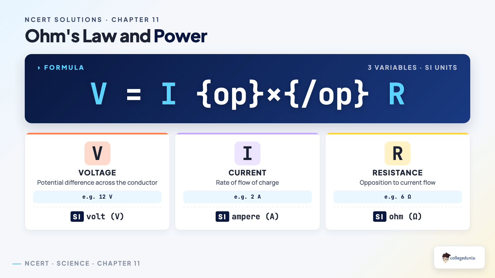
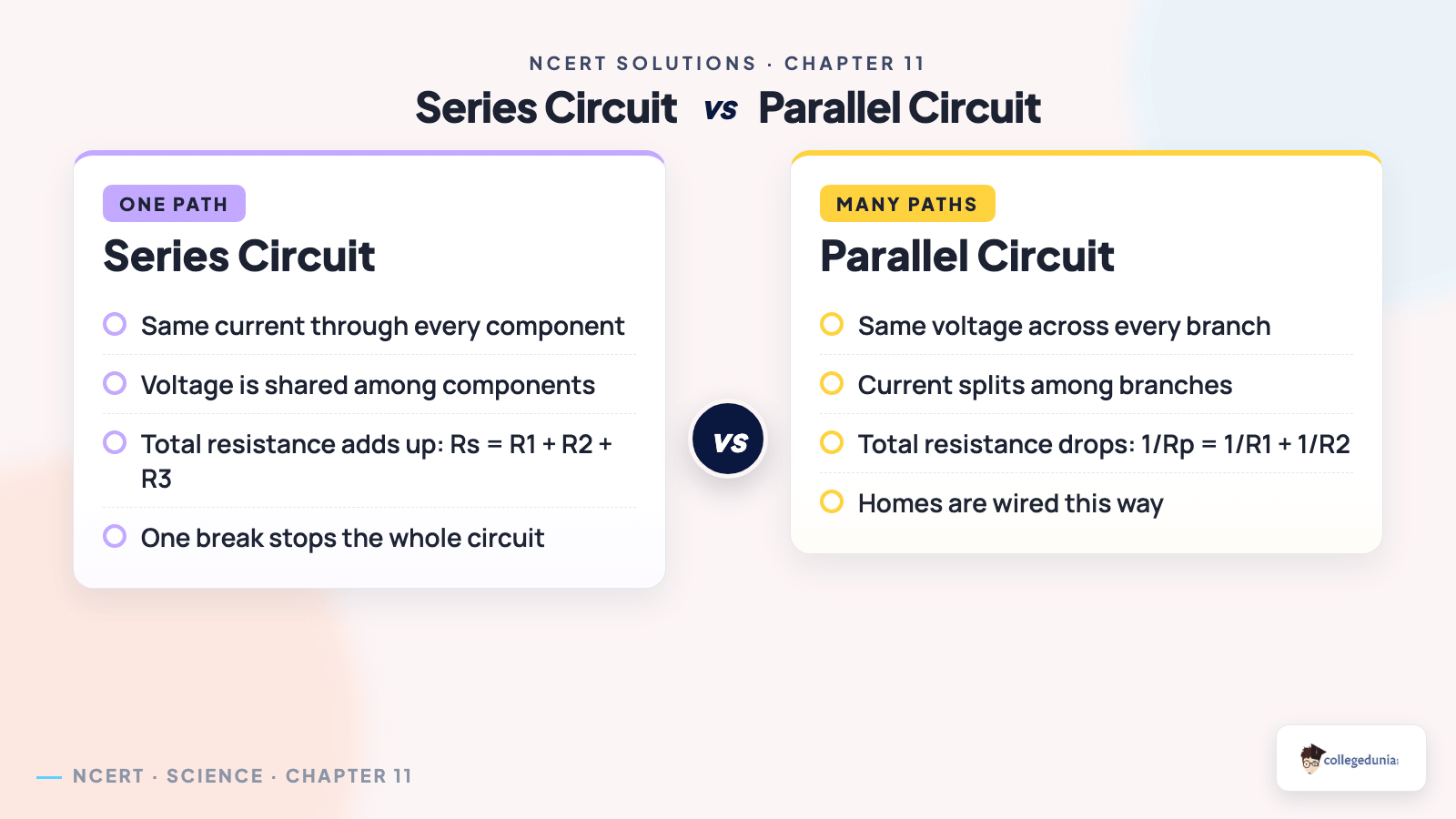


Comments