


Bihar Board Class 12 Physics Elective Question Paper 2023 with Answer Key pdf is available for download here. The exam was conducted by Bihar School Examination Board (BSEB). The question paper comprised a total of 96 questions divided among 2 sections.
Bihar Board Class 12 Physics Elective Question Paper 2023 with Answer Key
| Bihar Board Class 12 Physics Question Paper with Answer Key | Check Solutions |

When current in a coil changes from 5A to 2A in 0.1s then average voltage of 50V is produced. The self-inductance of the coil is
View Solution
Step 1: Understanding the Concept:
The question asks for the self-inductance of a coil. Self-inductance is the property of a coil by virtue of which it opposes any change in the strength of the current flowing through it by inducing an electromotive force (e.m.f.) in itself. This induced e.m.f. is also known as back e.m.f. The magnitude of this induced e.m.f. is directly proportional to the rate of change of current.
Step 2: Key Formula or Approach:
The formula for the average induced voltage (e.m.f., \(\epsilon\)) in a coil due to self-inductance (L) is given by Faraday's law of induction:
\[ \epsilon = -L \frac{dI}{dt} \]
Where:
\(\epsilon\) is the induced voltage (e.m.f.).
\(L\) is the self-inductance of the coil.
\(\frac{dI}{dt}\) is the rate of change of current.
For average values over a time interval \(\Delta t\), the formula can be written as:
\[ \epsilon_{avg} = -L \frac{\Delta I}{\Delta t} \]
The negative sign indicates that the induced e.m.f. opposes the change in current (Lenz's Law). For calculating the magnitude, we can use:
\[ |\epsilon_{avg}| = L \left| \frac{\Delta I}{\Delta t} \right| \]
Step 3: Detailed Explanation:
Given data:
Initial current, \(I_1 = 5 A\)
Final current, \(I_2 = 2 A\)
Time interval, \(\Delta t = 0.1 s\)
Average induced voltage, \(\epsilon = 50 V\)
First, we calculate the change in current (\(\Delta I\)):
\[ \Delta I = I_2 - I_1 = 2 A - 5 A = -3 A \]
Next, we calculate the rate of change of current \(\frac{\Delta I}{\Delta t}\):
\[ \frac{\Delta I}{\Delta t} = \frac{-3 A}{0.1 s} = -30 A/s \]
Now, we use the formula for induced voltage to find the self-inductance \(L\):
\[ \epsilon = -L \frac{\Delta I}{\Delta t} \] \[ 50 V = -L (-30 A/s) \] \[ 50 = 30L \]
Solving for \(L\):
\[ L = \frac{50}{30} H \] \[ L = \frac{5}{3} H \] \[ L \approx 1.67 H \]
Step 4: Final Answer:
The self-inductance of the coil is approximately 1.67 Henry. This corresponds to option (A).
Quick Tip: In problems involving induced e.m.f., always pay attention to the signs. The negative sign in Faraday's law (\(\epsilon = -L \frac{dI}{dt}\)) represents Lenz's law, which states that the induced e.m.f. opposes the change in current. When calculating the magnitude of inductance, you can often ignore the sign, but understanding its meaning is crucial for conceptual questions.
The concept of secondary wavelets was given by
View Solution
Step 1: Understanding the Concept:
The question asks to identify the scientist who proposed the concept of secondary wavelets. This concept is a fundamental part of the wave theory of light, used to explain phenomena like reflection, refraction, and diffraction.
Step 2: Detailed Explanation:
The concept of secondary wavelets was introduced by the Dutch physicist Christiaan Huygens in 1678.
Huygens' Principle states that:
1. Every point on a primary wavefront acts as a source of new disturbances, called secondary wavelets, which travel out in all directions with the same speed as the original wave.
2. The new wavefront at any later time is the forward envelope (the tangential surface in the forward direction) of these secondary wavelets.
This principle successfully explains the propagation of waves and phenomena like reflection and refraction. While Fresnel later modified and refined Huygens' principle to better explain diffraction (leading to the Huygens-Fresnel principle), the original concept of secondary wavelets is credited to Huygens.
- Fresnel built upon Huygens' work to explain diffraction by incorporating the principle of interference of the secondary wavelets.
- Maxwell developed the electromagnetic theory of light, describing light as electromagnetic waves.
- Newton proposed the corpuscular (particle) theory of light.
Step 3: Final Answer:
The concept of secondary wavelets was given by Huygens. Therefore, option (C) is the correct answer.
Quick Tip: Remember the key contributions of scientists in wave optics: Huygens gave the principle of secondary wavelets, Young demonstrated interference (double-slit experiment), and Fresnel explained diffraction by combining Huygens' principle with interference. Newton is associated with the particle theory of light, which contrasts with the wave theory.
In photoelectric effect, the photoelectric current is independent of
View Solution
Step 1: Understanding the Concept:
The photoelectric effect is the emission of electrons when electromagnetic radiation, such as light, hits a material. Photoelectric current is the flow of these emitted electrons (photoelectrons). The question asks which factor does not affect the magnitude of this current.
Step 2: Detailed Explanation:
Let's analyze the relationship between photoelectric current and the given options:
(A) Intensity of incident light: Photoelectric current is directly proportional to the intensity of the incident light (provided the frequency is above the threshold frequency). Higher intensity means more photons are striking the surface per unit time, which in turn ejects more electrons, leading to a larger current. So, the current is dependent on intensity.
(B) Potential difference applied between two electrodes: The potential difference can either accelerate or decelerate the photoelectrons. An accelerating potential helps more electrons reach the collector, increasing the current up to a saturation point. A retarding (negative) potential opposes the flow, decreasing the current. Thus, the current is dependent on the potential difference.
(C) The nature of emitter material: The material's nature determines its work function (\(\phi_0\)), which is the minimum energy required to eject an electron. This defines the threshold frequency (\(f_0\)). If the incident light's frequency is below \(f_0\), no current flows. So, the existence of the current depends on the material.
(D) Frequency of incident light: According to Einstein's photoelectric equation (\(K_{max} = hf - \phi_0\)), the frequency of the incident light determines the maximum kinetic energy of the emitted photoelectrons, not their number. As long as the frequency is above the threshold frequency (\(f > f_0\)), changing the frequency (while keeping the intensity constant) will change the speed of the electrons, but not the number of electrons emitted per second. Since the photoelectric current depends on the number of electrons emitted per second, it is independent of the frequency of the incident light.
Step 3: Final Answer:
The photoelectric current is independent of the frequency of the incident light (assuming the frequency is above the threshold). Therefore, option (D) is the correct answer.
Quick Tip: To easily remember the relationships in the photoelectric effect: \textbf{Intensity} \(\rightarrow\) \textbf{Number of electrons} \(\rightarrow\) \textbf{Photoelectric Current}. \textbf{Frequency} \(\rightarrow\) \textbf{Energy of electrons} \(\rightarrow\) \textbf{Kinetic Energy / Stopping Potential}. This helps distinguish between what affects the current and what affects the energy of the electrons.
In visible spectrum, which colour has larger wavelength ?
View Solution
Step 1: Understanding the Concept:
The visible spectrum is the portion of the electromagnetic spectrum that is visible to the human eye. It consists of a range of colors, each corresponding to a different wavelength of light. The question asks to identify the color with the largest wavelength.
Step 2: Detailed Explanation:
The colors of the visible spectrum are typically remembered by the acronym VIBGYOR, which stands for Violet, Indigo, Blue, Green, Yellow, Orange, and Red.
This sequence is arranged in order of increasing wavelength (or decreasing frequency and energy).
- Violet has the shortest wavelength (around 400 nm).
- Red has the longest wavelength (around 650-700 nm).
Therefore, among the given options, Red has the largest wavelength.
Step 3: Final Answer:
In the visible spectrum, Red has the largest wavelength. So, option (A) is correct.
Quick Tip: Use the acronym VIBGYOR to remember the order of colors in the visible spectrum. The order goes from the shortest wavelength (Violet) to the longest wavelength (Red). This also means Violet light has the highest frequency and energy, while Red light has the lowest.
The nucleus of any atom is made up of
View Solution
Step 1: Understanding the Concept:
This question asks about the composition of the atomic nucleus, which is the central, dense region of an atom.
Step 2: Detailed Explanation:
The nucleus of an atom is composed of two types of subatomic particles:
- Protons, which have a positive electrical charge.
- Neutrons, which are electrically neutral (have no charge).
These two particles, protons and neutrons, are collectively known as nucleons. They are held together in the nucleus by the strong nuclear force.
Let's analyze the other options:
- (A) proton: The nucleus contains protons, but for all elements except the most common isotope of hydrogen (protium), it also contains neutrons. So this is incomplete.
- (B) proton and electron: Electrons are negatively charged particles that orbit the nucleus; they are not part of the nucleus itself.
- (C) \(\alpha\)-particle: An alpha particle is the nucleus of a helium atom, consisting of two protons and two neutrons. While it is a type of nucleus, not all atomic nuclei are α-particles.
Step 3: Final Answer:
The nucleus of an atom is made up of protons and neutrons. Therefore, option (D) is the correct answer.
Quick Tip: Remember the basic structure of an atom: a central nucleus containing protons and neutrons, surrounded by a cloud of orbiting electrons. The number of protons defines the element, while the number of neutrons defines the isotope.
The phase-difference between current and voltage in only capacitive alternating current circuit is
View Solution
Step 1: Understanding the Concept:
In an alternating current (AC) circuit containing only a capacitor, the flow of current is related to the rate of change of voltage across the capacitor. This relationship causes a phase difference between the current and voltage waveforms.
Step 2: Detailed Explanation:
Let the alternating voltage applied to the circuit be \(V = V_m \sin(\omega t)\).
The charge on the capacitor at any instant is \(q = CV = CV_m \sin(\omega t)\).
The current in the circuit is the rate of flow of charge, so we differentiate the charge with respect to time:
\[ I = \frac{dq}{dt} = \frac{d}{dt} (CV_m \sin(\omega t)) \] \[ I = CV_m \omega \cos(\omega t) \]
To compare the phase of current and voltage, we express the current in terms of a sine function:
Since \(\cos(\theta) = \sin(\theta + \frac{\pi}{2})\), we can write:
\[ I = I_m \sin(\omega t + \frac{\pi}{2}) \]
Where \(I_m = V_m \omega C\) is the peak current.
Comparing the phase of voltage, \(\phi_V = \omega t\), with the phase of current, \(\phi_I = \omega t + \frac{\pi}{2}\), we find the phase difference:
\[ \Delta \phi = \phi_I - \phi_V = (\omega t + \frac{\pi}{2}) - \omega t = \frac{\pi}{2} \]
A phase difference of \(\frac{\pi}{2}\) radians is equal to 90°. The positive sign indicates that the current leads the voltage by 90°.
Step 3: Final Answer:
The phase-difference between current and voltage in a purely capacitive AC circuit is 90° (or \(\pi/2\) radians), with the current leading the voltage. Therefore, option (B) is correct.
Quick Tip: A useful mnemonic to remember the phase relationship in AC circuits is "CIVIL": In a \textbf{C}apacitor (C), \textbf{I} (current) leads \textbf{V} (voltage). In an \textbf{I}nductor (L), \textbf{V} (voltage) leads \textbf{I} (current). This helps you quickly recall that for a capacitor, the phase difference is 90° with current ahead.
Which one of the following electromagnetic radiations has minimum wavelength ?
View Solution
Step 1: Understanding the Concept:
The electromagnetic (EM) spectrum is the range of all types of EM radiation. Radiation is classified by wavelength, frequency, or energy. Wavelength (\(\lambda\)) and frequency (\(f\)) are inversely related (\(c = f\lambda\)), and energy (\(E\)) is directly proportional to frequency (\(E = hf\)). Therefore, minimum wavelength corresponds to maximum frequency and maximum energy.
Step 2: Detailed Explanation:
Let's arrange the given electromagnetic radiations in order of decreasing wavelength (or increasing frequency/energy):
1. Microwaves: Wavelengths range from about 1 meter to 1 millimeter. They have longer wavelengths and lower energy than the other options.
2. Ultraviolet (UV): Wavelengths are shorter than visible light, typically from 400 nm to 10 nm.
3. X-rays: Wavelengths are shorter than UV rays, typically from 10 nm to 0.01 nm.
4. γ-rays (Gamma rays): They have the shortest wavelengths in the entire electromagnetic spectrum, typically less than 0.01 nm (or 10 picometers). They are the most energetic form of electromagnetic radiation.
The order from longest to shortest wavelength is: Microwaves > Ultraviolet > X-rays > γ-rays.
Step 3: Final Answer:
Among the given options, γ-rays have the minimum wavelength. Therefore, option (D) is correct.
Quick Tip: Remember the order of the electromagnetic spectrum: "Roman Men Invented Very Unusual X-ray Guns" (Radio, Microwaves, Infrared, Visible, Ultraviolet, X-rays, Gamma rays). This mnemonic lists the radiations in order of decreasing wavelength and increasing frequency/energy.
The binary equivalent of 25 is
View Solution
Step 1: Understanding the Concept:
The question asks to convert a decimal number (base-10) to its binary equivalent (base-2). The standard method for this is the repeated division by 2.
Step 2: Key Formula or Approach:
To convert a decimal number to binary, we repeatedly divide the decimal number by 2 and record the remainders. The process continues until the quotient becomes 0. The binary number is then obtained by reading the remainders from the bottom up.
Step 3: Detailed Explanation:
Let's convert the decimal number 25 to binary:
Divide 25 by 2: Quotient = 12, Remainder = 1
Divide 12 by 2: Quotient = 6, Remainder = 0
Divide 6 by 2: Quotient = 3, Remainder = 0
Divide 3 by 2: Quotient = 1, Remainder = 1
Divide 1 by 2: Quotient = 0, Remainder = 1
Reading the remainders from the bottom up gives us 11001.
So, \( (25)_{10} = (11001)_2 \).
Alternatively, we can express 25 as a sum of powers of 2:
The powers of 2 are ..., 32, 16, 8, 4, 2, 1.
25 can be written as:
\[ 25 = 16 + 8 + 1 \] \[ 25 = (1 \times 2^4) + (1 \times 2^3) + (0 \times 2^2) + (0 \times 2^1) + (1 \times 2^0) \]
The coefficients of the powers of 2 give the binary representation: 11001.
Step 4: Final Answer:
The binary equivalent of 25 is (11001)\(_2\). This corresponds to option (C).
Quick Tip: When converting decimal to binary, quickly check your answer by converting it back. For (11001)\(_2\), the decimal value is \(1 \cdot 2^4 + 1 \cdot 2^3 + 0 \cdot 2^2 + 0 \cdot 2^1 + 1 \cdot 2^0 = 16 + 8 + 0 + 0 + 1 = 25\). This confirms the result.
The width of diffraction fringes is .......... to the width of interference fringes.
View Solution
Step 1: Understanding the Concept:
This question compares the fringe widths in two key wave optics phenomena: interference (typically from a double-slit) and diffraction (typically from a single-slit). Fringe width refers to the separation between consecutive bright or dark bands in the pattern.
Step 2: Detailed Explanation:
Interference Fringes (e.g., Young's Double-Slit Experiment):
In the interference pattern produced by two coherent sources, all the bright and dark fringes have the same width. The fringe width (\(\beta\)) is given by the formula \(\beta = \frac{\lambda D}{d}\), where \(\lambda\) is the wavelength, \(D\) is the distance to the screen, and \(d\) is the slit separation. This width is constant across the pattern. The intensity of all bright fringes is also the same.
Diffraction Fringes (e.g., Single-Slit Diffraction):
In the diffraction pattern produced by a single slit, the fringes are not of equal width. The central bright fringe (central maximum) is much wider and more intense than the other fringes (secondary maxima). The width of the central maximum is twice the width of any of the secondary maxima. The width of the central maximum is given by \(\frac{2\lambda D}{a}\), while the width of the secondary maxima is \(\frac{\lambda D}{a}\), where \(a\) is the slit width. Also, the intensity of the secondary maxima decreases rapidly as we move away from the center.
Comparison:
Interference fringes are of equal width and intensity.
Diffraction fringes are of unequal width and intensity.
Therefore, the width of diffraction fringes is unequal when compared to each other, and fundamentally different from the uniform width of interference fringes.
Step 3: Final Answer:
The statement implies a general comparison. Since diffraction fringes are not of uniform width, while interference fringes are, the correct description is that they are unequal. Thus, option (B) is the most appropriate answer.
Quick Tip: A key visual difference to remember is that an interference pattern is a series of uniformly spaced bright bands of equal brightness, while a diffraction pattern is dominated by a very wide and bright central band, with much narrower and dimmer bands on either side.
Light year is equal to
View Solution
Step 1: Understanding the Concept:
A light-year is a unit of astronomical distance. It is defined as the total distance that a beam of light, moving in a vacuum, travels in one Julian year (365.25 days). It is a unit of distance, not time.
Step 2: Key Formula or Approach:
The distance can be calculated using the formula:
\[ Distance = Speed \times Time \]
Step 3: Detailed Explanation:
The values needed for the calculation are:
Speed of light in vacuum (\(c\)) \(\approx 299,792,458 m/s \approx 3 \times 10^8 m/s\)
Time (\(t\)) = 1 Julian year = 365.25 days
First, we need to convert the time from years to seconds:
\[ t = 365.25 days \times 24 \frac{hours}{day} \times 60 \frac{minutes}{hour} \times 60 \frac{seconds}{minute} \] \[ t = 31,557,600 seconds \]
Now, calculate the distance:
\[ Distance = (299,792,458 m/s) \times (31,557,600 s) \] \[ Distance \approx 9,460,730,472,580,800 m \]
In scientific notation, this is approximately:
\[ Distance \approx 9.46 \times 10^{15} m \]
Step 4: Final Answer:
One light-year is equal to approximately 9.46 x 10\(^{15}\) meters. This matches option (A).
Quick Tip: Remember the order of magnitude for common astronomical distances. A light-year is a vast distance, on the order of 10\(^{15}\) meters or 10\(^{12}\) kilometers. An Astronomical Unit (AU, the distance from Earth to the Sun) is much smaller, about 1.5 x 10\(^{11}\) meters. A parsec is larger, about 3.26 light-years.
If any ammeter is shunted, then the total resistance of the circuit
View Solution
Step 1: Understanding the Concept:
An ammeter is a device used to measure current in a circuit and is always connected in series. A "shunted ammeter" refers to an ammeter (or more accurately, a galvanometer) that has a low-resistance resistor, called a shunt, connected in parallel with it. This is done to extend the range of the ammeter. The question asks what effect this has on the total resistance of the circuit.
Step 2: Key Formula or Approach:
When resistors are connected in parallel, the equivalent resistance (\(R_{eq}\)) is always less than the smallest individual resistance. The formula for two resistors in parallel is:
\[ R_{eq} = \frac{R_1 R_2}{R_1 + R_2} \]
Here, \(R_1\) is the ammeter's internal resistance (\(R_A\)), and \(R_2\) is the shunt resistance (\(R_S\)). The effective resistance of the shunted ammeter is \(R'_{A} = \frac{R_A R_S}{R_A + R_S}\).
Step 3: Detailed Explanation:
1. An ammeter is placed in series in a circuit. Let the original total resistance of the circuit be \(R_{total} = R_{circuit} + R_A\), where \(R_A\) is the ammeter's resistance and \(R_{circuit}\) is the resistance of the rest of the circuit.
2. When the ammeter is shunted, a low-resistance shunt (\(R_S\)) is connected in parallel to the ammeter's internal resistance (\(R_A\)).
3. The new effective resistance of the measuring instrument, \(R'_{A}\), is the parallel combination of \(R_A\) and \(R_S\).
4. Since the equivalent resistance of a parallel combination is always smaller than the smallest of the individual resistances, and a shunt has very low resistance, we have \(R'_{A} < R_S\). And since \(R_S\) is chosen to be much smaller than \(R_A\), it is certain that \(R'_{A} < R_A\).
5. The new total resistance of the circuit becomes \(R'_{total} = R_{circuit} + R'_{A}\).
6. Since \(R'_{A} < R_A\), it follows that \(R'_{total} < R_{total}\).
Therefore, shunting an ammeter decreases its own effective resistance, which in turn decreases the total resistance of the circuit it is part of.
Step 4: Final Answer:
If an ammeter is shunted, the total resistance of the circuit decreases. Option (B) is correct.
Quick Tip: Remember the rule for parallel resistors: adding a resistor in parallel to any part of a circuit always decreases the total equivalent resistance of that part. A shunt is simply a resistor added in parallel.
The temperature coefficient of a semi-conductor is
View Solution
Step 1: Understanding the Concept:
The temperature coefficient of resistance (\(\alpha\)) describes how the electrical resistance of a substance changes with a change in temperature. A positive coefficient means resistance increases with temperature, while a negative coefficient means resistance decreases with temperature.
Step 2: Detailed Explanation:
Conductors (Metals): In metals, as temperature increases, the positive ions vibrate more vigorously. This increases the frequency of collisions for the free electrons moving through the material, which in turn increases the electrical resistance. Therefore, conductors have a positive temperature coefficient of resistance.
Semi-conductors: In semi-conductors (like silicon and germanium), the electrical conductivity depends on the number of charge carriers (electrons and holes). At absolute zero, a pure semiconductor behaves like an insulator. As the temperature rises, thermal energy breaks covalent bonds, creating more electron-hole pairs. This increase in the number of charge carriers drastically increases the conductivity, and consequently, decreases the resistance.
Since the resistance of a semiconductor decreases as its temperature increases, it has a negative temperature coefficient of resistance.
Step 3: Final Answer:
The temperature coefficient of a semi-conductor is negative. Option (B) is correct.
Quick Tip: A simple way to remember this is: \textbf{Conductors}: Get "more resistive" (hotter) with heat \(\rightarrow\) \textbf{Positive} \(\alpha\). \textbf{Semi-conductors}: Get "less resistive" (more conductive) with heat \(\rightarrow\) \textbf{Negative} \(\alpha\). This behavior is a defining characteristic that distinguishes semiconductors from metals.
If T is time period and V is maximum speed of a charged particle in cyclotron, then
View Solution
Note: In a standard, non-relativistic cyclotron, the time period of revolution of a charged particle is independent of its speed and the radius of its orbit. This is the fundamental principle upon which the cyclotron operates. Therefore, none of the given proportionality options are correct. We will proceed by deriving the correct relationship.
Step 1: Understanding the Concept:
A cyclotron accelerates charged particles using a constant magnetic field and an oscillating electric field. The magnetic field forces the particle to move in a circular path, and the electric field accelerates it each time it crosses the gap between the two "dee" electrodes. The question asks for the relationship between the time period of one revolution (T) and the particle's speed (V).
Step 2: Key Formula or Approach:
The magnetic force (\(F_B\)) on the charged particle provides the necessary centripetal force (\(F_c\)) to keep it in a circular path.
\[ F_B = F_c \] \[ qvB = \frac{mv^2}{r} \]
The time period (T) is the time taken to complete one full circle, which is the circumference divided by the speed.
\[ T = \frac{2\pi r}{v} \]
Step 3: Detailed Explanation:
From the force balance equation, we can find an expression for the radius \(r\):
\[ qvB = \frac{mv^2}{r} \implies r = \frac{mv}{qB} \]
Now, substitute this expression for the radius \(r\) into the time period equation:
\[ T = \frac{2\pi}{v} \left( \frac{mv}{qB} \right) \]
The speed \(v\) cancels out from the numerator and the denominator:
\[ T = \frac{2\pi m}{qB} \]
This result shows that the time period \(T\) depends only on the mass (\(m\)) and charge (\(q\)) of the particle, and the strength of the magnetic field (\(B\)). It is independent of the particle's speed (\(v\)) and the radius of its orbit (\(r\)).
Step 4: Final Answer:
The time period \(T\) is independent of the speed \(V\). The correct relationship is \(T \propto V^0\). Since this is not among the options, the question is flawed.
Quick Tip: A core principle of the cyclotron is that the revolution period is constant. This allows the use of a fixed-frequency AC voltage to accelerate the particles. Remember the formula \(T = \frac{2\pi m}{qB}\); it clearly shows no dependence on velocity or radius. This independence breaks down at very high (relativistic) speeds, which is a limitation of the classic cyclotron.
Van de Graaff generator is an electrostatic machine which produces
View Solution
Step 1: Understanding the Concept:
A Van de Graaff generator is a device designed to create a very large static electric potential (voltage). It operates by using a moving belt to transport electric charge from a source to a large, hollow metal sphere.
Step 2: Detailed Explanation:
Voltage Production: The generator accumulates a large amount of charge on the outer surface of its spherical terminal. The potential of a sphere is given by \(V = kQ/R\). By continuously transporting charge (\(Q\)) to the sphere, a very high potential difference (voltage), often in the range of millions of volts, is built up with respect to the ground. Its primary function is to produce this high voltage.
Current Production: The charge is transported mechanically by a physical belt. The rate at which charge can be moved is limited, so the resulting electric current (\(I = dQ/dt\)) is very small, typically in the microampere (\(\mu A\)) range.
Conclusion: The defining characteristic of a Van de Graaff generator is its ability to produce extremely high voltages. The current it can deliver is, by contrast, very low. Therefore, among the given choices, "Only high voltage" is the best description of its output.
Step 3: Final Answer:
A Van de Graaff generator produces a very high voltage but a very low current. Option (B) correctly identifies its main output.
Quick Tip: Think of the Van de Graaff generator as a "charge pump". It works slowly (low current) but builds up a huge amount of pressure (high voltage). It is used in applications that require high potential to accelerate particles, such as in early particle accelerators and for educational demonstrations of static electricity.
S.I. unit of permittivity is
View Solution
Step 1: Understanding the Concept:
Permittivity (\(\epsilon\)) is a measure of how an electric field affects, and is affected by, a dielectric medium. The question asks for the SI unit of permittivity, often referring to the permittivity of free space, \(\epsilon_0\).
Step 2: Key Formula or Approach:
We can derive the unit of permittivity from Coulomb's Law, which describes the electrostatic force (\(F\)) between two point charges (\(q_1\) and \(q_2\)) separated by a distance (\(r\)).
\[ F = \frac{1}{4\pi\epsilon_0} \frac{q_1 q_2}{r^2} \]
Step 3: Detailed Explanation:
First, we rearrange Coulomb's Law to solve for \(\epsilon_0\):
\[ \epsilon_0 = \frac{1}{4\pi F} \frac{q_1 q_2}{r^2} \]
Now, we substitute the SI units for each physical quantity into the equation. The term \(4\pi\) is a dimensionless constant.
Unit of Force (\(F\)): Newton (N)
Unit of Charge (\(q_1, q_2\)): Coulomb (C)
Unit of Distance (\(r\)): meter (m)
Substituting these units:
\[ Unit of \epsilon_0 = \frac{1}{N} \cdot \frac{C \cdot C}{m^2} = \frac{C^2}{N \cdot m^2} \]
This unit can be written in exponent notation as:
\[ C^2 N^{-1} m^{-2} \]
Step 4: Final Answer:
The SI unit of permittivity is C\(^2\) N\(^{-1}\) m\(^{-2}\). This matches option (D).
Quick Tip: Another common unit for permittivity is Farads per meter (F/m). You can verify that this is equivalent: \(1 F = 1 C/V\) and \(1 V = 1 J/C = 1 N \cdot m/C\). Therefore, \(1 F = 1 C^2 / (N \cdot m)\). Dividing by meters gives \(1 F/m = 1 C^2 / (N \cdot m^2)\). Remembering both units (F/m and C\(^2\) N\(^{-1}\) m\(^{-2}\)) can be helpful.
The net charge on a charged capacitor is
View Solution
Step 1: Understanding the Concept:
A capacitor is a device that stores electrical energy in an electric field. It typically consists of two conductive plates separated by an insulator (dielectric). The question asks for the net or total charge on the capacitor as a whole when it is charged.
Step 2: Detailed Explanation:
When a capacitor is connected to a voltage source (like a battery), the source moves electrons from one plate to the other.
- The plate that loses electrons becomes positively charged. Let's say it acquires a charge of \(+Q\).
- The plate that gains an equal number of electrons becomes negatively charged. It acquires a charge of \(-Q\).
The term "charge on a capacitor" conventionally refers to the magnitude of the charge on one of the plates (i.e., \(Q\)).
However, the *net charge* of the capacitor as a complete, isolated device is the algebraic sum of the charges on both plates.
\[ Q_{net} = (+Q) + (-Q) = 0 \]
Step 3: Final Answer:
Since one plate has a charge of \(+Q\) and the other has a charge of \(-Q\), the total net charge on the charged capacitor is zero. Therefore, option (A) is correct.
Quick Tip: Be careful with the wording. "Charge on a capacitor" usually means the magnitude of charge on the positive plate (\(Q\)). "Net charge on a capacitor" or "total charge of the capacitor" means the sum of charges on both plates, which is always zero for an isolated, charged capacitor.
The motion of an electron inside a conductor is
View Solution
Step 1: Understanding the Concept:
This question asks to describe the overall motion of a free electron inside a conductor when an electric field is applied (i.e., when a current is flowing).
Step 2: Detailed Explanation:
Free electrons in a conductor are in a state of continuous, random motion due to thermal energy, with very high speeds (thermal velocity). They frequently collide with the fixed positive ions of the metallic lattice.
When an external electric field is applied, the electrons experience an electrostatic force in the direction opposite to the field. This force accelerates the electrons. However, this acceleration lasts only for a very short time before the electron collides with a lattice ion. During the collision, the electron loses most of the energy gained from the field and its direction of motion is randomized. It then starts to accelerate again.
This process of acceleration followed by collision repeats continuously. While the instantaneous motion is a series of short accelerations, the *net effect* over a longer period is a slow, average movement in the direction opposite to the electric field. This net motion is called drift. The average velocity of this motion is called the drift velocity (\(v_d\)), which is typically very small (\(\sim 10^{-4}\) m/s) and is constant for a constant electric field.
- Uniform motion is incorrect because the instantaneous velocity is constantly changing.
- Accelerated motion is only partially correct; it describes the motion between collisions but not the overall effect.
- Retarded/Damped motion describes the effect of collisions but not the driving force from the field.
- Drifted motion is the best term to describe the overall, effective motion of the electron that gives rise to electric current.
Step 3: Final Answer:
The net or average motion of an electron inside a conductor under the influence of an electric field is a drift. Therefore, option (C) is the most accurate description.
Quick Tip: Visualize a person trying to walk through a dense, jostling crowd. They are constantly bumped and change direction (collisions), but by persistently pushing in one direction (electric field), they make slow, overall progress. This slow, net progress is the "drift". The electron's path is a chaotic series of short, curved paths, but with a net displacement over time.
The total electric flux coming out from stationary unit positive charge in air is
View Solution
Step 1: Understanding the Concept:
This question requires the application of Gauss's Law in electrostatics. Gauss's Law relates the total electric flux (\(\Phi_E\)) through any closed surface (called a Gaussian surface) to the net electric charge (\(Q_{enc}\)) enclosed by that surface.
Step 2: Key Formula or Approach:
Gauss's Law is stated mathematically as:
\[ \Phi_E = \oint \vec{E} \cdot d\vec{A} = \frac{Q_{enc}}{\epsilon} \]
Where:
\(\Phi_E\) is the total electric flux.
\(Q_{enc}\) is the total charge enclosed within the surface.
\(\epsilon\) is the permittivity of the medium. For air or vacuum, we use the permittivity of free space, \(\epsilon_0\).
Step 3: Detailed Explanation:
According to the problem statement:
- The charge is a "unit positive charge", which means \(Q_{enc} = +1\) C.
- The medium is "air", so we use the permittivity \(\epsilon_0\).
Substituting these values into Gauss's Law:
\[ \Phi_E = \frac{+1}{\epsilon_0} \]
This can be written using a negative exponent as:
\[ \Phi_E = (\epsilon_0)^{-1} \]
Step 4: Final Answer:
The total electric flux is \((\epsilon_0)^{-1}\). This corresponds to option (B).
Quick Tip: Gauss's Law is a powerful tool for calculating electric flux. Remember that the flux depends only on the enclosed charge, not on the shape or size of the Gaussian surface. For a point charge, the flux is the same through a small sphere around it as it is through a large, irregularly shaped surface enclosing it.
The force, acting on per unit charge is called
View Solution
Step 1: Understanding the Concept:
This question asks for the definition of a fundamental quantity in electrostatics. We need to identify the physical quantity that is defined as the electrostatic force experienced by a charge divided by the magnitude of that charge.
Step 2: Detailed Explanation:
Let's analyze the definitions of the given options:
- Electric current is the rate of flow of electric charge (\(I = dQ/dt\)). It is not force per unit charge.
- Electric potential at a point is the work done in moving a unit positive charge from a reference point (usually infinity) to that point (\(V = W/q\)). It is energy per unit charge, not force per unit charge.
- Electric field (or electric field intensity, \(\vec{E}\)) at a point is defined as the electrostatic force (\(\vec{F}\)) experienced by a small positive test charge (\(q_0\)) placed at that point, divided by the magnitude of the test charge.
\[ \vec{E} = \frac{\vec{F}}{q_0} \]
This exactly matches the description "force, acting on per unit charge".
- Electric space is not a standard term in physics for a physical quantity.
Step 3: Final Answer:
The force per unit charge is the definition of the electric field. Therefore, option (C) is correct.
Quick Tip: Remember the key "per unit charge" definitions: \textbf{Force} per unit charge = \textbf{Electric Field} (\(E=F/q\)). \textbf{Potential Energy} per unit charge = \textbf{Electric Potential} (\(V=U/q\)). This distinction is crucial for solving problems in electrostatics.
Quantisation of charge indicates that
View Solution
Step 1: Understanding the Concept:
The principle of "quantisation of charge" is a fundamental property of electric charge. It states that electric charge is not continuous but exists in discrete packets.
Step 2: Detailed Explanation:
The principle of quantisation of charge states that the total charge (\(Q\)) on any object is always an integer multiple of a basic unit of charge, denoted by \(e\). This basic unit is the magnitude of the charge of a single electron or proton (\(e \approx 1.602 \times 10^{-19}\) C).
The formula is: \(Q = ne\), where \(n\) is an integer (\(n = 0, \pm 1, \pm 2, \ldots\)).
Let's evaluate the given options based on this principle:
(A) Charge, which is a fraction of charge on an electron, is not possible: This is a direct consequence of the rule \(Q = ne\). Since \(n\) must be an integer, it is impossible for an isolated object to have a charge of, for example, 0.5\(e\) or 1.7\(e\). This statement accurately describes quantisation.
(B) A charge cannot be destroyed: This describes the law of conservation of charge, which is a different principle.
(C) Charge exists on particles: This is a true statement, but it is not the meaning of quantisation.
(D) There exists a minimum permissible charge on a particle: This is also a consequence of quantisation (the minimum non-zero charge is \(e\)), but option (A) is a more complete and precise statement of the principle. It explains *why* there is a minimum charge and also rules out all non-integer multiples, not just those below the minimum.
Step 3: Final Answer:
The most accurate and comprehensive description of the quantisation of charge among the choices is that charge cannot exist as a fraction of the elementary charge \(e\). Therefore, option (A) is the best answer.
Quick Tip: Distinguish between the three fundamental properties of charge: 1. \textbf{Quantisation}: Charge comes in integer multiples of \(e\). (\(Q=ne\)). 2. \textbf{Conservation}: The total charge of an isolated system remains constant. 3. \textbf{Additivity}: The total charge of a system is the algebraic sum of individual charges.
Electric field lines provide information about
View Solution
Step 1: Understanding the Concept:
Electric field lines are a visual tool used to represent electric fields. They have several properties that convey information about the field and the charges creating it.
Step 2: Detailed Explanation:
Let's examine what information can be obtained from electric field lines:
(A) Field strength: The density of the electric field lines (how close they are to one another) in a region is proportional to the magnitude, or strength, of the electric field in that region. Where the lines are close together, the field is strong; where they are far apart, the field is weak.
(B) Direction: The tangent to an electric field line at any point gives the direction of the electric field vector \(\vec{E}\) at that point. The arrowhead on the line indicates the direction of the force that would be exerted on a positive test charge.
(C) Nature of charge: Electric field lines originate from positive charges and terminate on negative charges (or extend to infinity). By observing the pattern of where lines begin and end, we can determine the location and nature (positive or negative) of the source charges.
Since electric field lines provide information about field strength, direction, and the nature of the charge, all the given options are correct.
Step 3: Final Answer:
Electric field lines provide information about all the listed properties. Therefore, option (D) is the correct answer.
Quick Tip: Remember these key rules for electric field lines: 1. They point from positive to negative. 2. They never cross each other. 3. Their density indicates field strength. 4. They are perpendicular to the surface of conductors in electrostatic equilibrium.
Nickel is
View Solution
Step 1: Understanding the Concept:
Materials are classified based on their behavior in an external magnetic field. The main categories are diamagnetic, paramagnetic, and ferromagnetic.
Step 2: Detailed Explanation:
- Diamagnetic materials are weakly repelled by a magnetic field. They have a magnetic permeability slightly less than that of a vacuum. Examples include water, copper, and bismuth.
- Paramagnetic materials are weakly attracted to a magnetic field. They have a magnetic permeability slightly greater than that of a vacuum. Examples include aluminum, platinum, and oxygen.
- Ferromagnetic materials are very strongly attracted to a magnetic field and can be permanently magnetized. They have a very high magnetic permeability. The atoms in these materials have magnetic moments that align in large regions called domains.
Nickel (Ni) is one of the three common elements, along with Iron (Fe) and Cobalt (Co), that exhibit ferromagnetism at room temperature.
Step 3: Final Answer:
Nickel is a ferromagnetic material. Therefore, option (C) is correct.
Quick Tip: Remember the "big three" ferromagnetic elements: Iron (Fe), Cobalt (Co), and Nickel (Ni). These are the most common examples asked in exams.
The angle between magnetic meridian and geographical meridian is called
View Solution
Step 1: Understanding the Concept:
This question asks for the definition of one of the elements of Earth's magnetic field, which are used to describe the field at any point on the Earth's surface.
Step 2: Detailed Explanation:
Let's define the key terms:
- Geographical Meridian: An imaginary vertical plane passing through a point on the Earth's surface and the Earth's axis of rotation (i.e., passing through the geographic North and South poles). It defines the direction of true north.
- Magnetic Meridian: An imaginary vertical plane at a point on the Earth's surface which contains the direction of the horizontal component of the Earth's magnetic field. A freely suspended compass needle aligns itself in this plane. It defines the direction of magnetic north.
- Angle of Declination (\(\theta\)): The angle between the geographical meridian and the magnetic meridian at a place. It is the angle by which a compass needle deviates from true north.
- Angle of Dip (\(\delta\)): The angle between the direction of the Earth's total magnetic field and the horizontal direction in the magnetic meridian.
The question asks for the angle between the magnetic meridian and the geographical meridian, which is the definition of the angle of declination.
Step 3: Final Answer:
The angle between the magnetic meridian and geographical meridian is called declination. Therefore, option (B) is correct.
Quick Tip: Think of it this way: \textbf{De}clination tells you how much to \textbf{de}viate your compass from true north. \textbf{Dip} tells you how much the magnetic field vector \textbf{dip}s below the horizontal.
The radius of curvature of each surface of a biconvex lens is 20 cm and the refractive index of the material of the lens is 1.5. The focal length of the lens is
View Solution
Step 1: Understanding the Concept:
The problem requires finding the focal length of a biconvex lens given its radii of curvature and refractive index. This can be solved using the Lens Maker's Formula.
Step 2: Key Formula or Approach:
The Lens Maker's Formula is: \[ \frac{1}{f} = (\mu - 1) \left( \frac{1}{R_1} - \frac{1}{R_2} \right) \]
where: \(f\) = focal length of the lens \(\mu\) = refractive index of the lens material with respect to the surrounding medium (air, in this case) \(R_1\) = radius of curvature of the first surface (where light enters) \(R_2\) = radius of curvature of the second surface
Step 3: Detailed Explanation:
Given data:
- Type of lens: Biconvex
- Refractive index, \(\mu = 1.5\)
- Radius of curvature of each surface = 20 cm.
We must apply the Cartesian sign convention. Assume light travels from left to right.
- For the first surface (left), it is convex towards the incident light. Its center of curvature is on the right side. Thus, \(R_1 = +20\) cm.
- For the second surface (right), it is also convex, but its center of curvature is on the left side. Thus, \(R_2 = -20\) cm.
Now, substitute these values into the Lens Maker's Formula: \[ \frac{1}{f} = (1.5 - 1) \left( \frac{1}{+20} - \frac{1}{-20} \right) \] \[ \frac{1}{f} = (0.5) \left( \frac{1}{20} + \frac{1}{20} \right) \] \[ \frac{1}{f} = (0.5) \left( \frac{2}{20} \right) \] \[ \frac{1}{f} = \left(\frac{1}{2}\right) \left( \frac{1}{10} \right) \] \[ \frac{1}{f} = \frac{1}{20} \]
Therefore, the focal length is: \[ f = 20 cm \]
Step 4: Final Answer:
The focal length of the lens is 20 cm. This corresponds to option (C).
Quick Tip: For a symmetric biconvex lens (\(R_1 = R, R_2 = -R\)) made of a material with \(\mu=1.5\), the focal length is simply equal to the radius of curvature (\(f=R\)). This is a useful shortcut to remember for quick checks.
Which physical quantity will be the same for an electron and a photon of the same wavelength?
View Solution
Step 1: Understanding the Concept:
This question deals with the wave-particle duality, specifically the de Broglie wavelength for matter particles (like electrons) and the properties of photons. We need to compare different physical quantities for an electron and a photon that share the same wavelength \(\lambda\).
Step 2: Key Formula or Approach:
The key relationship connecting wavelength and momentum is the de Broglie relation, which applies to both matter particles and photons.
\[ p = \frac{h}{\lambda} \]
where \(p\) is momentum, \(h\) is Planck's constant, and \(\lambda\) is the wavelength.
Step 3: Detailed Explanation:
Let's analyze each quantity for an electron and a photon with the same wavelength \(\lambda\).
(A) Velocity: A photon always travels at the speed of light, \(c\). An electron has rest mass, so its speed \(v\) must be less than \(c\). Therefore, their velocities are not the same.
(B) Energy:
- The energy of a photon is given by \(E_{photon} = hf = \frac{hc}{\lambda}\).
- The kinetic energy of a non-relativistic electron is \(E_{electron} = \frac{p^2}{2m} = \frac{(h/\lambda)^2}{2m} = \frac{h^2}{2m\lambda^2}\).
Since the formulas are different, their energies will not be the same.
(C) Momentum:
- The momentum of a photon is given by \(p_{photon} = \frac{h}{\lambda}\).
- The de Broglie momentum of an electron is given by \(p_{electron} = \frac{h}{\lambda}\).
Since both \(h\) and \(\lambda\) are the same for the electron and the photon, their momenta must be equal.
(D) Angular momentum: This quantity is not inherently defined just by wavelength and would depend on other conditions (like orbital motion), so it is not guaranteed to be the same.
Step 4: Final Answer:
For the same wavelength \(\lambda\), both the electron and the photon will have the same momentum, \(p = h/\lambda\). Thus, option (C) is correct.
Quick Tip: The de Broglie relation \(p = h/\lambda\) is universal. It's the bridge that connects the particle property (momentum, \(p\)) to the wave property (wavelength, \(\lambda\)) for any quantum entity, whether it's a photon or a particle with mass.
The function of moderator in nuclear reactor is to
View Solution
Step 1: Understanding the Concept:
A nuclear reactor generates energy through a controlled nuclear chain reaction. In reactors using uranium-235, the fission process is most efficiently initiated by slow-moving neutrons, often called thermal neutrons.
Step 2: Detailed Explanation:
The fission of a uranium nucleus releases high-energy, fast-moving neutrons.
These fast neutrons are not very effective at causing fission in other uranium nuclei, as the probability of capture and fission is much lower at high energies.
To sustain the chain reaction efficiently, these fast neutrons must be slowed down to thermal energies.
The material used for this purpose is called a moderator.
The moderator consists of light nuclei (like hydrogen in water or carbon in graphite) that slow down the neutrons through a series of elastic collisions without absorbing them.
Therefore, the primary function of a moderator is to reduce the kinetic energy, or slow the speed, of fast neutrons.
Step 3: Final Answer:
Based on the explanation, the function of a moderator is to slow the speed of neutrons to sustain the nuclear chain reaction. Thus, option (A) is correct.
Quick Tip: Commonly used moderators in nuclear reactors are ordinary water (H\(_2\)O), heavy water (D\(_2\)O), and graphite. Remember that the moderator's job is to 'moderate' or slow down the neutron speed, not to absorb them (that's the job of control rods, which are made of neutron-absorbing materials like Cadmium or Boron).
The impurity element used for p-type semiconductor is
View Solution
Step 1: Understanding the Concept:
Semiconductors like Silicon (Si) and Germanium (Ge) belong to Group 14 of the periodic table and are tetravalent (have 4 valence electrons). Their electrical conductivity can be significantly increased by adding a small amount of a suitable impurity, a process called doping. This creates extrinsic semiconductors.
Step 2: Detailed Explanation:
p-type semiconductor: This type is formed when a tetravalent semiconductor (like Si) is doped with a trivalent impurity (an element with 3 valence electrons, from Group 13). The trivalent impurity atom replaces a silicon atom in the crystal lattice. It forms covalent bonds with three neighboring Si atoms, but there is a deficiency of one electron to bond with the fourth Si atom. This deficiency is called a "hole," which acts as a positive charge carrier.
n-type semiconductor: This type is formed by doping with a pentavalent impurity (an element with 5 valence electrons, from Group 15). The fifth electron is loosely bound and can easily become a free electron, acting as a negative charge carrier.
Step 3: Analyzing the Options:
(A) Boron (B): Belongs to Group 13, it is trivalent. Doping with Boron creates holes, resulting in a p-type semiconductor.
(B) Bismuth (Bi): Belongs to Group 15, it is pentavalent. Used for n-type doping.
(C) Arsenic (As): Belongs to Group 15, it is pentavalent. Used for n-type doping.
(D) Phosphorus (P): Belongs to Group 15, it is pentavalent. Used for n-type doping.
Step 4: Final Answer:
To create a p-type semiconductor, a trivalent impurity is required. Among the given options, only Boron is a trivalent element. Therefore, option (A) is correct.
Quick Tip: A helpful mnemonic to remember dopants is: \textbf{B-Al-Ga-In-Tl} (Elements of Group 13) are trivalent impurities that create \textbf{p-type} semiconductors (they are acceptor atoms). \textbf{P-As-Sb-Bi} (Elements of Group 15) are pentavalent impurities that create \textbf{n-type} semiconductors (they are donor atoms).
Diode is used as
View Solution
Step 1: Understanding the Concept:
A semiconductor diode (typically a p-n junction diode) is a two-terminal electronic component whose fundamental characteristic is that it allows electric current to flow easily in one direction (forward bias) while severely restricting it in the opposite direction (reverse bias).
Step 2: Detailed Explanation:
This property of allowing unidirectional current flow is the key principle behind rectification.
Rectification is the process of converting alternating current (AC), which periodically reverses its direction, into direct current (DC), which flows in only one direction.
A diode, when placed in an AC circuit, acts like a one-way electrical valve. It allows either the positive or negative half-cycles of the AC waveform to pass through while blocking the other half. This converts the AC into a pulsating DC.
Step 3: Analyzing the Options:
(A) Amplifier: A device that increases the amplitude of an electrical signal. This is the primary function of a transistor.
(B) Oscillator: A circuit that produces a continuous, repeated, alternating waveform without any input. Transistors or op-amps are typically used.
(C) Modulator: A device used in communications to superimpose a message signal onto a high-frequency carrier wave.
(D) Rectifier: A device that converts AC to DC. This is the most fundamental application of a diode.
Step 4: Final Answer:
The primary and most common application of a diode is to function as a rectifier due to its ability to conduct current in only one direction. Therefore, option (D) is correct.
Quick Tip: Think of the arrow in the diode's circuit symbol. The arrow points in the direction of conventional current flow (from the p-side/anode to the n-side/cathode). This visual cue helps to remember its function as a one-way gate for current, which is the essence of rectification.
Three capacitors of capacitance 6 µF are available. The minimum and maximum capacitances obtained are
View Solution
Step 1: Understanding the Concept:
To obtain the maximum equivalent capacitance from a set of capacitors, they should be connected in parallel. To obtain the minimum equivalent capacitance, they should be connected in series.
Step 2: Key Formula or Approach:
Given three capacitors, each with capacitance \( C = 6 \, \mu F \).
For Parallel Combination (Maximum Capacitance):
The equivalent capacitance \(C_{p}\) is the sum of individual capacitances. \[ C_{max} = C_1 + C_2 + C_3 \]
For Series Combination (Minimum Capacitance):
The reciprocal of the equivalent capacitance \(C_{s}\) is the sum of the reciprocals of individual capacitances. \[ \frac{1}{C_{min}} = \frac{1}{C_1} + \frac{1}{C_2} + \frac{1}{C_3} \]
Step 3: Detailed Explanation:
Calculation for Maximum Capacitance (Parallel):
Connect all three 6 µF capacitors in parallel. \[ C_{max} = 6 \, \mu F + 6 \, \mu F + 6 \, \mu F = 18 \, \mu F \]
Calculation for Minimum Capacitance (Series):
Connect all three 6 µF capacitors in series. \[ \frac{1}{C_{min}} = \frac{1}{6} + \frac{1}{6} + \frac{1}{6} = \frac{1+1+1}{6} = \frac{3}{6} = \frac{1}{2} \]
To find \(C_{min}\), we take the reciprocal: \[ C_{min} = 2 \, \mu F \]
Step 4: Final Answer:
The minimum capacitance obtained is 2 µF, and the maximum capacitance obtained is 18 µF. Therefore, option (C) is the correct choice.
Quick Tip: Remember that the rules for combining capacitors are the opposite of those for resistors. Capacitors in \textbf{parallel} add up like resistors in \textbf{series} (\(C_{eq} = C_1 + C_2 + \dots\)). Capacitors in \textbf{series} use the reciprocal formula, like resistors in \textbf{parallel} (\(1/C_{eq} = 1/C_1 + 1/C_2 + \dots\)).
The root mean square (r.m.s) value of alternating current equation I = 60 sin 100 πt is
View Solution
Step 1: Understanding the Concept:
The root mean square (r.m.s) value of an alternating current (AC) represents the effective DC value that would deliver the same average power to a resistor. For a sinusoidal current, it is directly related to its peak (maximum) value.
Step 2: Key Formula or Approach:
The general equation for a sinusoidal AC is given by: \[ I(t) = I_0 \sin(\omega t) \]
where \(I_0\) is the peak amplitude or maximum current.
The r.m.s value (\(I_{rms}\)) is related to the peak current by the formula: \[ I_{rms} = \frac{I_0}{\sqrt{2}} \]
Step 3: Detailed Explanation:
The given equation for the current is \(I = 60 \sin(100 \pi t)\).
By comparing this with the standard form \(I = I_0 \sin(\omega t)\), we can identify the peak current: \[ I_0 = 60 \, A \]
Now, we apply the formula for the r.m.s value: \[ I_{rms} = \frac{I_0}{\sqrt{2}} = \frac{60}{\sqrt{2}} \]
To simplify this expression, we rationalize the denominator by multiplying the numerator and denominator by \(\sqrt{2}\): \[ I_{rms} = \frac{60}{\sqrt{2}} \times \frac{\sqrt{2}}{\sqrt{2}} = \frac{60\sqrt{2}}{2} = 30\sqrt{2} \, A \]
Step 4: Final Answer:
The calculated r.m.s value is \(30\sqrt{2}\) A, which is approximately \(42.4\) A. This value does not match any of the given options. There appears to be an error in the question or the options. In such cases in an exam, it is common that there was a typo in the question. For instance, if the equation had been \(I = 30\sqrt{2} \sin(100 \pi t)\), then \(I_{rms}\) would be \(\frac{30\sqrt{2}}{\sqrt{2}} = 30\) A, matching option (B). Given the choices, it's highly probable this was the intended question. However, based strictly on the question provided, none of the options is correct.
Quick Tip: The RMS value for a sinusoidal waveform is always the peak value divided by \(\sqrt{2}\) (approximately 0.707 times the peak value). Conversely, the peak value is \(\sqrt{2}\) times the RMS value. This is a crucial relationship in AC circuit analysis. When your answer doesn't match, double-check your calculation and then look for plausible typos in the question.
The impedance of L-R circuit is
View Solution
Step 1: Understanding the Concept:
Impedance (\(Z\)) is the total opposition that a circuit presents to the flow of alternating current. In a series L-R circuit, it arises from two sources: the resistance (\(R\)) of the resistor and the inductive reactance (\(X_L\)) of the inductor. These two quantities do not add arithmetically because the voltage across the resistor is in phase with the current, while the voltage across the inductor leads the current by 90 degrees.
Step 2: Key Formula or Approach:
The resistance is \(R\).
The inductive reactance is given by \(X_L = \omega L\), where \(\omega\) is the angular frequency of the AC supply.
Since \(R\) and \(X_L\) are out of phase by 90°, they are combined as vectors (or phasors) using the Pythagorean theorem. This can be visualized using an impedance triangle where R is the adjacent side, \(X_L\) is the opposite side, and Z is the hypotenuse. \[ Z = \sqrt{R^2 + X_L^2} \]
Step 3: Detailed Explanation:
Substitute the expression for inductive reactance (\(X_L = \omega L\)) into the general formula for impedance: \[ Z = \sqrt{R^2 + (\omega L)^2} \]
This simplifies to: \[ Z = \sqrt{R^2 + \omega^2 L^2} \]
Step 4: Final Answer:
Comparing the derived expression with the given options, we see that option (D) correctly represents the impedance of a series L-R circuit.
Quick Tip: For any series RLC circuit, the impedance is \(Z = \sqrt{R^2 + (X_L - X_C)^2}\). For an L-R circuit, there is no capacitor, so \(X_C = 0\), which simplifies the formula to \(Z = \sqrt{R^2 + X_L^2}\). For an R-C circuit, \(X_L = 0\), so \(Z = \sqrt{R^2 + (-X_C)^2} = \sqrt{R^2 + X_C^2}\).
The radius of a circular current loop is made double and the current is made half. The magnetic moment of the loop will become
View Solution
Step 1: Understanding the Concept:
The magnetic dipole moment (\(\mu\)) of a current loop is a vector quantity that measures the strength and orientation of the magnetic field produced by the loop. Its magnitude is the product of the current flowing in the loop and the area enclosed by the loop.
Step 2: Key Formula or Approach:
The formula for the magnetic moment (\(\mu\)) of a current loop is: \[ \mu = I \cdot A \]
where \(I\) is the current and \(A\) is the area of the loop.
For a circular loop of radius \(r\), the area is \(A = \pi r^2\).
Therefore, the formula becomes: \[ \mu = I \pi r^2 \]
Step 3: Detailed Explanation:
Let the initial conditions be:
Initial current = \(I\)
Initial radius = \(r\)
So, the initial magnetic moment is \(\mu_{initial} = I \pi r^2\).
Now, the conditions are changed as follows:
New current, \(I' = \frac{I}{2}\) (halved)
New radius, \(r' = 2r\) (doubled)
Let's calculate the new magnetic moment (\(\mu_{new}\)) with these new values: \[ \mu_{new} = I' \cdot \pi (r')^2 \]
Substitute the expressions for \(I'\) and \(r'\): \[ \mu_{new} = \left(\frac{I}{2}\right) \cdot \pi (2r)^2 \] \[ \mu_{new} = \left(\frac{I}{2}\right) \cdot \pi (4r^2) \]
Rearrange the terms: \[ \mu_{new} = \left(\frac{4}{2}\right) \cdot (I \pi r^2) \] \[ \mu_{new} = 2 \cdot (I \pi r^2) \]
Since \(\mu_{initial} = I \pi r^2\), we can write: \[ \mu_{new} = 2 \cdot \mu_{initial} \]
Step 4: Final Answer:
The new magnetic moment is twice the initial magnetic moment. Therefore, the magnetic moment of the loop will be doubled. Option (B) is correct.
Quick Tip: For problems involving proportional changes, you can analyze the dependencies. Here, \(\mu \propto I\) and \(\mu \propto r^2\). So, \(\mu \propto I r^2\). The new moment \(\mu'\) will be proportional to \(I' (r')^2 = (\frac{1}{2}I)(2r)^2 = (\frac{1}{2})(4)Ir^2 = 2Ir^2\). Thus, the new moment is twice the original.
The self-inductance of a choke coil is 5 henry. The current through it is increasing at a rate of 2 AS\(^{-1}\). The self-induced emf in the choke coil will be
View Solution
Step 1: Understanding the Concept:
According to Faraday's law of induction and Lenz's law, when the current through an inductor changes, a back electromotive force (emf) is induced across it. This self-induced emf opposes the change in current.
Step 2: Key Formula or Approach:
The self-induced emf (\(\epsilon\)) in an inductor is given by the formula: \[ \epsilon = -L \frac{dI}{dt} \]
where:
\(L\) is the self-inductance of the coil.
\(\frac{dI}{dt}\) is the rate of change of current.
The negative sign indicates that the induced emf opposes the change in current (Lenz's Law).
Step 3: Detailed Explanation:
Given values are:
Self-inductance, \(L = 5\) H.
Rate of increase of current, \(\frac{dI}{dt} = 2\) A/s.
Substitute these values into the formula: \[ \epsilon = - (5 \, H) \times (2 \, A/s) \] \[ \epsilon = -10 \, V \]
Step 4: Final Answer:
The self-induced emf in the choke coil is -10 V. The negative sign signifies that the emf is induced in a direction that opposes the increase in current. Therefore, option (C) is the correct answer.
Quick Tip: Remember Lenz's law is represented by the negative sign in the formula \(\epsilon = -L \frac{dI}{dt}\). If the question asks for the magnitude of the induced emf, the answer would be 10 V. However, since -10 V is an option, it is the more precise answer as it includes the direction (polarity) of the emf.
Magnetic moment of the earth is
View Solution
Step 1: Understanding the Concept:
The Earth behaves like a large magnet with a magnetic field extending into space. This magnetic field is generated by the motion of molten iron alloys in its outer core. The strength of this magnetic field is quantified by its magnetic dipole moment. This is a factual, standard value in physics.
Step 2: Detailed Explanation:
The magnetic moment of the Earth has been measured through various geophysical methods. The currently accepted approximate value for the Earth's magnetic dipole moment is about \(8.0 \times 10^{22}\) Joules per Tesla (J T\(^{-1}\)).
The unit J T\(^{-1}\) is equivalent to Ampere-meter squared (A m\(^2\)), which is the standard SI unit for magnetic moment.
Let's check the options:
(A), (B), and (C) present values that are drastically different in magnitude from the known value.
(D) provides the correct order of magnitude and the standard value for the Earth's magnetic moment.
Step 3: Final Answer:
The accepted value for the magnetic moment of the Earth is approximately \(8.0 \times 10^{22}\) J T\(^{-1}\). Therefore, option (D) is correct.
Quick Tip: Some physical constants and standard values, like the charge of an electron, Planck's constant, and the magnetic moment of the Earth, are often asked in exams. It's beneficial to memorize the approximate values and their orders of magnitude.
The phase difference between electric wave and magnetic wave in the electromagnetic wave is
View Solution
Step 1: Understanding the Concept:
An electromagnetic (EM) wave consists of oscillating electric field (\(\vec{E}\)) and magnetic field (\(\vec{B}\)) vectors. These fields are perpendicular to each other and also perpendicular to the direction of wave propagation. A key characteristic of EM waves is the relationship between the phases of these two fields.
Step 2: Detailed Explanation:
According to Maxwell's equations for EM waves in a vacuum or free space, the electric and magnetic fields are always in phase. This means that they reach their maximum values at the same time and at the same point in space. Similarly, they both pass through zero and reach their minimum values simultaneously.
If the electric field is described by \(E = E_0 \sin(kx - \omega t)\), the magnetic field will be described by \(B = B_0 \sin(kx - \omega t)\).
The phase for both waves is the term \((kx - \omega t)\). Since the phase term is identical for both, the phase difference between them is zero.
Step 3: Final Answer:
The electric and magnetic fields in an electromagnetic wave oscillate in phase with each other. Therefore, the phase difference between them is zero. Option (D) is correct.
Quick Tip: Remember the key properties of EM waves: 1. \(\vec{E}\) and \(\vec{B}\) are mutually perpendicular. 2. The direction of propagation is given by \(\vec{E} \times \vec{B}\). 3. \(\vec{E}\) and \(\vec{B}\) are always in phase (phase difference is zero). 4. The ratio of their magnitudes is constant: \(E/B = c\) (speed of light).
When the distance between source of light and screen is increased, then fringe width
View Solution
Step 1: Understanding the Concept:
This question relates to the interference of light, typically observed in an experiment like Young's Double-Slit Experiment (YDSE). Fringe width is the distance between two consecutive bright or dark fringes on the screen.
Step 2: Key Formula or Approach:
The formula for the fringe width (\(\beta\)) in a double-slit interference pattern is: \[ \beta = \frac{\lambda D}{d} \]
where:
\(\lambda\) is the wavelength of the light used.
\(D\) is the distance between the slits (which act as the coherent sources) and the screen.
\(d\) is the distance between the two slits.
Step 3: Detailed Explanation:
The question states that the distance between the source of light (slits) and the screen is increased. This corresponds to an increase in the value of \(D\).
From the formula \(\beta = \frac{\lambda D}{d}\), we can see that the fringe width \(\beta\) is directly proportional to the distance \(D\), assuming \(\lambda\) and \(d\) are constant. \[ \beta \propto D \]
Therefore, if \(D\) increases, the fringe width \(\beta\) will also increase. This means the bright and dark fringes on the screen will become more spread out.
Step 4: Final Answer:
Since the fringe width is directly proportional to the distance between the source and the screen, increasing this distance will cause the fringe width to increase. Option (A) is correct.
Quick Tip: To get wide, easily visible fringes, you should increase the screen distance (\(D\)) and use light with a longer wavelength (\(\lambda\)), while keeping the slit separation (\(d\)) small. This relationship \(\beta = \lambda D/d\) is fundamental to wave optics problems.
The unit of radioactivity is
View Solution
Step 1: Understanding the Concept:
Radioactivity (or simply activity) of a radioactive sample is defined as the rate at which the nuclei of its constituent atoms decay. It is a measure of the number of disintegrations per unit time.
Step 2: Detailed Explanation:
Let's analyze the units given in the options:
(A) MeV (Mega-electron Volt): This is a unit of energy, commonly used in nuclear physics. \(1 \, MeV = 1.602 \times 10^{-13}\) Joules. It is not a unit of decay rate.
(B) Curie (Ci): This is a traditional unit of radioactivity. It is defined as \(1 \, Ci = 3.7 \times 10^{10}\) decays per second. It is a valid unit for radioactivity.
(C) a.m.u. (atomic mass unit): This is a unit of mass, used for atomic and subatomic particles. \(1 \, a.m.u. \approx 1.66 \times 10^{-27}\) kg. It is not a unit of decay rate.
(D) Joule (J): This is the SI unit of energy or work. It is not a unit of decay rate.
The SI unit of radioactivity is the Becquerel (Bq), where 1 Bq = 1 decay per second. The Curie is a larger, non-SI unit that is still widely used.
Step 3: Final Answer:
Among the given options, only the curie is a unit used to measure radioactivity. Therefore, option (B) is correct.
Quick Tip: Be careful to distinguish between units of energy (Joule, eV, MeV) and units of activity/radioactivity (Becquerel, Curie). Activity measures the 'how fast' of decay, while energy measures the 'how much' energy is released per decay.
Which of the following has the highest penetrating power?
View Solution
Step 1: Understanding the Concept:
Penetrating power is the ability of a form of radiation to pass through matter. The more a particle or ray interacts with the atoms of the material it passes through, the more quickly it loses its energy and the lower its penetrating power.
Step 2: Detailed Explanation:
Let's compare the penetrating power of the given radiations:
(A) \(\alpha\)-rays (Alpha particles): These are helium nuclei (\(^{4}_{2}He\)). They have a large mass and a double positive charge (+2e). Due to their strong charge and large size, they interact very strongly with matter through ionization. They lose their energy over a very short distance and have the \textit{lowest penetrating power. They can be stopped by a sheet of paper or even the outer layer of skin.
(B) \(\beta\)-rays (Beta particles): These are high-speed electrons or positrons. They are much lighter than alpha particles and have a single charge (-e or +e). They interact less strongly with matter than alpha particles, so they can penetrate further. They have a \textit{medium penetrating power and can be stopped by a few millimeters of aluminum.
(C) \(\gamma\)-rays (Gamma rays): These are high-energy photons (electromagnetic radiation). They have no mass and no charge. Because they are uncharged, they do not interact strongly via electrostatic forces and penetrate deeply into matter. They have the \textit{highest penetrating power and require thick layers of dense materials like lead or concrete to be significantly attenuated.
(D) Cathode rays: These are streams of electrons, essentially the same as beta particles but typically with lower energies found in cathode ray tubes. Their penetrating power is less than that of gamma rays and is comparable to beta particles.
Step 3: Final Answer:
Comparing the four options, gamma rays have the least interaction with matter due to their lack of charge and mass, giving them the highest penetrating power. Therefore, option (C) is correct.
Quick Tip: A simple way to remember the order of penetrating power is: \(\gamma > \beta > \alpha\). The opposite is true for ionizing power: \(\alpha > \beta > \gamma\). The more ionizing a particle is, the less penetrating it is.
Which range of frequency is used in TV transmission?
View Solution
Step 1: Understanding the Concept:
TV transmission requires a large bandwidth to carry both video (picture) and audio (sound) information. This necessitates the use of high-frequency carrier waves. The electromagnetic spectrum is divided into bands, and specific ranges are allocated for different communication purposes.
Step 2: Detailed Explanation:
Let's examine the frequency ranges given:
(A) 30 Hz - 300 Hz: This is the Extremely Low Frequency (ELF) range. These frequencies are in the audible range for humans and have very long wavelengths. They are not suitable for carrying the vast amount of information in a TV signal.
(B) 30 kHz - 300 kHz: This is the Low Frequency (LF) band. It is used for applications like AM radio broadcasting and navigation systems. The bandwidth is still insufficient for television.
(C) 30 MHz - 300 MHz: This is the Very High Frequency (VHF) band. This range provides sufficient bandwidth for TV signals and is historically the primary band used for terrestrial television broadcasting (e.g., channels 2-13 in North America).
(D) 30 GHz - 300 GHz: This is the Extremely High Frequency (EHF) band, also known as millimeter waves. This range is used for high-speed microwave data links, radio astronomy, and satellite communication, but not typically for conventional terrestrial TV broadcasting.
In addition to the VHF band, the Ultra High Frequency (UHF) band (300 MHz - 3 GHz) is also used for TV transmission. However, the range given in option (C) is the correct and standard band used for television.
Step 3: Final Answer:
The frequency range corresponding to the Very High Frequency (VHF) band, which is 30 MHz - 300 MHz, is used for TV transmission. Therefore, option (C) is correct.
Quick Tip: Remember the general order of the radio spectrum for communication: AM Radio (kHz), FM Radio \& TV (MHz), and Satellite \& Wi-Fi (GHz). This helps in quickly eliminating incorrect options in questions related to frequency bands.
The dispersive power of a prism depends on
View Solution
Step 1: Understanding the Concept:
Dispersive power (\(\omega\)) is a property of the material of a prism that quantifies its ability to separate white light into its constituent colors (dispersion). It is defined as the ratio of the angular dispersion (the difference in deviation angles for two extreme colors, typically violet and red) to the deviation of a mean color (typically yellow).
Step 2: Key Formula or Approach:
The formula for dispersive power (\(\omega\)) is: \[ \omega = \frac{Angular Dispersion}{Mean Deviation} = \frac{\delta_V - \delta_R}{\delta_Y} \]
For a prism with a small angle \(A\), the angle of deviation \(\delta\) is given by \(\delta = (\mu - 1)A\), where \(\mu\) is the refractive index of the material.
Substituting this into the formula for \(\omega\): \[ \omega = \frac{(\mu_V - 1)A - (\mu_R - 1)A}{(\mu_Y - 1)A} \]
The prism angle \(A\) cancels out from the numerator and the denominator: \[ \omega = \frac{\mu_V - \mu_R}{\mu_Y - 1} \]
Step 3: Detailed Explanation:
The final expression, \(\omega = \frac{\mu_V - \mu_R}{\mu_Y - 1}\), shows that the dispersive power depends only on the refractive indices of the prism's material for different wavelengths of light (\(\mu_V, \mu_R, \mu_Y\)). The refractive index is an intrinsic property of the material itself.
Therefore, the dispersive power depends on the nature of the material of the prism. It does not depend on the geometric properties of the prism, such as its angle (\(A\)), nor on how the light enters it, such as the angle of incidence.
Step 4: Final Answer:
Since dispersive power is determined solely by the refractive indices of the medium, it is a characteristic property of the material of the prism. Therefore, option (B) is correct.
\begin{quicktipbox
A key takeaway is that dispersion (the separation of colors) depends on both the prism's angle and the material, but \textit{dispersive power is a specific ratio that is an intrinsic property of the material alone. For example, a flint glass prism has a higher dispersive power than a crown glass prism, regardless of their shapes.
\end{quicktipbox Quick Tip: A key takeaway is that \textit{dispersion (the separation of colors) depends on both the prism's angle and the material, but dispersive power is a specific ratio that is an intrinsic property of the material alone. For example, a flint glass prism has a higher dispersive power than a crown glass prism, regardless of their shapes.
LASER action needs
View Solution
Step 1: Understanding the Concept:
LASER stands for Light Amplification by Stimulated Emission of Radiation. The core principle behind a laser is creating a condition where stimulated emission is more probable than absorption or spontaneous emission.
Step 2: Detailed Explanation:
For light amplification to occur, there must be more atoms or molecules in a higher energy (excited) state than in a lower energy (ground or intermediate) state. This non-equilibrium condition is known as population inversion or number inversion.
When population inversion is achieved, a photon passing through the medium is more likely to trigger a stimulated emission (creating an identical photon) than to be absorbed. This leads to a chain reaction and amplification of light.
Let's analyze the other options:
(A) High temperature: Generally leads to thermal equilibrium, where lower energy states are more populated, preventing population inversion.
(B) Semiconductor: While semiconductors are used as the gain medium in diode lasers, they are not a requirement for all types of lasers (e.g., gas lasers, crystal lasers).
(C) High pressure: Not a general requirement. In gas lasers, pressure is a critical parameter but is not always high. High pressure can sometimes hinder laser action due to increased atomic collisions.
Step 3: Final Answer:
Population inversion (or number inversion) is the fundamental and necessary condition for laser action. Therefore, option (D) is correct.
Quick Tip: The key to LASER action is to have more atoms "ready to emit" (in the excited state) than atoms "ready to absorb" (in the ground state). This special state is called population inversion.
Light is a transverse wave because it shows
View Solution
Step 1: Understanding the Concept:
Waves can be classified as transverse or longitudinal. In a transverse wave, the oscillations are perpendicular to the direction of wave propagation. In a longitudinal wave, the oscillations are parallel to the direction of propagation. The question asks for the phenomenon that uniquely demonstrates the transverse nature of light.
Step 2: Detailed Explanation:
(A) Reflection, (C) Interference, and (D) Diffraction are general properties of all types of waves, both transverse and longitudinal. For example, sound waves, which are longitudinal, also exhibit reflection (echo), interference, and diffraction. Therefore, these phenomena prove that light has wave properties, but they do not specify its type.
(B) Polarization is the process of restricting the oscillations of a wave to a single plane. A transverse wave has oscillations in a plane perpendicular to its motion, which allows these oscillations to be filtered or restricted to a specific orientation. A longitudinal wave, whose oscillations are along the direction of motion, has no such component to filter. Therefore, only transverse waves can be polarized.
Step 3: Final Answer:
Since light can be polarized (e.g., using a Polaroid filter), it must be a transverse wave. Polarization is the definitive proof of the transverse nature of light. Option (B) is correct.
Quick Tip: Remember that reflection, refraction, interference, and diffraction are common to all waves. Polarization is the exclusive property of transverse waves. This makes it the key phenomenon to distinguish between transverse and longitudinal waves.
The half-life of a radioactive isotope (\(^{210}\)Bi) is 5 days. The fraction of the nuclei undecayed at the end of 20 days will be
View Solution
Step 1: Understanding the Concept:
The half-life (\(T_{1/2}\)) of a radioactive isotope is the time it takes for half of the initial number of nuclei to decay. After each half-life, the amount of the remaining substance is halved.
Step 2: Key Formula or Approach:
The fraction of nuclei remaining undecayed (\(\frac{N}{N_0}\)) after a certain time \(t\) can be calculated using the number of half-lives, \(n\). \[ n = \frac{Total time}{Half-life} = \frac{t}{T_{1/2}} \]
The fraction remaining is then given by: \[ \frac{N}{N_0} = \left(\frac{1}{2}\right)^n \]
Step 3: Detailed Explanation:
Given values:
Half-life, \(T_{1/2} = 5\) days.
Total time, \(t = 20\) days.
First, calculate the number of half-lives (\(n\)) that have passed in 20 days: \[ n = \frac{20 days}{5 days} = 4 \]
So, 4 half-lives have occurred.
Now, calculate the fraction of undecayed nuclei: \[ \frac{N}{N_0} = \left(\frac{1}{2}\right)^4 = \frac{1}{2 \times 2 \times 2 \times 2} = \frac{1}{16} \]
Step 4: Final Answer:
After 20 days (4 half-lives), the fraction of the nuclei remaining undecayed will be \(\frac{1}{16}\). Option (D) is correct.
Quick Tip: You can also think about this step-by-step: - After 5 days (1st half-life): 1/2 remains. - After 10 days (2nd half-life): 1/4 remains. - After 15 days (3rd half-life): 1/8 remains. - After 20 days (4th half-life): 1/16 remains.
The ratio of electric force and gravitational force acting between two charges is in the order of
View Solution
Step 1: Understanding the Concept:
This question compares the relative strengths of two fundamental forces: the electrostatic force and the gravitational force. Since the question is general and does not specify the particles, we can calculate the ratio for a common case, such as two protons.
Step 2: Key Formula or Approach:
Let's consider two protons separated by a distance \(r\).
The electric force (\(F_e\)) between them is given by Coulomb's Law: \[ F_e = k \frac{e^2}{r^2} \]
The gravitational force (\(F_g\)) between them is given by Newton's Law of Gravitation: \[ F_g = G \frac{m_p^2}{r^2} \]
The ratio is: \[ \frac{F_e}{F_g} = \frac{k e^2 / r^2}{G m_p^2 / r^2} = \frac{k e^2}{G m_p^2} \]
Step 3: Detailed Explanation:
We use the standard values for the constants:
- Coulomb's constant, \(k \approx 9 \times 10^9\) N\(\cdot\)m\(^2\)/C\(^2\).
- Elementary charge, \(e \approx 1.6 \times 10^{-19}\) C.
- Gravitational constant, \(G \approx 6.67 \times 10^{-11}\) N\(\cdot\)m\(^2\)/kg\(^2\).
- Mass of a proton, \(m_p \approx 1.67 \times 10^{-27}\) kg.
Now, we calculate the ratio: \[ \frac{F_e}{F_g} = \frac{(9 \times 10^9) \times (1.6 \times 10^{-19})^2}{(6.67 \times 10^{-11}) \times (1.67 \times 10^{-27})^2} \] \[ \frac{F_e}{F_g} = \frac{9 \times 2.56 \times 10^{9-38}}{6.67 \times 2.79 \times 10^{-11-54}} = \frac{23.04 \times 10^{-29}}{18.6 \times 10^{-65}} \] \[ \frac{F_e}{F_g} \approx 1.24 \times 10^{36} \]
The ratio is of the order of \(10^{36}\).
Step 4: Final Answer:
The ratio of the electric force to the gravitational force between two protons is on the order of \(10^{36}\). This demonstrates that the electric force is immensely stronger than the gravitational force at the subatomic level. Option (C) matches this result.
Quick Tip: This is a classic comparison. Note that for two electrons, the ratio is \(\sim 10^{42}\), and for a proton-electron pair, it's \(\sim 10^{39}\). The question is often asked in the context of protons, making \(10^{36}\) a common answer to remember.
A charge 'q' placed at the centre on the line joining two charges 'Q' will be in equilibrium if 'q' will be equal to
View Solution
Step 1: Understanding the Concept:
The question asks for the value of charge 'q' such that the entire system of three charges is in equilibrium. This means the net force on each of the three charges must be zero. A charge 'q' placed at the center between two equal charges 'Q' will always be in equilibrium by symmetry. The crucial condition is to ensure that the charges 'Q' are also in equilibrium.
Step 2: Key Formula or Approach:
Let the two charges 'Q' be placed at \(x = -a\) and \(x = +a\). The charge 'q' is at the center, \(x = 0\). For the system to be in equilibrium, the net force on the charge Q at \(x = +a\) must be zero. \[ \vec{F}_{net on Q at +a} = \vec{F}_{due to Q at -a} + \vec{F}_{due to q at 0} = 0 \]
Step 3: Detailed Explanation:
The force exerted by the charge Q at \(x=-a\) on the charge Q at \(x=+a\) is: \[ F_{QQ} = k \frac{Q \cdot Q}{(2a)^2} = k \frac{Q^2}{4a^2} \]
This force is repulsive and acts along the +x direction.
The force exerted by the charge q at \(x=0\) on the charge Q at \(x=+a\) is: \[ F_{qQ} = k \frac{q \cdot Q}{a^2} \]
For the net force on Q to be zero, this force must be equal in magnitude and opposite in direction to \(F_{QQ}\). Therefore, \(F_{qQ}\) must be attractive, which implies that q and Q must have opposite signs. So, q must be negative.
Setting the sum of forces to zero: \[ k \frac{Q^2}{4a^2} + k \frac{qQ}{a^2} = 0 \] \[ k \frac{qQ}{a^2} = -k \frac{Q^2}{4a^2} \]
Cancel \(k, Q,\) and \(a^2\) from both sides: \[ q = -\frac{Q}{4} \]
Step 4: Final Answer:
For the entire system of three charges to be in equilibrium, the central charge q must be equal to \(-Q/4\). Option (B) is correct.
Quick Tip: For a system of charges to be in equilibrium, the net force on every charge must be zero. Don't just check the equilibrium for the central charge, which is a common mistake. The stability of the outer charges is what determines the value of the central charge.
What is the angle between the electric dipole moment \(\vec{p}\) and the electric field strength \(\vec{E}\) when the dipole is in a stable equilibrium?
View Solution
Step 1: Understanding the Concept:
An electric dipole placed in a uniform electric field experiences a torque that tends to align it with the field. The potential energy of the dipole depends on its orientation with respect to the field. Equilibrium occurs when the torque is zero, and stable equilibrium corresponds to the orientation with the minimum potential energy.
Step 2: Key Formula or Approach:
The torque (\(\vec{\tau}\)) on a dipole is given by \(\vec{\tau} = \vec{p} \times \vec{E}\), with magnitude \(\tau = pE \sin\theta\).
The potential energy (\(U\)) of the dipole is given by \(U = -\vec{p} \cdot \vec{E}\), with magnitude \(U = -pE \cos\theta\).
Here, \(\theta\) is the angle between the dipole moment \(\vec{p}\) and the electric field \(\vec{E}\).
Step 3: Detailed Explanation:
For equilibrium, the net torque must be zero. This occurs when \(\tau = pE \sin\theta = 0\), which means \(\sin\theta = 0\). This condition is met for two angles: \(\theta = 0\) and \(\theta = \pi\).
To determine stability, we look at the potential energy \(U = -pE \cos\theta\).
- Stable equilibrium occurs when the potential energy is at a minimum. \(U\) is minimum when \(\cos\theta\) is maximum (\(\cos\theta = +1\)). This happens when \(\theta = 0\).
- Unstable equilibrium occurs when the potential energy is at a maximum. \(U\) is maximum when \(\cos\theta\) is minimum (\(\cos\theta = -1\)). This happens when \(\theta = \pi\).
Step 4: Final Answer:
The dipole is in stable equilibrium when the potential energy is minimum, which occurs when the angle between \(\vec{p}\) and \(\vec{E}\) is 0. This means the dipole moment is aligned with the electric field. Option (D) is correct.
Quick Tip: Think of a magnetic compass in the Earth's magnetic field. It's in stable equilibrium when the north pole of the compass needle points towards the Earth's magnetic north pole (i.e., they are aligned). An electric dipole in an electric field behaves similarly. Stable = Aligned (\(0^\circ\)), Unstable = Anti-aligned (\(180^\circ\)).
Which of the following physical quantities is a vector?
View Solution
Step 1: Understanding the Concept:
A scalar quantity has only magnitude, while a vector quantity has both magnitude and direction. We need to identify which of the given electrical quantities is a vector.
Step 2: Detailed Explanation:
(A) Electric flux (\(\Phi_E\)): It is the measure of the flow of the electric field through a given area. It is defined by the dot product \(\Phi_E = \vec{E} \cdot \vec{A}\). The dot product of two vectors results in a scalar. So, electric flux is a scalar.
(B) Electric potential (V): It is the work done per unit charge to move a charge from a reference point to a specific point in an electric field. It is a scalar quantity, representing potential energy per unit charge.
(C) Electric potential energy (U): It is a form of energy and, like all forms of energy, it is a scalar quantity.
(D) Electric intensity: This is another term for the electric field strength (\(\vec{E}\)). The electric field at a point is defined as the force experienced by a unit positive charge placed at that point. Since force is a vector, the electric field is also a vector, having both magnitude and direction.
Step 3: Final Answer:
Among the given options, only electric intensity (electric field) is a vector quantity. Therefore, option (D) is correct.
Quick Tip: Remember that quantities named 'potential' or 'energy' in physics are almost always scalars. Quantities named 'field' or 'force' are vectors. 'Flux' is a scalar resulting from a vector field passing through a surface.
The value of maximum amplitude produced due to interference of two waves given by \(Y_1 = 4\sin(\omega t)\) and \(Y_2 = 3\cos(\omega t)\) is
View Solution
Step 1: Understanding the Concept:
When two or more waves superpose, the resultant displacement is the vector sum of the individual displacements. The amplitude of the resultant wave depends on the amplitudes of the individual waves and the phase difference between them. The question asks for the amplitude of the resultant wave formed by the superposition of \(Y_1\) and \(Y_2\).
Step 2: Key Formula or Approach:
The two waves are given by: \(Y_1 = 4\sin(\omega t)\) \(Y_2 = 3\cos(\omega t) = 3\sin(\omega t + \frac{\pi}{2})\)
The amplitudes are \(A_1 = 4\) and \(A_2 = 3\). The phase difference between them is \(\phi = \frac{\pi}{2}\) (or 90 degrees).
The amplitude of the resultant wave (\(A_R\)) is given by the formula for vector addition: \[ A_R = \sqrt{A_1^2 + A_2^2 + 2A_1A_2\cos\phi} \]
Step 3: Detailed Explanation:
Substitute the values into the formula: \(A_1 = 4\), \(A_2 = 3\), and \(\phi = \frac{\pi}{2}\). \[ A_R = \sqrt{4^2 + 3^2 + 2(4)(3)\cos(\frac{\pi}{2})} \]
Since \(\cos(\frac{\pi}{2}) = 0\), the last term becomes zero. \[ A_R = \sqrt{4^2 + 3^2 + 0} \] \[ A_R = \sqrt{16 + 9} = \sqrt{25} \] \[ A_R = 5 \]
The resultant wave has an amplitude of 5. The term "maximum amplitude" in the question refers to the amplitude of this resulting wave.
Step 4: Final Answer:
The amplitude of the wave produced by the interference of the two given waves is 5. Therefore, option (B) is correct.
Quick Tip: When two waves are given in sine and cosine form with the same frequency, they have a phase difference of \(\pi/2\). The resultant amplitude can be found quickly using the Pythagorean theorem: \(A_R = \sqrt{A_{sin}^2 + A_{cos}^2}\). In this case, \(A_R = \sqrt{4^2 + 3^2} = 5\), which is a common Pythagorean triple (3-4-5).
The formula for magnetic energy density for a solenoid is
View Solution
Step 1: Understanding the Concept:
A current-carrying inductor stores energy in the magnetic field within it. Magnetic energy density (\(u_B\)) is the amount of this stored energy per unit volume.
Step 2: Key Formula or Approach:
The total energy (\(U\)) stored in an inductor of inductance \(L\) carrying a current \(I\) is \(U = \frac{1}{2}LI^2\).
For an ideal long solenoid, the inductance is \(L = \mu_0 n^2 A l\) and the magnetic field inside is \(B = \mu_0 n I\), where \(n\) is the number of turns per unit length, \(A\) is the cross-sectional area, and \(l\) is the length. The volume of the solenoid is \(V = Al\).
The energy density is \(u_B = \frac{U}{V}\).
Step 3: Detailed Explanation:
From the magnetic field formula, we can express the current as \(I = \frac{B}{\mu_0 n}\).
Now substitute the expressions for \(L\) and \(I\) into the energy formula: \[ U = \frac{1}{2} (\mu_0 n^2 A l) \left(\frac{B}{\mu_0 n}\right)^2 \] \[ U = \frac{1}{2} (\mu_0 n^2 A l) \left(\frac{B^2}{\mu_0^2 n^2}\right) \]
Cancel out terms (\(n^2\) and one \(\mu_0\)): \[ U = \frac{1}{2} \frac{B^2}{\mu_0} (A l) \]
The energy density \(u_B\) is the energy \(U\) divided by the volume \(V = Al\): \[ u_B = \frac{U}{V} = \frac{\frac{1}{2} \frac{B^2}{\mu_0} (A l)}{A l} \] \[ u_B = \frac{B^2}{2\mu_0} \]
Step 4: Final Answer:
The formula for magnetic energy density inside a solenoid (and for any magnetic field in free space) is \(\frac{B^2}{2\mu_0}\). Option (A) is correct.
Quick Tip: This formula is analogous to the electric energy density in a capacitor, which is \(u_E = \frac{1}{2}\epsilon_0 E^2\). Notice the similarity: \(B^2\) corresponds to \(E^2\), and \(1/\mu_0\) corresponds to \(\epsilon_0\). This can be a useful memory aid.
A convex lens of focal length 40 cm and a concave lens of focal length 20 cm are in contact. The power of their combination in dioptre is
View Solution
Step 1: Understanding the Concept:
When thin lenses are placed in contact, the power of the combination is the algebraic sum of the powers of the individual lenses. The power of a lens is defined as the reciprocal of its focal length in meters.
Step 2: Key Formula or Approach:
Power of a lens, \(P = \frac{1}{f(in meters)}\). The unit of power is the dioptre (D).
For a combination of lenses in contact: \(P_{combination} = P_1 + P_2\).
Sign Convention: The focal length of a convex lens is positive, and the focal length of a concave lens is negative.
Step 3: Detailed Explanation:
Lens 1 (Convex):
Focal length, \(f_1 = +40\) cm = \(+0.4\) m.
Power, \(P_1 = \frac{1}{+0.4} = \frac{10}{4} = +2.5\) D.
Lens 2 (Concave):
Focal length, \(f_2 = -20\) cm = \(-0.2\) m.
Power, \(P_2 = \frac{1}{-0.2} = -\frac{10}{2} = -5.0\) D.
Power of the Combination:
Now, add the individual powers algebraically: \[ P_{combination} = P_1 + P_2 = (+2.5) + (-5.0) = -2.5 \, D \]
Step 4: Final Answer:
The power of the combination is -2.5 dioptres. The negative sign indicates that the combination acts as a concave (diverging) lens. Option (B) is correct.
Quick Tip: Always convert focal lengths to meters before calculating power in dioptres. Forgetting this conversion is a very common mistake. Also, be careful with the sign convention: convex is positive (+), concave is negative (-).
The reason for the phenomenon of interference is
View Solution
Step 1: Understanding the Concept:
Interference is a phenomenon in which two or more coherent waves (waves with a constant phase difference) superpose to form a resultant wave of greater, lower, or the same amplitude. The resulting intensity distribution is a modification of the individual wave intensities.
Step 2: Detailed Explanation:
The principle of superposition states that the resultant displacement at a point is the vector sum of the displacements due to individual waves.
- If the waves arrive at a point in phase (e.g., crest meets crest), their amplitudes add up, leading to constructive interference and maximum intensity.
- If the waves arrive at a point out of phase (e.g., crest meets trough), their amplitudes subtract, leading to destructive interference and minimum intensity.
The outcome of the superposition (constructive or destructive) at any point depends entirely on the phase difference between the waves arriving at that point. A constant phase difference is the necessary condition for a stable and observable interference pattern.
The other options are consequences or unrelated concepts:
(B) Change in amplitude is the result of interference, not the cause.
(C) Velocity change is related to refraction.
(D) Intensity change is also a result of interference, not its cause.
Step 3: Final Answer:
The fundamental reason for interference patterns is the constant phase difference between the superposing waves. Therefore, option (A) is correct.
Quick Tip: Remember that interference is all about how waves "line up". This alignment is described by their phase difference. A constant phase difference (coherence) is the key ingredient for creating a stable interference pattern.
Which is used to produce polarised light?
View Solution
Step 1: Understanding the Concept:
Polarization is the process of restricting the oscillations of a transverse wave (like light) to a single plane. A device that produces polarized light from unpolarized light is called a polarizer.
Step 2: Detailed Explanation:
Let's analyze the given options:
(A) Prism of flint glass: A standard glass prism is used for dispersion, i.e., separating white light into its constituent colors. It does not polarize light.
(B) NaCl prism: A prism made of Sodium Chloride (rock salt) is transparent to infrared radiation and is used in IR spectroscopy, not for polarizing visible light.
(C) Nicol prism: This is a specific type of polarizer made from a calcite crystal. It utilizes the phenomenon of double refraction (birefringence) to separate an incident unpolarized light beam into two rays (ordinary and extraordinary) and then eliminates the ordinary ray through total internal reflection, allowing only the plane-polarized extraordinary ray to pass through.
(D) Biprism: A Fresnel biprism is used to produce two coherent sources of light from a single source to demonstrate interference. It does not polarize light.
Step 3: Final Answer:
The Nicol prism is a device specifically designed to produce plane-polarized light. Therefore, option (C) is correct.
Quick Tip: Associate optical devices with their primary functions: - \textbf{Prism} \(\rightarrow\) Dispersion - \textbf{Biprism / Double Slit} \(\rightarrow\) Interference - \textbf{Diffraction Grating} \(\rightarrow\) Diffraction - \textbf{Nicol Prism / Polaroid} \(\rightarrow\) Polarization
The symbol \(\rightarrow\!\!|\) is the symbol of
View Solution
Step 1: Understanding the Concept:
Electronic components are represented by standard symbols in circuit diagrams. We need to identify the component corresponding to the given symbol.
Step 2: Detailed Explanation:
The symbol \(\rightarrow\!\!|\) represents a p-n junction diode.
- The arrow part of the symbol represents the p-type region (the anode) and indicates the direction of conventional current flow when the diode is forward-biased.
- The vertical bar represents the n-type region (the cathode).
The other options are incorrect:
(B) n-type and (C) p-type are types of semiconductor materials, not components with this specific symbol.
(D) A transistor is a three-terminal device (e.g., BJT or FET) and has a more complex symbol, typically involving a circle with a base, collector, and emitter terminal.
Step 3: Final Answer:
The given symbol is the standard circuit symbol for a semiconductor diode. Therefore, option (A) is correct.
Quick Tip: Remember the mnemonic "ACID" - Anode Current Into Diode. The arrow points in the direction of conventional current, from the Anode (P-side) to the Cathode (N-side).
Unit of amplification factor of transistor is
View Solution
Step 1: Understanding the Concept:
The amplification factor of a transistor is a measure of how much it amplifies current or voltage. It is defined as a ratio of an output quantity to an input quantity.
Step 2: Detailed Explanation:
There are several amplification factors for a transistor, for example:
- Current amplification factor (\(\beta\)): In a common-emitter configuration, it is the ratio of the change in collector current (\(\Delta I_C\)) to the change in base current (\(\Delta I_B\)). \[ \beta = \frac{\Delta I_C}{\Delta I_B} \]
Since this is a ratio of two currents (Ampere/Ampere), the units cancel out.
- Voltage amplification factor (\(A_v\)): This is the ratio of output voltage (\(V_{out}\)) to input voltage (\(V_{in}\)). \[ A_v = \frac{V_{out}}{V_{in}} \]
This is a ratio of two voltages (Volt/Volt), so the units also cancel out.
In all cases, an amplification factor is a ratio of two quantities with the same units.
Step 3: Final Answer:
Since the amplification factor is a pure ratio, it is a dimensionless quantity and has no unit. Therefore, option (D) is correct.
Quick Tip: Whenever you see a term like "factor," "coefficient," "ratio," or "index" (e.g., refractive index, efficiency, mechanical advantage) in physics, it is very likely to be a dimensionless quantity with no units.
Which one of the following logic gates is universal logic gate?
View Solution
Step 1: Understanding the Concept:
A universal logic gate is a logic gate that can be used, by itself, to implement any other type of logic function or logic gate.
Step 2: Detailed Explanation:
The basic logic gates are AND, OR, and NOT. These can be combined to create any digital logic circuit.
However, it has been shown that either the NAND gate or the NOR gate can be used to construct all three basic logic gates:
- NOT gate from NAND: Connect both inputs of a NAND gate together.
- AND gate from NAND: Follow a NAND gate with a NOT gate (which is another NAND gate).
- OR gate from NAND: Use three NAND gates according to De Morgan's theorem.
Because any logic function can be built using only NAND gates, the NAND gate is considered a universal gate. The same is true for the NOR gate.
The basic gates OR, AND, and NOT are not universal because, for example, you cannot create an AND gate using only OR gates.
Step 3: Final Answer:
Out of the given options, the NAND gate is a universal logic gate. Therefore, option (D) is correct.
Quick Tip: Remember that there are two universal logic gates: \textbf{NAND} and \textbf{NOR}. If a question asks for a universal gate, the answer will always be one of these two.
Waves of UHF frequency are generally transmitted as
View Solution
Step 1: Understanding the Concept:
Radio waves can propagate from a transmitting antenna to a receiving antenna through different modes, depending on their frequency. The main modes are ground wave, sky wave, and space wave propagation.
Step 2: Detailed Explanation:
- Ground waves (or surface waves): These waves follow the curvature of the Earth. This mode is effective for low frequencies (up to about 2 MHz). As frequency increases, the attenuation by the ground becomes very high.
- Sky waves: These waves are reflected back to Earth by the ionosphere. This mode is effective for frequencies in the range of about 2 MHz to 30 MHz. Frequencies higher than this range usually penetrate the ionosphere and are not reflected back.
- Space waves: These waves travel in a straight line from the transmitter to the receiver. This is known as line-of-sight (LOS) communication. This mode is used for very high frequencies (VHF), ultra-high frequencies (UHF), and microwaves (frequencies above 30 MHz). Since these waves travel in straight lines, the curvature of the Earth limits the communication range. TV broadcast and satellite communication use this mode.
UHF (Ultra High Frequency) ranges from 300 MHz to 3 GHz. These frequencies are too high to be reflected by the ionosphere and are heavily attenuated as ground waves. Therefore, they must be transmitted as space waves.
Step 3: Final Answer:
Waves of UHF frequency are transmitted via line-of-sight, which is known as space wave propagation. Therefore, option (D) is correct.
Quick Tip: A simple frequency guide for propagation modes: - **Low Frequencies (kHz - ~2 MHz):** Ground Wave (e.g., AM Radio) - **Medium Frequencies (~2 MHz - 30 MHz):** Sky Wave (e.g., Shortwave Radio) - **High Frequencies (>30 MHz):** Space Wave (e.g., FM Radio, TV, Mobile Phones)
The law, governing the force acting between two electric charges known as
View Solution
Step 1: Understanding the Concept:
This question asks to identify the fundamental law of electrostatics that describes the force between stationary electric charges.
Step 2: Detailed Explanation:
(A) Ampere's law: Relates the integrated magnetic field around a closed loop to the electric current passing through the loop. It is a fundamental law of magnetostatics.
(B) Ohm's law: States that the current through a conductor between two points is directly proportional to the voltage across the two points (\(V=IR\)). It deals with electric circuits.
(C) Faraday's law of induction: A fundamental law of electromagnetism that predicts how a changing magnetic field will interact with an electric circuit to produce an electromotive force (emf).
(D) Coulomb's law: States that the magnitude of the electrostatic force of attraction or repulsion between two point charges is directly proportional to the product of the magnitudes of the charges and inversely proportional to the square of the distance between them. This is the law that governs the force between electric charges.
Step 3: Final Answer:
The law that describes the force between two electric charges is Coulomb's law. Therefore, option (D) is correct.
Quick Tip: Associate the laws with their domains: - \textbf{Coulomb} \(\rightarrow\) Force between static charges. - \textbf{Ohm} \(\rightarrow\) Voltage, current, resistance in circuits. - \textbf{Ampere} \(\rightarrow\) Magnetic field from current. - \textbf{Faraday} \(\rightarrow\) Induced EMF from changing magnetic flux.
The value of electric potential at a distance r from a point charge is
View Solution
Step 1: Understanding the Concept:
Electric potential (\(V\)) at a point in an electric field is defined as the work done in bringing a unit positive charge from infinity to that point. We need to find how this potential varies with distance from a single point charge.
Step 2: Key Formula or Approach:
The electric potential \(V\) at a distance \(r\) from a source point charge \(q\) is given by the formula: \[ V = \frac{1}{4\pi\epsilon_0} \frac{q}{r} \]
where \(\frac{1}{4\pi\epsilon_0}\) is Coulomb's constant (\(k\)). So, \(V = k\frac{q}{r}\).
Step 3: Detailed Explanation:
From the formula \(V = k\frac{q}{r}\), we can see that for a given charge \(q\), the potential \(V\) is inversely proportional to the distance \(r\). \[ V \propto \frac{1}{r} \]
This means that as the distance \(r\) from the charge increases, the electric potential decreases.
Option (D), inversely proportional to \(r^2\), describes the electric field strength (\(E \propto 1/r^2\)), not the potential.
Step 4: Final Answer:
The electric potential due to a point charge is inversely proportional to the distance \(r\) from the charge. Therefore, option (B) is correct.
Quick Tip: Don't confuse electric field and electric potential. For a point charge: - **Field (E)** is a vector and \(\propto 1/r^2\). - **Potential (V)** is a scalar and \(\propto 1/r\). Remember: Field is the 'slope' (derivative) of potential, which reduces the power of \(r\) by one.
The relation between the drift velocity (\(V_d\)) and applied electric field (E) of a conductor is
View Solution
Step 1: Understanding the Concept:
Drift velocity is the average velocity attained by charged particles, such as electrons, in a material due to an electric field. In a conductor, free electrons move randomly. When an electric field is applied, they experience a force that superimposes a small, directional 'drift' on their random motion.
Step 2: Key Formula or Approach:
The electric field \(E\) exerts a force \(F = eE\) on each free electron (charge \(e\)).
This force causes an acceleration \(a = \frac{F}{m} = \frac{eE}{m}\), where \(m\) is the mass of the electron.
Between collisions with the lattice ions, the electron accelerates. The average time between collisions is called the relaxation time (\(\tau\)).
The drift velocity \(V_d\) is the average velocity gained during this time, given by \(V_d = a\tau\).
Step 3: Detailed Explanation:
Substituting the expression for acceleration into the drift velocity equation: \[ V_d = \left(\frac{eE}{m}\right) \tau \]
For a given conductor at a constant temperature, the charge \(e\), mass \(m\), and relaxation time \(\tau\) are all constants.
Therefore, the drift velocity \(V_d\) is directly proportional to the applied electric field \(E\). \[ V_d \propto E \]
Step 4: Final Answer:
The drift velocity is directly proportional to the applied electric field. Therefore, option (A) is correct. This relationship is also the microscopic basis for Ohm's law.
Quick Tip: Remember that drift velocity is a direct consequence of the force from the electric field. In many simple models, effect is directly proportional to the cause. Here, the electric field \(E\) is the cause, and the drift velocity \(V_d\) is the effect.
64 identical drops each of capacity 5 µF combine to form a big drop. What will be the capacity of the big drop?
View Solution
Step 1: Understanding the Concept:
When small charged conducting drops combine to form a larger drop, the total volume is conserved. The capacitance of a spherical conductor is proportional to its radius. We can find the radius of the big drop in terms of the small drops' radius and then find its capacitance.
Step 2: Key Formula or Approach:
Let \(r\) be the radius and \(C\) be the capacity of each small drop.
Let \(R\) be the radius and \(C'\) be the capacity of the big drop.
The capacity of a spherical conductor is given by \(C = 4\pi\epsilon_0 r\).
The volume of \(n\) small drops equals the volume of the big drop: \[ n \times \frac{4}{3}\pi r^3 = \frac{4}{3}\pi R^3 \]
This simplifies to \(R = n^{1/3} r\).
Step 3: Detailed Explanation:
Given:
Number of drops, \(n = 64\).
Capacity of each small drop, \(C = 5 \, \mu F\).
First, find the radius of the big drop (\(R\)) in terms of the small drop radius (\(r\)): \[ R = (64)^{1/3} r = 4r \]
The radius of the big drop is 4 times the radius of a small drop.
Now, find the capacity of the big drop (\(C'\)): \[ C' = 4\pi\epsilon_0 R \]
Substitute \(R = 4r\): \[ C' = 4\pi\epsilon_0 (4r) = 4 \times (4\pi\epsilon_0 r) \]
Since \(C = 4\pi\epsilon_0 r\), we have: \[ C' = 4 \times C \]
Finally, substitute the given value of \(C\): \[ C' = 4 \times 5 \, \mu F = 20 \, \mu F \]
Step 4: Final Answer:
The capacity of the big drop will be 20 µF. Therefore, option (D) is correct.
Quick Tip: For \(n\) identical drops combining, the new radius is \(R = n^{1/3}r\), the new capacitance is \(C' = n^{1/3}C\), and if the drops are charged, the new potential is \(V' = n^{2/3}V\). Memorizing these relations can save time.
What is mainly measured by potentiometer?
View Solution
Step 1: Understanding the Concept:
A potentiometer is a device used for accurately measuring an unknown electromotive force (e.m.f.) or potential difference by balancing it against a known potential difference.
It operates on the principle of null deflection, meaning it draws no current from the circuit being measured at the point of balance.
Step 2: Detailed Explanation:
The working principle of a potentiometer is that the potential drop across any portion of a wire of uniform cross-section and composition, carrying a constant current, is directly proportional to its length.
When we measure the potential difference of a cell using a potentiometer, we find a "null point" on the potentiometer wire where the galvanometer shows zero deflection.
At this null point, the potential difference of the cell is exactly equal to the potential drop across that length of the potentiometer wire.
Since no current is drawn from the cell at this point, the measurement is of the true e.m.f. or potential difference, making it more accurate than a standard voltmeter.
While it can be adapted to measure current and resistance indirectly, its primary and main function is the precise measurement of potential difference.
Step 3: Final Answer:
Based on its principle and primary application, a potentiometer is mainly used to measure potential difference. Therefore, option (C) is the correct answer.
Quick Tip: Remember that a potentiometer is superior to a voltmeter because it measures the potential difference without drawing any current from the source circuit at the balance point. This avoids the loading effect that can cause a voltmeter to read a slightly lower voltage.
If the distance between the two charges is increased, then the electrostatic potential energy of the charges
View Solution
Step 1: Understanding the Concept:
Electrostatic potential energy (\(U\)) of a system of two point charges is the work done in assembling the charges from an infinite separation to their current positions.
Step 2: Key Formula or Approach:
The formula for the electrostatic potential energy between two point charges \(q_1\) and \(q_2\) separated by a distance \(r\) is:
\[ U = k \frac{q_1 q_2}{r} \]
where \(k\) is Coulomb's constant.
Step 3: Detailed Explanation:
The change in potential energy when the distance \(r\) is increased depends on the product of the charges \(q_1 q_2\), which is determined by whether the charges are like (both positive or both negative) or unlike (one positive, one negative).
Case 1: Like Charges
If both charges are positive or both are negative, their product \(q_1 q_2\) is positive.
In this case, \(U = k \frac{|q_1 q_2|}{r}\) is positive. As the distance \(r\) increases, the value of the fraction \(\frac{1}{r}\) decreases. Consequently, the potential energy \(U\) decreases. This makes sense, as the repulsive force does positive work when the charges move apart.
Case 2: Unlike Charges
If one charge is positive and the other is negative, their product \(q_1 q_2\) is negative.
In this case, \(U = -k \frac{|q_1 q_2|}{r}\) is negative. As the distance \(r\) increases, the value of \(\frac{1}{r}\) decreases, making \(U\) less negative (i.e., it moves closer to zero). A change from a more negative value to a less negative value is an increase. This makes sense, as work must be done against the attractive force to separate the charges.
Step 4: Final Answer:
Since the question does not specify whether the charges are like or unlike, the potential energy may either increase (for unlike charges) or decrease (for like charges) when the distance is increased. Thus, option (C) is correct.
Quick Tip: Think of it like forces: separating two things that repel each other (like charges) is "easy" and releases energy, so potential energy decreases. Separating two things that attract each other (unlike charges) requires work, so potential energy increases.
Two resistors R and 2R are connected in series in an electric circuit. The thermal energy developed in R and 2R will be in ratio
View Solution
Step 1: Understanding the Concept:
When current flows through a resistor, electrical energy is converted into thermal energy. This is known as Joule heating.
Step 2: Key Formula or Approach:
The thermal energy (\(H\)) developed in a resistor is given by Joule's law of heating:
\[ H = I^2 R t \]
where \(I\) is the current, \(R\) is the resistance, and \(t\) is the time for which the current flows.
Step 3: Detailed Explanation:
The two resistors, \(R_1 = R\) and \(R_2 = 2R\), are connected in series.
In a series circuit, the current flowing through each component is the same. Let this current be \(I\).
The time \(t\) for which the current flows is also the same for both resistors.
Therefore, the thermal energy developed in each resistor is directly proportional to its resistance (\(H \propto R\)).
Let \(H_1\) be the energy developed in resistor \(R\) and \(H_2\) be the energy developed in resistor \(2R\).
\[ H_1 = I^2 R t \] \[ H_2 = I^2 (2R) t \]
To find the ratio of the thermal energy, we divide \(H_1\) by \(H_2\):
\[ \frac{H_1}{H_2} = \frac{I^2 R t}{I^2 (2R) t} \]
The terms \(I^2\) and \(t\) cancel out, leaving:
\[ \frac{H_1}{H_2} = \frac{R}{2R} = \frac{1}{2} \]
So, the ratio of the thermal energy is \(1:2\).
Step 4: Final Answer:
The ratio of thermal energy developed in R and 2R is 1:2. Therefore, option (A) is correct.
Quick Tip: For resistors in **series**, current is constant, so use \(H = I^2Rt\), which means \(H \propto R\). For resistors in **parallel**, voltage is constant, so use \(H = \frac{V^2}{R}t\), which means \(H \propto \frac{1}{R}\).
A spherical mirror is immersed in water. Its focal length will
View Solution
Step 1: Understanding the Concept:
The focal length of a spherical mirror is determined by the laws of reflection and the geometry of the mirror's surface.
Step 2: Key Formula or Approach:
The focal length (\(f\)) of a spherical mirror is related to its radius of curvature (\(R\)) by the formula:
\[ f = \frac{R}{2} \]
Step 3: Detailed Explanation:
The laws of reflection state that the angle of incidence is equal to the angle of reflection, and these angles are measured with respect to the normal at the point of incidence. These laws are independent of the medium in which the reflection occurs.
The formula \(f = R/2\) shows that the focal length of a mirror depends only on its radius of curvature (\(R\)), which is a physical property of the mirror's shape.
Unlike a lens, whose focal length depends on the refractive index of its material and the surrounding medium (as described by the Lens Maker's Formula), a mirror's focal length is purely a geometric property.
Therefore, immersing a spherical mirror in water (or any other transparent medium) does not change its radius of curvature, and consequently, its focal length remains the same.
Step 4: Final Answer:
Since the focal length of a spherical mirror depends only on its radius of curvature and not on the surrounding medium, it will remain the same when immersed in water. Option (C) is correct.
Quick Tip: A common point of confusion is between mirrors and lenses. Remember: \textbf{Mirror} -> Reflection -> Focal length depends on geometry (\(R/2\)) -> \textbf{Unaffected} by medium. \textbf{Lens} -> Refraction -> Focal length depends on refractive indices -> \textbf{Affected} by medium.
The coefficient of reflection for total internal reflection will be
View Solution
Step 1: Understanding the Concept:
Total Internal Reflection (TIR) is an optical phenomenon that occurs when a ray of light traveling from a denser medium to a less dense medium strikes the boundary at an angle of incidence greater than the critical angle.
The coefficient of reflection (or reflectivity) is the ratio of the reflected power (or intensity) to the incident power (or intensity).
Step 2: Detailed Explanation:
When TIR occurs, the boundary between the two media acts like a perfect mirror. No light is transmitted or refracted into the rarer medium; instead, the entire incident light is reflected back into the denser medium.
Let \(I_i\) be the intensity of the incident light and \(I_r\) be the intensity of the reflected light.
The coefficient of reflection, \(r\), is defined as:
\[ r = \frac{I_r}{I_i} \]
In the case of Total Internal Reflection, all the incident energy is reflected, so \(I_r = I_i\).
Therefore, the coefficient of reflection is:
\[ r = \frac{I_i}{I_i} = 1 \]
This means 100% of the light is reflected.
Step 3: Final Answer:
For total internal reflection, the coefficient of reflection is 1. Therefore, option (B) is correct.
Quick Tip: The word "Total" in Total Internal Reflection is the key. It implies that 100% of the light is reflected. A coefficient of 1 corresponds to 100%. This principle is used in optical fibers to transmit light over long distances with minimal loss.
The final image formed by a terrestrial telescope is
View Solution
Step 1: Understanding the Concept:
A terrestrial telescope is designed for viewing objects on Earth. A key requirement for this purpose is that the final image must be upright (erect) relative to the object. This distinguishes it from an astronomical telescope, where an inverted image is acceptable.
Step 2: Detailed Explanation:
A terrestrial telescope typically consists of three main components:
1. Objective Lens: This is a convex lens that gathers light from a distant object and forms a real, inverted, and diminished image at its focal plane.
2. Erecting System: To make the final image upright, an additional lens or prism system is placed between the objective and the eyepiece. A common method uses a single convex lens called the erecting lens. This lens takes the real, inverted image from the objective and forms a second image that is real, and now erect.
3. Eyepiece: This is another convex lens that acts as a simple magnifier. The observer looks through the eyepiece at the real, erect image formed by the erecting system. The eyepiece forms a final, magnified image that is virtual and remains erect.
Therefore, the final image seen by the observer is magnified, virtual, and erect with respect to the original object.
Step 3: Final Answer:
The final image formed by a terrestrial telescope is virtual and erect. Hence, option (B) is the correct answer.
Quick Tip: The name of the telescope gives a clue to the image orientation. "Terrestrial" relates to Earth. When you look at things on Earth (like a ship or a building), you want to see them the right way up. Therefore, a terrestrial telescope must produce an erect (upright) final image.
For resonance condition in any L-C-R circuit, the phase-difference between applied voltage and current is
View Solution
Step 1: Understanding the Concept:
Resonance in a series L-C-R circuit is a condition where the inductive reactance and capacitive reactance cancel each other out, leading to minimum impedance and maximum current.
Step 2: Key Formula or Approach:
The impedance (\(Z\)) of a series L-C-R circuit is given by:
\[ Z = \sqrt{R^2 + (X_L - X_C)^2} \]
where \(X_L = \omega L\) is the inductive reactance and \(X_C = 1/(\omega C)\) is the capacitive reactance.
The phase difference (\(\phi\)) between voltage and current is given by:
\[ \tan(\phi) = \frac{X_L - X_C}{R} \]
Step 3: Detailed Explanation:
The resonance condition occurs when the inductive reactance equals the capacitive reactance:
\[ X_L = X_C \]
Substituting this condition into the formula for the phase difference:
\[ \tan(\phi) = \frac{X_L - X_L}{R} = \frac{0}{R} = 0 \]
If \(\tan(\phi) = 0\), then the phase angle \(\phi\) must be zero.
When the phase difference is zero, the applied voltage and the current are in the same phase. This means the circuit behaves as a purely resistive circuit at resonance.
Step 4: Final Answer:
At resonance, the phase difference between the applied voltage and current is zero. Therefore, option (D) is correct.
Quick Tip: At resonance, the effects of the inductor and capacitor perfectly cancel each other out in terms of phase. The LCR circuit essentially behaves like a simple circuit with only a resistor. In a purely resistive circuit, voltage and current are always in phase (\(\phi = 0\)).
In step-up transformer, the value of current in secondary coil compared to primary coil is
View Solution
Step 1: Understanding the Concept:
A transformer is a device that transfers electrical energy from one circuit to another through electromagnetic induction. A step-up transformer increases the AC voltage from the primary coil to the secondary coil.
Step 2: Key Formula or Approach:
For an ideal transformer (assuming 100% efficiency and no energy loss), the power input to the primary coil is equal to the power output from the secondary coil.
Power \(P = V \times I\), where \(V\) is voltage and \(I\) is current.
Therefore, for an ideal transformer:
\[ P_{primary} = P_{secondary} \] \[ V_p I_p = V_s I_s \]
where \(p\) denotes the primary coil and \(s\) denotes the secondary coil.
Step 3: Detailed Explanation:
In a step-up transformer, the secondary voltage is greater than the primary voltage:
\[ V_s > V_p \]
Using the power conservation equation \(V_p I_p = V_s I_s\), we can write the ratio of the currents as:
\[ \frac{I_s}{I_p} = \frac{V_p}{V_s} \]
Since \(V_s > V_p\), the ratio \(\frac{V_p}{V_s}\) is less than 1.
\[ \frac{I_s}{I_p} < 1 \]
This implies that \(I_s < I_p\).
So, in a step-up transformer, while the voltage is increased, the current is decreased proportionally.
Step 4: Final Answer:
The value of the current in the secondary coil of a step-up transformer is less than the current in the primary coil. Option (B) is correct.
Quick Tip: Think of a transformer as trading voltage for current to conserve power. \textbf{Step-UP} transformer: Voltage goes UP, so current must go DOWN. \textbf{Step-DOWN} transformer: Voltage goes DOWN, so current must go UP.
X-rays are
View Solution
Step 1: Understanding the Concept:
The question asks to classify X-rays from the given options. This requires knowledge of the nature of X-rays and the electromagnetic spectrum.
Step 2: Detailed Explanation:
X-rays are a form of high-energy radiation. They are not particles with mass and charge like electrons or ions.
- A moving electron is a stream of negatively charged fundamental particles (beta radiation).
- A moving positive or negative ion is a charged atom or molecule.
- Electromagnetic waves are disturbances in the electromagnetic field that propagate through space, carrying energy. They do not have mass or charge. The electromagnetic spectrum includes radio waves, microwaves, infrared, visible light, ultraviolet, X-rays, and gamma rays.
X-rays are produced when high-energy charged particles (like electrons) rapidly decelerate, typically by hitting a metal target. The kinetic energy of the particles is converted into electromagnetic radiation. X-rays fall between ultraviolet light and gamma rays in the electromagnetic spectrum, characterized by their short wavelength and high frequency/energy.
Step 3: Final Answer:
X-rays are a form of electromagnetic radiation, i.e., electromagnetic waves. Option (D) is correct.
Quick Tip: Remember the electromagnetic spectrum in order of increasing energy/frequency: Radio, Microwave, Infrared, Visible, Ultraviolet, X-ray, Gamma Ray. All components of this spectrum are fundamentally electromagnetic waves, differing only in their wavelength and frequency.
The critical angle for total internal reflection of a ray from any medium to vacuum is 30\(^{\circ}\). Then velocity of light in the medium will be
View Solution
Step 1: Understanding the Concept:
The critical angle is related to the refractive index of the medium. The refractive index, in turn, relates the speed of light in a vacuum to the speed of light in the medium.
Step 2: Key Formula or Approach:
1. The relationship between the refractive index (\(n\)) of a medium and the critical angle (\(C\)) for light going into a vacuum is:
\[ n = \frac{1}{\sin(C)} \]
2. The definition of refractive index is:
\[ n = \frac{speed of light in vacuum (c)}{speed of light in medium (v)} \]
Step 3: Detailed Explanation:
Part 1: Calculate the refractive index (n)
Given the critical angle \(C = 30^\circ\).
\[ n = \frac{1}{\sin(30^\circ)} \]
We know that \(\sin(30^\circ) = 0.5\) or \(1/2\).
\[ n = \frac{1}{0.5} = 2 \]
The refractive index of the medium is 2.
Part 2: Calculate the velocity of light in the medium (v)
We use the formula \(n = c/v\), where \(c\) is the speed of light in vacuum, \(c \approx 3 \times 10^8\) m/s.
Rearranging the formula to solve for \(v\):
\[ v = \frac{c}{n} \]
Substituting the values:
\[ v = \frac{3 \times 10^8 m/s}{2} \] \[ v = 1.5 \times 10^8 m/s \]
Part 3: Compare with options
The calculated velocity is \(1.5 \times 10^8\) m/s.
Looking at the options:
(A) 3 x 10\(^8\) m/s (This is the speed in vacuum)
(B) 1.5 x 10\(^5\) m/s (The numerical value is correct, but the power of 10 is wrong, likely a typo)
(C) 6 x 10\(^8\) m/s (Faster than light in vacuum, impossible)
(D) 4.5 x 10\(^8\) m/s (Faster than light in vacuum, impossible)
The value \(1.5 \times 10^8\) m/s is the correct answer.
Step 4: Final Answer:
The calculated velocity of light in the medium is \(1.5 \times 10^8\) m/s. Option (B) is the intended answer, despite the typo.
Quick Tip: Before starting calculations, check the options. The speed of light in any medium cannot exceed the speed of light in a vacuum (\(c \approx 3 \times 10^8\) m/s). This immediately eliminates options (C) and (D) as physically impossible, simplifying your problem.
Describe the two shortcomings of Bohr model of atom.
View Solution
Step 1: Understanding the Concept:
The Bohr model was a significant step forward from the Rutherford model, successfully explaining the spectrum of the hydrogen atom. However, it was a semi-classical model and had several limitations when applied to more complex systems or when observed with high-resolution instruments.
Step 2: Detailed Explanation:
Here are two key shortcomings of the Bohr model:
1. Inability to Explain Multi-Electron Spectra:
The model's calculations and postulates were based on a single electron orbiting a nucleus (like hydrogen, He\(^+\), Li\(^{2+}\)). It failed to predict the spectral lines of neutral multi-electron atoms (e.g., Helium) because it did not account for the complex electrostatic interactions between multiple electrons.
2. Inability to Explain the Fine Structure and Splitting of Spectral Lines:
When the spectral lines of hydrogen were observed with high-precision spectrometers, they were found to consist of several closely packed finer lines (fine structure). Bohr's model could not explain this. Furthermore, it could not explain the splitting of a single spectral line into multiple lines when the atom was placed in an external magnetic field (Zeeman effect) or an external electric field (Stark effect). This indicated that the energy levels themselves were more complex than the simple circular orbits Bohr proposed.
Other shortcomings include the violation of the Heisenberg Uncertainty Principle (as it defines both the position and momentum of an electron simultaneously) and its inability to explain the relative intensities of spectral lines.
Step 3: Final Answer:
The Bohr model is limited as it only works for single-electron systems and fails to account for the Zeeman and Stark effects.
Quick Tip: When asked for Bohr's failures, the easiest to remember are: its failure for atoms "beyond hydrogen" and its inability to explain the "splitting of spectral lines" (Zeeman/Stark effects).
In a vertically upwards magnetic field \(\vec{B}\), a positively charged particle is projected horizontally eastwards. What will be the direction of force on the particle?
View Solution
Step 1: Understanding the Concept:
The force experienced by a charged particle moving in a magnetic field is given by the Lorentz force. The direction of this force can be determined using Fleming's Left-Hand Rule or the vector cross product.
Step 2: Key Formula or Approach:
The magnetic force \(\vec{F}\) on a charge \(q\) moving with velocity \(\vec{v}\) in a magnetic field \(\vec{B}\) is given by:
\[ \vec{F} = q(\vec{v} \times \vec{B}) \]
The direction of the force is given by the direction of the cross product \(\vec{v} \times \vec{B}\). We can use the right-hand rule for the cross product (since the charge is positive).
Step 3: Detailed Explanation:
Let's define the directions using a standard coordinate system:
- East is along the positive x-axis (\(+\hat{i}\)).
- North is along the positive y-axis (\(+\hat{j}\)).
- Vertically upwards is along the positive z-axis (\(+\hat{k}\)).
From the problem statement:
- The velocity vector \(\vec{v}\) is horizontally eastwards: \(\vec{v} = v\hat{i}\).
- The magnetic field vector \(\vec{B}\) is vertically upwards: \(\vec{B} = B\hat{k}\).
Now, we calculate the cross product:
\[ \vec{v} \times \vec{B} = (v\hat{i}) \times (B\hat{k}) = vB (\hat{i} \times \hat{k}) \]
Using the cyclic property of unit vectors for cross product (\(\hat{i} \times \hat{j} = \hat{k}\), \(\hat{j} \times \hat{k} = \hat{i}\), \(\hat{k} \times \hat{i} = \hat{j}\)), we know that \(\hat{i} \times \hat{k} = -\hat{j}\).
\[ \vec{v} \times \vec{B} = vB (-\hat{j}) \]
The direction \(-\hat{j}\) corresponds to the South.
Alternative Method (Fleming's Left-Hand Rule):
- Point your Forefinger in the direction of the Magnetic Field (Upwards).
- Point your Middle finger in the direction of the Current (or motion of positive charge, which is Eastwards).
- Your Thumb will point in the direction of the Force, which is towards the South.
Step 4: Final Answer:
The direction of the force on the positively charged particle is towards the South.
Quick Tip: For positive charges, use Fleming's Left-Hand Rule directly. If the charge were negative (like an electron), the force direction would be opposite to what the rule indicates.
Lenz's law follows the law of conservation of energy. Explain.
View Solution
Step 1: Understanding the Concept:
Lenz's law states that the direction of the induced electromotive force (e.m.f.) and hence the induced current in a closed circuit is such that it opposes the change in magnetic flux that produced it. This principle is directly linked to the law of conservation of energy.
Step 2: Detailed Explanation:
Let's consider an example: moving the north pole of a bar magnet towards a closed coil.
1. As the north pole approaches the coil, the magnetic flux through the coil increases.
2. According to Lenz's law, an e.m.f. and current will be induced in the coil in a direction that opposes this increase in flux. To oppose the approaching north pole, the face of the coil towards the magnet must become a north pole itself (like poles repel).
3. This induced north pole creates a repulsive force on the approaching magnet. To keep the magnet moving towards the coil, we must do mechanical work against this repulsive force.
4. This mechanical work done by the external agent is converted into electrical energy in the coil, which manifests as the induced current and can dissipate as heat (\(I^2R\)).
What if Lenz's Law was violated?
Suppose the induced current supported the change instead of opposing it. In our example, the coil would form a south pole. This south pole would attract the approaching north pole, pulling it in faster. This would induce an even larger current, creating a stronger attraction, and so on. This would lead to a self-sustaining increase in kinetic and electrical energy without any external work being done, which would be a clear violation of the law of conservation of energy.
Step 3: Final Answer:
Thus, the very opposition described by Lenz's law necessitates the input of energy (usually mechanical) to produce electrical energy, thereby upholding the principle of conservation of energy.
Quick Tip: Remember the core idea: "There's no such thing as a free lunch." You can't get electrical energy for free. Lenz's law ensures that you must do work (provide energy) to generate induced current.
What is photo-cell? Write down its two applications.
View Solution
Step 1: Understanding the Concept:
A photo-cell is a sensor or transducer that detects light. Its electrical properties (like current, voltage, or resistance) change when it is exposed to light. The fundamental principle behind its operation is the photoelectric effect, where electrons are emitted from a material (photosensitive surface) when light of a suitable frequency shines on it.
Step 2: Detailed Explanation:
Definition of a Photo-cell:
A photo-cell is an electronic device whose operation is based on the photoelectric effect. It consists of a photosensitive cathode that emits electrons when illuminated, and an anode to collect these electrons. When light falls on the cathode, the emitted photoelectrons are attracted to the anode, completing an electric circuit and allowing a small current (photocurrent) to flow. The magnitude of this current is proportional to the intensity of the incident light.
Two Applications:
1. Automatic Street Lighting:
Photo-cells are used as light sensors in automatic streetlights. During the day, the ambient light is strong, causing the photo-cell to conduct and keep the light circuit open (lights OFF). As evening approaches and the ambient light level drops, the photo-cell's conduction ceases, which triggers a relay to close the light circuit, turning the streetlights ON.
2. Burglar Alarms:
In security systems, a photo-cell is used with a light source (often invisible ultraviolet or infrared light). A beam of light is directed across a doorway or window onto a photo-cell. As long as the light beam is uninterrupted, a current flows, and the alarm is silent. If an intruder breaks the beam, the light no longer reaches the photo-cell, the current stops, and this interruption triggers the alarm.
Other applications include smoke detectors, automatic door openers, and sound reproduction in motion pictures (reading the optical soundtrack on film).
Step 3: Final Answer:
A photocell is a light-to-electricity converter based on the photoelectric effect, used in applications like burglar alarms and automatic streetlights.
Quick Tip: Think of a photo-cell as an "electric eye" or a light-activated switch. Any application where you need to detect the presence or absence of light is a potential use for a photo-cell.
The decay constant of a radioactive substance is 5.2 x 10\(^3\) per year. What is its half-life?
View Solution
Step 1: Understanding the Concept:
The half-life (\(T_{1/2}\)) of a radioactive substance is the time required for half of the initial number of radioactive nuclei to decay. It is inversely related to the decay constant (\(\lambda\)), which represents the probability of decay per nucleus per unit time.
Step 2: Key Formula or Approach:
The relationship between half-life (\(T_{1/2}\)) and the decay constant (\(\lambda\)) is given by:
\[ T_{1/2} = \frac{\ln(2)}{\lambda} \]
Using the approximation \(\ln(2) \approx 0.693\), the formula becomes:
\[ T_{1/2} \approx \frac{0.693}{\lambda} \]
Step 3: Detailed Explanation:
We are given the decay constant \(\lambda = 5.2 \times 10^3\) per year.
Substitute this value into the half-life formula:
\[ T_{1/2} = \frac{0.693}{5.2 \times 10^3 year^{-1}} \]
Now, we perform the calculation:
\[ T_{1/2} = \frac{0.693}{5.2} \times 10^{-3} years \] \[ T_{1/2} \approx 0.1332 \times 10^{-3} years \]
Expressing this in standard scientific notation:
\[ T_{1/2} \approx 1.33 \times 10^{-1} \times 10^{-3} years \] \[ T_{1/2} \approx 1.33 \times 10^{-4} years \]
Step 4: Final Answer:
The half-life of the radioactive substance is approximately \(1.33 \times 10^{-4}\) years.
Quick Tip: Notice the units. The decay constant was given in "per year" (or year\(^{-1}\)), so the half-life will be calculated in "years". Always ensure your units are consistent. A very large decay constant implies a very rapid decay, and thus a very short half-life.
What is Curie law?
View Solution
Step 1: Understanding the Concept:
Curie's law describes the magnetic behavior of paramagnetic materials in relation to temperature. Paramagnetic materials are weakly attracted to magnetic fields. This attraction is due to the presence of unpaired electrons, which act as tiny magnetic dipoles.
Step 2: Key Formula or Approach:
The law is mathematically expressed in terms of magnetic susceptibility (\(\chi_m\)) or magnetization (\(M\)).
The magnetic susceptibility \(\chi_m\) is defined as the ratio of the intensity of magnetization (\(M\)) to the magnetic field intensity (\(H\)).
Curie's Law states:
\[ \chi_m \propto \frac{1}{T} \]
or \[ \chi_m = \frac{C}{T} \]
where:
- \(\chi_m\) is the magnetic susceptibility.
- \(T\) is the absolute temperature in Kelvin.
- \(C\) is a material-specific constant called the Curie constant.
Step 3: Detailed Explanation:
In paramagnetic materials, the atomic dipoles are randomly oriented due to thermal agitation. When an external magnetic field is applied, it tends to align these dipoles, causing a net magnetization.
However, the thermal energy of the atoms opposes this alignment. As the temperature increases, thermal agitation becomes stronger, making it harder for the external field to align the dipoles. Consequently, the material's ability to be magnetized (its susceptibility) decreases.
Curie's law quantifies this relationship, stating that the susceptibility is inversely proportional to the absolute temperature. This means that if you double the absolute temperature, you halve the magnetic susceptibility of a paramagnetic substance, assuming the applied field is not too strong.
Step 4: Final Answer:
Curie's law is a fundamental principle in magnetism that relates the magnetic susceptibility of a paramagnetic material to its absolute temperature, showing they are inversely proportional.
Quick Tip: A simple way to remember Curie's law: Heat causes chaos. In magnetism, this "chaos" (thermal agitation) disrupts the orderly alignment of magnetic dipoles. More heat (higher T) leads to more chaos and thus weaker magnetic properties (lower \(\chi_m\)).
What are '\(\alpha\)' and '\(\beta\)' parameters of transistor? What is their relation?
View Solution
Step 1: Understanding the Concept:
In a transistor, the flow of a small current in one part of the device controls a much larger current in another part. The parameters \(\alpha\) and \(\beta\) are "current gains" that quantify this control for different circuit configurations.
Step 2: Key Formula or Approach:
The fundamental relationship between the currents in a transistor is:
Emitter Current (\(I_E\)) = Base Current (\(I_B\)) + Collector Current (\(I_C\))
\[ I_E = I_B + I_C \]
Definitions:
- Common-Base Current Gain (\(\alpha\)): \(\alpha = \frac{Output Current}{Input Current} = \frac{I_C}{I_E}\)
- Common-Emitter Current Gain (\(\beta\)): \(\beta = \frac{Output Current}{Input Current} = \frac{I_C}{I_B}\)
Step 3: Detailed Explanation and Derivation of Relation:
Definition of \(\alpha\):
Alpha is the DC current gain in the common-base configuration. It represents the fraction of emitter current that reaches the collector. Since \(I_C\) is always slightly less than \(I_E\) (because a small portion becomes base current), the value of \(\alpha\) is always slightly less than 1 (typically 0.95 to 0.99).
Definition of \(\beta\):
Beta is the DC current gain in the common-emitter configuration. It represents how much the collector current is amplified compared to the base current. Since \(I_B\) is very small compared to \(I_C\), the value of \(\beta\) is large (typically 50 to 300).
Relation between \(\alpha\) and \(\beta\):
We start with the fundamental current equation:
\[ I_E = I_B + I_C \]
Divide the entire equation by \(I_C\):
\[ \frac{I_E}{I_C} = \frac{I_B}{I_C} + \frac{I_C}{I_C} \]
Recognizing the reciprocals of our definitions (\(\frac{1}{\alpha} = \frac{I_E}{I_C}\) and \(\frac{1}{\beta} = \frac{I_B}{I_C}\)):
\[ \frac{1}{\alpha} = \frac{1}{\beta} + 1 \]
Now, we rearrange to solve for \(\beta\):
\[ \frac{1}{\beta} = \frac{1}{\alpha} - 1 \] \[ \frac{1}{\beta} = \frac{1 - \alpha}{\alpha} \]
Taking the reciprocal of both sides gives the relation:
\[ \beta = \frac{\alpha}{1-\alpha} \]
Step 4: Final Answer:
\(\alpha\) and \(\beta\) are the current gains for common-base and common-emitter transistor configurations, respectively, and are related by the formula \(\beta = \frac{\alpha}{1-\alpha}\).
Quick Tip: Remember the typical values: \(\alpha\) is always close to, but less than, 1. \(\beta\) is always much greater than 1. This can help you check if your derived relation is reasonable. If \(\alpha=0.99\), then \(\beta = \frac{0.99}{1-0.99} = \frac{0.99}{0.01} = 99\).
Differentiate between primary and secondary rainbows.
View Solution
Step 1: Understanding the Concept:
Rainbows are optical phenomena caused by the dispersion and internal reflection of sunlight by water droplets (like rain or mist) in the atmosphere. The differences between primary and secondary rainbows arise from the number of internal reflections the light undergoes within each droplet.
Step 2: Detailed Explanation of Differences:
\begin{tabular{|l|l|l|
\hline
Feature & Primary Rainbow & Secondary Rainbow
\hline
Formation & Caused by sunlight undergoing one & Caused by sunlight undergoing two
& total internal reflection inside a & total internal reflections inside a
& water droplet. & water droplet.
\hline
Color Sequence & The sequence of colors is Violet on & The sequence of colors is reversed due
& the inner edge and Red on the & to the extra reflection. Red is on
& outer edge (VIBGYOR from & the inner edge and Violet on the
& bottom to top). & outer edge.
\hline
Brightness & It is brighter because less light is & It is fainter because light energy is
& lost. Light emerges after only one & lost at each internal reflection.
& internal reflection. &
\hline
Angular Position & Forms at an angle of approximately & Forms at a higher angle of approximately
& 40\(^{\circ}\)-42\(^{\circ}\) with respect to the & 50\(^{\circ}\)-53\(^{\circ}\) with respect to the
& observer-sun line. It appears lower & observer-sun line. It appears above
& in the sky. & the primary rainbow.
\hline
\end{tabular
Step 3: Final Answer:
The primary rainbow is brighter, lower, and has red on top, resulting from a single internal reflection. The secondary rainbow is fainter, higher, and has violet on top, resulting from two internal reflections.
Quick Tip: A simple mnemonic for the color order: "Roy G. Biv" (Red, Orange, Yellow, Green, Blue, Indigo, Violet). For a primary rainbow, Roy is at the top of the arc. For a secondary rainbow, the order is reversed.
Under what condition will the magnifying power of a microscope be maximum?
View Solution
Step 1: Understanding the Concept:
The magnifying power (or angular magnification) of a microscope is a measure of how much larger the image appears compared to the object when viewed through the instrument. This power depends on the focal lengths of the lenses and the position of the final image.
Step 2: Key Formula or Approach:
The magnifying power (\(M\)) of a compound microscope is the product of the magnification of the objective lens (\(m_o\)) and the eyepiece (\(m_e\)):
\[ M = m_o \times m_e \]
The magnification of the eyepiece is given by:
\[ m_e = \left(1 + \frac{D}{f_e}\right) \quad (for final image at near point D) \] \[ m_e = \frac{D}{f_e} \quad (for final image at infinity) \]
where \(D\) is the least distance of distinct vision and \(f_e\) is the focal length of the eyepiece.
Step 3: Detailed Explanation:
From the formulas above, it is clear that the value of \(m_e\) is greater when the final image is formed at the near point \(D\) compared to when it is formed at infinity.
\[ \left(1 + \frac{D}{f_e}\right) > \frac{D}{f_e} \]
Since the overall magnifying power \(M\) is directly proportional to \(m_e\), the microscope achieves its maximum magnifying power when the eyepiece is adjusted to form the final virtual image at the least distance of distinct vision, \(D\).
This condition, however, causes the most strain on the observer's eye, as the eye muscles are fully tensed to focus at the near point. The alternative setting, where the final image is at infinity, is called "normal adjustment" because it allows for more relaxed viewing.
Step 4: Final Answer:
The condition for maximum magnifying power is that the eyepiece must be positioned such that the final virtual image is formed at the near point (\(D\)) of the eye.
Quick Tip: Remember this trade-off for microscopes and telescopes: \textbf{Maximum Magnification} \(\implies\) Final image at Near Point (D) \(\implies\) \textbf{Maximum Eye Strain}. \textbf{Normal Adjustment} \(\implies\) Final image at Infinity \(\implies\) \textbf{Relaxed Eye}.
What is carbon dating?
View Solution
Step 1: Understanding the Concept:
Carbon dating, also known as radiocarbon dating, is a scientific technique that uses the properties of a naturally occurring radioactive isotope of carbon (\(^{14}\)C) to determine the age of carbon-based materials up to about 50,000 to 60,000 years old.
Step 2: Detailed Explanation:
The principle behind carbon dating is as follows:
1. Formation of Carbon-14:
Cosmic rays from space strike the Earth's upper atmosphere, producing neutrons. These neutrons collide with Nitrogen-14 (\(^{14}\)N) atoms, converting them into Carbon-14 (\(^{14}\)C), which is radioactive.
\[ n + ^{14}N \rightarrow ^{14}C + p \]
2. Incorporation into Living Organisms:
This radioactive \(^{14}\)C combines with oxygen to form carbon dioxide (\(^{14}CO_2\)). This radioactive carbon dioxide mixes with regular carbon dioxide in the atmosphere and is absorbed by plants during photosynthesis. Animals then eat these plants. As a result, all living organisms continuously incorporate both stable carbon (\(^{12}\)C) and radioactive carbon (\(^{14}\)C) into their bodies, maintaining a relatively constant ratio of \(^{14}\)C to \(^{12}\)C, the same as in the atmosphere.
3. Decay After Death:
When an organism dies, it stops taking in carbon from the environment. The stable \(^{12}\)C in its tissues remains, but the radioactive \(^{14}\)C begins to decay back into Nitrogen-14 (\(^{14}\)N) with a known half-life of approximately 5,730 years.
\[ ^{14}C \rightarrow ^{14}N + e^- + \bar{\nu}_e \]
4. Age Determination:
By measuring the ratio of the remaining \(^{14}\)C to the stable \(^{12}\)C in a sample of organic material (like wood, bone, or cloth) and comparing it to the atmospheric ratio, scientists can calculate how many half-lives have passed since the organism died. This allows them to determine the age of the sample.
Step 3: Final Answer:
Carbon dating is a method of age determination for organic artifacts by measuring the decay of the radioactive isotope \(^{14}\)C they contain since the time of their death.
Quick Tip: Remember that carbon dating is only applicable to materials that were once alive (organic). It cannot be used to date rocks or metals. The key is the exchange of carbon with the environment, which stops at death.
A convex lens of refractive index 1.5 is kept in a liquid medium having same refractive index. What is the focal length of the lens in this medium?
View Solution
Step 1: Understanding the Concept:
A lens works by refracting light. Refraction, or the bending of light, occurs only when light passes from one medium to another with a different refractive index. The focal length of a lens is determined by its curvature and the difference in refractive index between the lens material and the surrounding medium.
Step 2: Key Formula or Approach:
The focal length (\(f\)) of a lens is given by the Lens Maker's Formula:
\[ \frac{1}{f} = \left(\frac{n_l}{n_m} - 1\right) \left(\frac{1}{R_1} - \frac{1}{R_2}\right) \]
where:
- \(n_l\) is the refractive index of the lens material.
- \(n_m\) is the refractive index of the surrounding medium.
- \(R_1\) and \(R_2\) are the radii of curvature of the lens surfaces.
Step 3: Detailed Explanation:
According to the problem statement:
- Refractive index of the lens, \(n_l = 1.5\).
- Refractive index of the medium, \(n_m = 1.5\).
Now, let's substitute these values into the Lens Maker's Formula:
\[ \frac{1}{f} = \left(\frac{1.5}{1.5} - 1\right) \left(\frac{1}{R_1} - \frac{1}{R_2}\right) \] \[ \frac{1}{f} = (1 - 1) \left(\frac{1}{R_1} - \frac{1}{R_2}\right) \] \[ \frac{1}{f} = (0) \left(\frac{1}{R_1} - \frac{1}{R_2}\right) \] \[ \frac{1}{f} = 0 \]
If the reciprocal of the focal length is zero, the focal length itself must be infinite:
\[ f = \infty \]
A lens with an infinite focal length has zero power (\(P = 1/f = 0\)). This means it does not bend light at all and acts as a transparent, parallel-sided plate of glass. The light rays will pass through it undeviated.
Step 4: Final Answer:
The focal length of the lens will be infinite, and it will lose its converging property, effectively becoming invisible in the liquid.
Quick Tip: A lens is only a "lens" because its refractive index is different from its surroundings. If \(n_{lens} = n_{medium}\), the lens becomes optically invisible and has no focusing power.
Write down truth table and Boolean expression for NOR and NAND gates.
View Solution
Step 1: Understanding the Concept:
NOR and NAND gates are known as universal logic gates. They are combinations of basic gates (OR, AND) with a NOT gate.
- NOR = NOT + OR. It gives a high output (1) only when all its inputs are low (0).
- NAND = NOT + AND. It gives a low output (0) only when all its inputs are high (1).
Step 2: NOR Gate Details:
The NOR gate is an OR gate followed by a NOT gate.
Boolean Expression:
The expression for an OR gate with inputs A and B is \(A+B\). The NOR gate inverts this output. Therefore, the Boolean expression is:
\[ Y = \overline{A+B} \]
This is read as "Y equals NOT (A OR B)".
Truth Table:
The truth table lists all possible input combinations and the corresponding output.
\begin{tabular{|c|c|c|c|
\hline
\multicolumn{2{|c|{Inputs & OR Output & NOR Output
A & B & A+B & Y = \(\overline{A+B}\)
\hline
0 & 0 & 0 & 1
0 & 1 & 1 & 0
1 & 0 & 1 & 0
1 & 1 & 1 & 0
\hline
\end{tabular
Step 3: NAND Gate Details:
The NAND gate is an AND gate followed by a NOT gate.
Boolean Expression:
The expression for an AND gate with inputs A and B is \(A \cdot B\). The NAND gate inverts this output. Therefore, the Boolean expression is:
\[ Y = \overline{A \cdot B} \]
This is read as "Y equals NOT (A AND B)".
Truth Table:
\begin{tabular{|c|c|c|c|
\hline
\multicolumn{2{|c|{Inputs & AND Output & NAND Output
A & B & A \(\cdot\) B & Y = \(\overline{A \cdot B}\)
\hline
0 & 0 & 0 & 1
0 & 1 & 0 & 1
1 & 0 & 0 & 1
1 & 1 & 1 & 0
\hline
\end{tabular
Step 4: Final Answer:
The Boolean expressions and truth tables for NOR and NAND gates are provided as detailed above.
Quick Tip: To quickly remember the truth tables: - For \textbf{NOR}, the output is 1 only when \textbf{all inputs are 0}. - For \textbf{NAND}, the output is 0 only when \textbf{all inputs are 1}. They are the exact opposites of the OR and AND gates.
Define magnetic moment. Write its S.I. unit and dimension.
View Solution
Step 1: Understanding the Concept:
Just as electric charges create electric fields, moving charges (currents) or intrinsic properties of particles (like electron spin) create magnetic fields. The magnetic moment is the fundamental quantity that characterizes the source of this magnetic field. It determines the torque the object will experience in an external magnetic field.
Step 2: Detailed Definition:
The magnetic dipole moment, often simply called magnetic moment (symbol \(\vec{m}\) or \(\vec{\mu}\)), quantifies the magnetic strength of a dipole.
- For a Bar Magnet: It is a vector that points from the south pole to the north pole of the magnet. Its magnitude is the product of the pole strength and the magnetic length.
- For a Current Loop: A planar loop of wire carrying a current \(I\) with an enclosed area \(A\) has a magnetic moment with magnitude \(m = IA\). The direction of the magnetic moment vector \(\vec{m}\) is perpendicular to the plane of the loop, given by the right-hand grip rule (if you curl the fingers of your right hand in the direction of the current, your thumb points in the direction of \(\vec{m}\)).
The torque \(\vec{\tau}\) experienced by an object with magnetic moment \(\vec{m}\) in an external magnetic field \(\vec{B}\) is given by \(\vec{\tau} = \vec{m} \times \vec{B}\).
Step 3: S.I. Unit and Dimension:
S.I. Unit:
Using the formula for a current loop, \(m = I \times A\):
- The S.I. unit of current (\(I\)) is Ampere (A).
- The S.I. unit of area (\(A\)) is meter squared (m\(^2\)).
Therefore, the S.I. unit of magnetic moment is Ampere-meter squared (A m\(^2\)).
An equivalent unit is Joules per Tesla (J/T).
Dimension:
- The dimension of current (\(I\)) is [A].
- The dimension of area (\(A\)) is [L\(^2\)].
Therefore, the dimensional formula for magnetic moment is [L\(^2\)A].
Step 4: Final Answer:
The magnetic moment is a measure of an object's magnetic properties. Its S.I. unit is A m\(^2\) and its dimension is [L\(^2\)A].
Quick Tip: The easiest way to remember the unit and dimension of magnetic moment is to use the formula for a current loop: \(m = IA\). The units (A and m\(^2\)) and dimensions ([A] and [L\(^2\)]) follow directly from this simple definition.
A sphere of radius 5 cm has a charge of 31.41 \(\mu\)C. Calculate the surface density of charge.
View Solution
Step 1: Understanding the Concept:
Surface charge density (\(\sigma\)) is a measure of the amount of electric charge distributed over a given surface area. It is defined as the charge per unit area.
Step 2: Key Formula or Approach:
The formula for surface charge density is:
\[ \sigma = \frac{Q}{A} \]
where:
- \(\sigma\) is the surface charge density.
- \(Q\) is the total charge on the surface.
- \(A\) is the total surface area.
For a sphere, the surface area is given by \(A = 4\pi r^2\), where \(r\) is the radius.
Step 3: Detailed Explanation:
First, we need to list the given values and convert them to S.I. units.
- Charge, \(Q = 31.41 \, \muC = 31.41 \times 10^{-6} \, C\).
- Radius, \(r = 5 \, cm = 0.05 \, m\).
We can notice that \(31.41 \approx 10 \times 3.141 \approx 10\pi\). This approximation can simplify the calculation. So let's use \(Q \approx 10\pi \times 10^{-6}\) C.
Next, calculate the surface area (\(A\)) of the sphere:
\[ A = 4\pi r^2 \] \[ A = 4\pi (0.05 \, m)^2 \] \[ A = 4\pi (0.0025 \, m^2) \] \[ A = 0.01\pi \, m^2 \]
Now, calculate the surface charge density (\(\sigma\)):
\[ \sigma = \frac{Q}{A} \] \[ \sigma = \frac{10\pi \times 10^{-6} \, C}{0.01\pi \, m^2} \]
The \(\pi\) terms cancel out.
\[ \sigma = \frac{10 \times 10^{-6}}{0.01} \, \frac{C}{m^2} \] \[ \sigma = \frac{10 \times 10^{-6}}{10^{-2}} \, \frac{C}{m^2} \] \[ \sigma = 10 \times 10^{-6} \times 10^2 \, \frac{C}{m^2} \] \[ \sigma = 10 \times 10^{-4} \, \frac{C}{m^2} \] \[ \sigma = 1.0 \times 10^{-3} \, \frac{C}{m^2} \]
Step 4: Final Answer:
The surface density of charge on the sphere is \(1.0 \times 10^{-3}\) C/m\(^2\).
Quick Tip: In physics problems, look for numbers that are multiples or fractions of common constants like \(\pi\) or \(e\). Here, \(31.41\) is clearly intended to be related to \(10\pi\), which simplifies the calculation significantly by allowing \(\pi\) to be cancelled out. Always convert all given quantities to their S.I. units before starting calculations.
Write down two necessary conditions for interference of light.
View Solution
Step 1: Understanding the Concept:
Interference is a phenomenon in which two or more waves superpose to form a resultant wave of greater, lower, or the same amplitude. For the interference pattern to be stable and observable (a "sustained" interference pattern), certain conditions must be met by the interfering light sources.
Step 2: Detailed Explanation of Conditions:
1. Coherence:
This is the most critical condition. The sources must be coherent. Coherence means two things:
a) Same Frequency/Wavelength: The waves emitted by the sources must have the same frequency. If the frequencies are different, the phase relationship between the waves will change rapidly and randomly, and a stable interference pattern will not be formed.
b) Constant Phase Difference: The phase difference between the waves from the two sources at any point must remain constant over time. If the phase difference changes randomly, the positions of maximum and minimum intensity will also shift randomly, and the pattern will be washed out. This is why two independent light sources (like two light bulbs) cannot produce a visible interference pattern; their phase relationship is not constant. Coherent sources are typically derived from a single parent source (e.g., in Young's double-slit experiment).
2. Same Amplitude (for good contrast):
For the interference pattern to be easily visible, the dark fringes should be perfectly dark, and the bright fringes should be very bright. This happens when the amplitudes of the interfering waves are equal or nearly equal.
- At a point of destructive interference, the resultant intensity is \(I_{min} \propto (A_1 - A_2)^2\). If \(A_1 = A_2\), then \(I_{min} = 0\) (perfectly dark).
- At a point of constructive interference, the resultant intensity is \(I_{max} \propto (A_1 + A_2)^2\).
If the amplitudes are very different, \(I_{min}\) will not be zero, and the contrast between bright and dark fringes will be poor.
Other important conditions include that the sources should be narrow (point sources) and close to each other.
Step 3: Final Answer:
The two most essential conditions for producing a sustained and clear interference pattern are that the sources must be coherent and should have comparable amplitudes.
Quick Tip: The word \textbf{coherent} is the key to interference. If you are asked for one condition, this is the one to state. It encapsulates both the same frequency and a constant phase difference.
What will be the path followed by a charged particle moving along a magnetic field.
View Solution
Step 1: Understanding the Concept:
A charged particle moving in a magnetic field experiences a magnetic force (Lorentz force) only if its velocity has a component perpendicular to the direction of the magnetic field. The magnitude and direction of this force determine the particle's trajectory.
Step 2: Key Formula or Approach:
The magnetic force \(\vec{F}\) on a particle with charge \(q\) moving with velocity \(\vec{v}\) in a magnetic field \(\vec{B}\) is given by the vector cross product:
\[ \vec{F} = q(\vec{v} \times \vec{B}) \]
The magnitude of this force is given by:
\[ F = |q|vB\sin(\theta) \]
where \(\theta\) is the angle between the velocity vector \(\vec{v}\) and the magnetic field vector \(\vec{B}\).
Step 3: Detailed Explanation:
In this specific case, the charged particle is "moving along the magnetic field." This means its velocity vector \(\vec{v}\) is parallel to the magnetic field vector \(\vec{B}\).
When two vectors are parallel, the angle \(\theta\) between them is 0\(^{\circ}\).
Let's calculate the magnitude of the force using this angle:
\[ F = |q|vB\sin(0^\circ) \]
Since the value of \(\sin(0^\circ)\) is 0:
\[ F = |q|vB(0) = 0 \]
If the particle were moving anti-parallel to the field, the angle would be 180\(^{\circ}\), and \(\sin(180^\circ)\) is also 0, resulting in zero force.
Since the net magnetic force acting on the particle is zero, there is no change in its state of motion according to Newton's first law. The particle will continue to move with its constant velocity, which means it will follow a straight-line path.
Step 4: Final Answer:
Because the magnetic force on the particle is zero when it moves parallel to the magnetic field, its path will be an undeflected straight line.
Quick Tip: Remember the conditions for different paths in a uniform magnetic field: - \(\theta = 0^\circ\) or \(180^\circ\) (parallel/anti-parallel): \textbf{Straight Line} (zero force). - \(\theta = 90^\circ\) (perpendicular): \textbf{Circular Path} (maximum force). - Any other angle \(0 < \theta < 180\), \(\theta \neq 90^\circ\): \textbf{Helical Path} (a spiral).
Define modulation. Write its types.
View Solution
Step 1: Understanding the Concept:
In communication systems, information signals (like voice or data) are typically of low frequency. Such low-frequency signals cannot travel long distances through space as they are prone to attenuation and require impractically large antennas. To overcome this, the information is "carried" by a high-frequency wave, known as a carrier wave. Modulation is the process of embedding the information onto this carrier wave.
Step 2: Detailed Definition:
Modulation is the process of varying one or more properties of a periodic waveform, called the carrier signal, with a modulating signal that typically contains information to be transmitted. In essence, the characteristics of the high-frequency carrier wave are altered in accordance with the instantaneous amplitude of the low-frequency message signal. This process is essential for long-distance communication.
The main reasons for modulation are:
- To allow the use of practical antenna sizes.
- To reduce interference and noise.
- To allow multiplexing (transmitting multiple signals over a single channel).
Step 3: Types of Modulation:
A sinusoidal carrier wave is characterized by three parameters: amplitude, frequency, and phase. By varying one of these parameters, we get different types of modulation.
1. Amplitude Modulation (AM):
In AM, the amplitude of the high-frequency carrier wave is varied in proportion to the instantaneous amplitude of the message signal, while the frequency and phase of the carrier remain constant.
2. Frequency Modulation (FM):
In FM, the frequency of the carrier wave is varied in proportion to the instantaneous amplitude of the message signal, while the amplitude and phase of the carrier remain constant.
3. Phase Modulation (PM):
In PM, the phase of the carrier wave is varied in proportion to the instantaneous amplitude of the message signal, while the amplitude and frequency of the carrier remain constant.
Step 4: Final Answer:
Modulation is the technique of encoding information onto a high-frequency carrier wave. Its primary types are Amplitude Modulation (AM), Frequency Modulation (FM), and Phase Modulation (PM).
Quick Tip: An easy analogy for modulation is putting a letter (message signal) inside an envelope and addressing it (superimposing on a carrier wave) to be sent over a long distance. The type of modulation (AM, FM, PM) is like choosing how you write the address on the envelope.
The horizontal component of earth's magnetic field at any place is \(\sqrt{3}\) times its vertical component. What will be the value of angle of dip at that place?
View Solution
Step 1: Understanding the Concept:
The Earth's total magnetic field (\(B_E\)) at any point can be resolved into two components: a horizontal component (\(B_H\)) and a vertical component (\(B_V\)). The angle that the total magnetic field vector makes with the horizontal direction is called the angle of dip or inclination (\(\delta\)).
Step 2: Key Formula or Approach:
The relationship between the components and the angle of dip (\(\delta\)) is given by trigonometry:
\[ \tan(\delta) = \frac{B_V}{B_H} \]
Step 3: Detailed Explanation:
We are given the following relationship in the problem:
The horizontal component (\(B_H\)) is \(\sqrt{3}\) times the vertical component (\(B_V\)).
Mathematically, this is written as:
\[ B_H = \sqrt{3} \, B_V \]
Now, we substitute this into the formula for the angle of dip:
\[ \tan(\delta) = \frac{B_V}{B_H} = \frac{B_V}{\sqrt{3} \, B_V} \]
The \(B_V\) term cancels out from the numerator and the denominator:
\[ \tan(\delta) = \frac{1}{\sqrt{3}} \]
To find the angle \(\delta\), we take the inverse tangent (arctan) of both sides:
\[ \delta = \arctan\left(\frac{1}{\sqrt{3}}\right) \]
From our knowledge of standard trigonometric values, we know that \(\tan(30^\circ) = \frac{1}{\sqrt{3}}\).
Therefore, the angle of dip is:
\[ \delta = 30^\circ \]
Step 4: Final Answer:
The value of the angle of dip at that place is 30\(^{\circ}\).
Quick Tip: Remember the definition \(\tan(\delta) = B_V / B_H\). A common mistake is to flip the fraction. A simple way to check is to think about the poles and the equator. At the magnetic equator, \(B_V = 0\), so \(\delta = 0^\circ\). At the magnetic poles, \(B_H = 0\), so \(\tan(\delta)\) is infinite and \(\delta = 90^\circ\). This confirms \(B_V\) must be in the numerator.
What is current density? Discuss.
View Solution
Step 1: Understanding the Concept:
While electric current (\(I\)) is a scalar quantity that tells us the total amount of charge flowing through a cross-section of a conductor per unit time, it doesn't describe how the flow is distributed across that cross-section. Current density (\(\vec{J}\)) provides this microscopic description. It is a vector pointing in the direction of the flow of positive charge.
Step 2: Key Formula and Discussion:
Magnitude:
If a current \(I\) flows uniformly through a conductor with a cross-sectional area \(A\) perpendicular to the flow, the magnitude of the current density is:
\[ J = \frac{I}{A} \]
Vector Nature:
Current density is a vector, \(\vec{J}\). The total current \(I\) through a surface \(S\) is the flux of the current density vector through that surface:
\[ I = \int_S \vec{J} \cdot d\vec{A} \]
This integral form is more general and accounts for non-uniform current distribution and surfaces that are not perpendicular to the current flow.
Relation to Drift Velocity:
Current density is related to the microscopic properties of the charge carriers. If a conductor has \(n\) charge carriers per unit volume, each with charge \(q\) and moving with an average drift velocity \(\vec{v}_d\), the current density is given by:
\[ \vec{J} = nq\vec{v}_d \]
For electrons, \(q = -e\), so \(\vec{J} = -ne\vec{v}_d\). Since the conventional current direction is opposite to the electron drift velocity, \(\vec{J}\) is in the direction of conventional current.
Relation to Ohm's Law (Microscopic Form):
Current density is directly related to the electric field (\(\vec{E}\)) within the conductor. This relationship is the microscopic or point form of Ohm's Law:
\[ \vec{J} = \sigma \vec{E} \]
where \(\sigma\) is the electrical conductivity of the material (\(\sigma = 1/\rho\), where \(\rho\) is the resistivity). This equation states that the current density at a point is directly proportional to the electric field at that point.
Step 3: Final Answer:
Current density is the vector measure of electric current flow per unit area at a point. It is fundamental in relating macroscopic quantities like current to microscopic quantities like drift velocity and the local electric field.
Quick Tip: Remember the key difference: Current (\(I\)) is a scalar describing the total flow through a surface. Current Density (\(\vec{J}\)) is a vector describing the flow at a specific point. Think of it like mass vs. density.
On what two factors does the capacity of a condenser depend?
View Solution
Step 1: Understanding the Concept:
The capacity, or capacitance (\(C\)), of a condenser (an older term for capacitor) is a measure of its ability to store electric charge. It is defined as the ratio of the magnitude of the charge (\(Q\)) on either conductor to the magnitude of the potential difference (\(V\)) between them: \(C = Q/V\). However, the capacitance itself does not depend on \(Q\) or \(V\); it is determined by the physical characteristics of the capacitor.
Step 2: Key Formula or Approach:
To identify the factors, we can look at the formula for the capacitance of a standard parallel-plate capacitor, which illustrates the dependencies clearly:
\[ C = \frac{\kappa \epsilon_0 A}{d} = \frac{\epsilon A}{d} \]
where:
- \(C\) is the capacitance.
- \(\kappa\) (or \(\epsilon_r\)) is the dielectric constant of the material between the plates.
- \(\epsilon_0\) is the permittivity of free space (a constant).
- \(\epsilon = \kappa \epsilon_0\) is the permittivity of the dielectric medium.
- \(A\) is the area of overlap of the plates.
- \(d\) is the distance between the plates.
Step 3: Detailed Explanation of Factors:
From the formula, we can identify the key factors:
1. Geometrical Factors: The capacitance depends on the size, shape, and relative positioning of the conductors. For the parallel-plate capacitor, these are:
- Area of the plates (\(A\)): The capacitance is directly proportional to the area of the plates (\(C \propto A\)). A larger area allows more charge to be stored for the same potential difference.
- Distance between the plates (\(d\)): The capacitance is inversely proportional to the distance between the plates (\(C \propto 1/d\)). Bringing the plates closer increases the electric field between them, which allows more charge to be stored for a given voltage.
2. Dielectric Medium:
- Permittivity of the medium (\(\epsilon\)): The capacitance is directly proportional to the permittivity of the dielectric material placed between the conductors (\(C \propto \epsilon\)). A dielectric material with a higher dielectric constant (\(\kappa\)) increases the capacitance because it reduces the effective electric field, allowing more charge to be stored at the same potential difference.
Step 4: Final Answer:
Therefore, the two main factors determining the capacitance of a condenser are its physical geometry (area of plates, distance between them) and the nature of the dielectric medium separating them.
Quick Tip: Remember the formula for the parallel-plate capacitor: \(C = \kappa \epsilon_0 A / d\). This single formula contains all the factors that affect capacitance. To increase capacitance, you can increase the area (\(A\)), increase the dielectric constant (\(\kappa\)), or decrease the distance (\(d\)).
What do you understand by capacity of any conductor? Find an expression for the capacity of a cylindrical condenser.
View Solution
Part 1: Capacity of a Conductor
Step 1: Understanding the Concept:
The capacity, or capacitance, of a conductor is its intrinsic ability to store electric charge. When charge is given to an isolated conductor, its electric potential increases.
It is observed that the potential (\(V\)) of the conductor is directly proportional to the charge (\(Q\)) given to it.
\[ Q \propto V \implies Q = CV \]
Step 2: Definition:
The constant of proportionality, \(C\), is called the capacitance of the conductor. It is defined as the ratio of the charge given to the conductor to the potential raised on it.
\[ C = \frac{Q}{V} \]
Thus, the capacity of a conductor is numerically equal to the amount of charge required to raise its potential by one unit. Its S.I. unit is the Farad (F).
Part 2: Expression for the Capacity of a Cylindrical Condenser
Step 1: Setup and Assumptions:
A cylindrical condenser (capacitor) consists of two coaxial hollow conducting cylinders. Let the inner cylinder have radius 'a' and the outer cylinder have radius 'b'. Let the length of the cylinders be 'L', and assume \(L \gg b > a\) so that edge effects can be neglected. The space between the cylinders is filled with a dielectric medium of permittivity \(\epsilon\). Let a charge of \(+Q\) be given to the inner cylinder and \(-Q\) to the outer cylinder.
\begin{tikzpicture[scale=1.5, every node/.style={scale=1]
% Draw outer cylinder
\draw (0,1) ellipse (0.5cm and 0.2cm);
\draw[dashed] (0,-1) ellipse (0.5cm and 0.2cm);
\draw (-0.5,1) -- (-0.5,-1);
\draw (0.5,1) -- (0.5,-1);
\node at (0.7, 0) {\(-Q\);
% Draw inner cylinder
\draw (0,1) ellipse (0.2cm and 0.1cm);
\draw (0,-1) ellipse (0.2cm and 0.1cm);
\draw (-0.2,1) -- (-0.2,-1);
\draw (0.2,1) -- (0.2,-1);
\node at (0, 0) {\(+Q\);
% Draw axes and labels
\draw[->] (0,0) -- (0.4,0) node[below] {\(b\);
\draw[->] (0,0) -- (0.15,0.15) node[above] {\(a\);
\draw[<->] (-0.7, -1) -- (-0.7, 1) node[midway, left] {\(L\);
\draw[dashed] (0,1) -- (0,-1);
\end{tikzpicture
Step 2: Calculating Electric Field:
To find the electric field \(E\) at a point at a radial distance \(r\) (\(a < r < b\)) from the axis, we consider a cylindrical Gaussian surface of radius \(r\) and length \(L\).
The linear charge density is \(\lambda = Q/L\).
According to Gauss's law:
\[ \oint \vec{E} \cdot d\vec{A} = \frac{q_{enc}}{\epsilon} \] \[ E(2\pi r L) = \frac{\lambda L}{\epsilon} = \frac{Q}{\epsilon} \] \[ E = \frac{Q}{2\pi \epsilon L r} \]
The direction of the electric field is radially outwards.
Step 3: Calculating Potential Difference:
The potential difference (\(V\)) between the inner and outer cylinders is the work done in moving a unit positive charge from the outer cylinder to the inner cylinder.
\[ V = -\int_{b}^{a} \vec{E} \cdot d\vec{r} = -\int_{b}^{a} \frac{Q}{2\pi \epsilon L r} dr \] \[ V = \frac{Q}{2\pi \epsilon L} \int_{a}^{b} \frac{1}{r} dr \] \[ V = \frac{Q}{2\pi \epsilon L} [\ln(r)]_{a}^{b} \] \[ V = \frac{Q}{2\pi \epsilon L} (\ln(b) - \ln(a)) = \frac{Q}{2\pi \epsilon L} \ln\left(\frac{b}{a}\right) \]
Step 4: Finding the Capacitance:
Using the definition of capacitance, \(C = Q/V\):
\[ C = \frac{Q}{\frac{Q}{2\pi \epsilon L} \ln\left(\frac{b}{a}\right)} \] \[ C = \frac{2\pi \epsilon L}{\ln(b/a)} \]
If the medium is a vacuum or air, \(\epsilon = \epsilon_0\), and the expression becomes:
\[ C = \frac{2\pi \epsilon_0 L}{\ln(b/a)} \]
This is the required expression for the capacity of a cylindrical condenser.
Quick Tip: The general strategy to find the capacitance for any geometry is a three-step process: 1. Assume a charge \(+Q\) and \(-Q\) on the conductors. 2. Calculate the electric field \(\vec{E}\) between them (usually using Gauss's law). 3. Integrate \(\vec{E}\) to find the potential difference \(V\). 4. Use the formula \(C = Q/V\).
State and explain Kirchhoff's laws. Applying these laws, obtain the balanced condition of Wheatstone bridge.
View Solution
Part 1: Kirchhoff's Laws
Step 1: Kirchhoff's First Law (The Junction Rule or Current Law - KCL):
Statement: The algebraic sum of the electric currents meeting at any junction in an electrical circuit is zero.
\[ \sum I = 0 \]
Explanation: This law is based on the law of conservation of charge. A junction is a point in a circuit where charge cannot accumulate. Therefore, the total current flowing into the junction must be equal to the total current flowing out of the junction. By convention, currents entering a junction are taken as positive, and currents leaving are taken as negative.
For example, at a junction where currents \(I_1\) and \(I_2\) enter and \(I_3\) and \(I_4\) leave, we have: \(I_1 + I_2 - I_3 - I_4 = 0\).
Step 2: Kirchhoff's Second Law (The Loop Rule or Voltage Law - KVL):
Statement: In any closed loop or mesh of an electrical circuit, the algebraic sum of the changes in potential (products of current and resistance) is equal to the algebraic sum of the electromotive forces (e.m.f.s) in that loop.
\[ \sum IR = \sum E \quad or \quad \sum \Delta V = 0 \]
Explanation: This law is based on the law of conservation of energy. If we start at any point in a closed loop and travel around it, the electric potential must return to its initial value. This means the total potential gained (from batteries) must equal the total potential dropped (across resistors).
Sign Convention:
- A rise in potential (moving from - to + terminal of a cell) is taken as positive e.m.f.
- A fall in potential (moving from + to - terminal) is taken as negative e.m.f.
- A potential drop across a resistor in the direction of current is taken as negative (\(-IR\)).
- A potential gain across a resistor against the direction of current is taken as positive (\(+IR\)).
Part 2: Balanced Condition of Wheatstone Bridge
Step 1: Circuit Diagram:
A Wheatstone bridge consists of four resistors P, Q, R, and S arranged in a quadrilateral ABCD. A cell of e.m.f. E is connected between points A and C, and a galvanometer of resistance G is connected between B and D.
\begin{circuitikz[scale=1.5, transform shape]
\draw (0,0) node[left] {A
to[R, l=\(P\), i>=\(I_1\)] (3,2) node[above] {B
to[R, l=\(Q\), i>=\(I_1-I_g\)] (6,0) node[right] {C
to[V, l=\(E\)] (0,0);
\draw (0,0) to[R, l_=\(R\), i_>=\(I_2\)] (3,-2) node[below] {D
to[R, l_=\(S\), i_>=\(I_2+I_g\)] (6,0);
\draw (3,2) to[G, l=\(G\), i>=\(I_g\)] (3,-2);
\end{circuitikz
Step 2: Applying Kirchhoff's Laws:
Let the current from the cell be \(I\). At junction A, it splits into \(I_1\) (through P) and \(I_2\) (through R). At junction B, \(I_1\) splits into \(I_g\) (through G) and \(I_1 - I_g\) (through Q). At junction D, currents \(I_2\) and \(I_g\) combine to flow through S.
Applying Kirchhoff's Loop Rule to the closed loop ABDA:
\[ -I_1 P - I_g G + I_2 R = 0 \quad \cdots(1) \]
Applying Kirchhoff's Loop Rule to the closed loop BCDB:
\[ -(I_1 - I_g)Q + (I_2 + I_g)S + I_g G = 0 \quad \cdots(2) \]
Step 3: Deriving the Balanced Condition:
The bridge is said to be balanced when there is no current flowing through the galvanometer. This means the potential at point B is equal to the potential at point D (\(V_B = V_D\)).
The condition for balance is \(I_g = 0\).
Substituting \(I_g = 0\) into equation (1):
\[ -I_1 P + I_2 R = 0 \implies I_1 P = I_2 R \quad \cdots(3) \]
Substituting \(I_g = 0\) into equation (2):
\[ -I_1 Q + I_2 S = 0 \implies I_1 Q = I_2 S \quad \cdots(4) \]
Now, divide equation (3) by equation (4):
\[ \frac{I_1 P}{I_1 Q} = \frac{I_2 R}{I_2 S} \] \[ \frac{P}{Q} = \frac{R}{S} \]
This is the required balanced condition for a Wheatstone bridge.
Quick Tip: For Kirchhoff's laws, consistency in your sign convention is key. Choose a direction for your loop traversal and stick to it. For the Wheatstone bridge, the balanced condition \(I_g=0\) is the crucial step that simplifies the loop equations.
With neat diagram describe the construction and working of an astronomical telescope. Find its magnifying power.
View Solution
Step 1: Construction:
An astronomical telescope is an optical instrument used to see magnified images of distant heavenly bodies like stars and planets. It consists of two convex lenses mounted coaxially at the ends of a tube.
1. Objective Lens: It is a convex lens of large focal length (\(f_o\)) and large aperture. Its function is to gather as much light as possible from the distant object and form a bright, real image.
2. Eyepiece (or Ocular): It is a convex lens of short focal length (\(f_e\)) and small aperture. It acts as a simple magnifier to view the intermediate image formed by the objective.
The distance between the lenses can be adjusted using a rack and pinion arrangement.
Step 2: Diagram and Working (Normal Adjustment):
In normal adjustment, the final image is formed at infinity for relaxed viewing.
\begin{tikzpicture[scale=1.2]
% Principal axis
\draw[->] (-1,0) -- (10,0) node[right]{;
% Objective Lens
\draw[thick] (2,-1.5) .. controls (2.5,0) .. (2,1.5);
\draw[thick] (2,-1.5) .. controls (1.5,0) .. (2,1.5);
\node at (2,1.7) {Objective \(L_o\);
\draw[dashed, thin] (2,-2) -- (2,2);
\node[below] at (2,0) {\(O_1\);
% Eyepiece
\draw[thick] (7,-1) .. controls (7.2,0) .. (7,1);
\draw[thick] (7,-1) .. controls (6.8,0) .. (7,1);
\node at (7,1.2) {Eyepiece \(L_e\);
\draw[dashed, thin] (7,-2) -- (7,2);
\node[below] at (7,0) {\(O_2\);
% Rays from infinity (object)
\draw[->, thick, red] (-1,1) -- (2,1);
\draw[->, thick, red] (-1,-0.5) -- (2,-0.5);
\draw[thick, red] (-1,0.25) -- (2,0.25);
% Ray through optical center of objective
\draw[->, thick, red] (-1, -0.7*1/3) -- (5,-0.7);
% Intermediate image A'B'
\draw[->, thick, blue] (5,0) -- (5,-0.7) node[midway, right] {\(A'B'\);
\node[above] at (5,0) {\(F_o, F_e\);
\fill (5,0) circle (1.5pt);
% Refracted rays from objective
\draw[->, thick, red] (2,1) -- (5,-0.7);
\draw[->, thick, red] (2,-0.5) -- (5,-0.7);
\draw[->, thick, red] (2,0.25) -- (5,-0.7);
% Rays from intermediate image for eyepiece
\draw[->, thick, orange] (5,-0.7) -- (7,0) -- (9.5,1.05); % Ray through center
\draw[->, thick, orange] (5,-0.7) -- (7,-0.7); % Ray parallel to axis
\draw[->, thick, orange] (7,-0.7) -- (9.5,-0.7); % Emergent ray parallel
% Focal lengths
\draw[<->] (2,-2) -- (5,-2) node[midway, below] {\(f_o\);
\draw[<->] (5,-2) -- (7,-2) node[midway, below] {\(f_e\);
% Angles
\draw (3.3,0) arc (0:-13.5:3) node at (4,-0.2) {\(\alpha\);
\draw (6.5,0) arc (180:210:0.8) node at (6.2,-0.3) {\(\beta\);
% Eye
\draw (9.5, 0.2) -- (10, 0) -- (9.5, -0.2);
\draw (9.8,0) ellipse (0.2cm and 0.4cm);
\end{tikzpicture
Working:
1. Parallel rays of light from a distant object (at infinity) enter the objective lens.
2. The objective lens converges these rays to form a real, inverted, and highly diminished image (\(A'B'\)) at its second focal point (\(F_o\)).
3. For normal adjustment, the eyepiece is positioned such that this intermediate image \(A'B'\) lies at its first focal point (\(F_e\)).
4. Therefore, the intermediate image acts as an object for the eyepiece. Since the object is at the focal point of the eyepiece, the final rays emerge parallel from the eyepiece.
5. These parallel rays enter the observer's eye, which perceives them as coming from a highly magnified, virtual, and inverted image at infinity. The length of the telescope tube in this case is \(L = f_o + f_e\).
Step 3: Magnifying Power:
The magnifying power (\(M\)) of a telescope is defined as the ratio of the angle (\(\beta\)) subtended at the eye by the final image to the angle (\(\alpha\)) subtended at the eye by the object directly.
\[ M = \frac{\beta}{\alpha} \]
Since the angles are small, we can approximate \(\alpha \approx \tan(\alpha)\) and \(\beta \approx \tan(\beta)\).
From the diagram, with the intermediate image \(A'B'\) of height \(h\):
The angle subtended by the object at the objective is \(\alpha\). From triangle \(\triangle A'B'O_1\) (where \(O_1\) is the optical center of the objective):
\[ \tan(\alpha) = \frac{A'B'}{O_1B'} = \frac{h}{f_o} \]
The angle subtended by the final image at the eyepiece is \(\beta\). From triangle \(\triangle A'B'O_2\) (where \(O_2\) is the optical center of the eyepiece):
\[ \tan(\beta) = \frac{A'B'}{O_2B'} = \frac{h}{f_e} \]
Now, we can find the magnifying power:
\[ M = \frac{\tan(\beta)}{\tan(\alpha)} = \frac{h/f_e}{h/f_o} \] \[ M = \frac{f_o}{f_e} \]
This is the expression for magnifying power in normal adjustment.
Condition for Maximum Magnification:
For maximum magnification, the final image is formed at the least distance of distinct vision (\(D\)). In this case, the magnifying power is:
\[ M = \frac{f_o}{f_e} \left(1 + \frac{f_e}{D}\right) \] Quick Tip: For a telescope, remember: Objective lens is "large" (large aperture, large focal length) to collect light and create a spread-out intermediate image. The eyepiece is "small" (small focal length) to act as a powerful magnifier for this image. The total magnification is essentially the ratio of their focal lengths.
Derive the condition for resonance in the L-C-R series alternating current circuit. Find the expression for resonant frequency.
View Solution
Step 1: Understanding the Concept:
Consider a series circuit containing an inductor (L), a capacitor (C), and a resistor (R) connected to an alternating voltage source \(V = V_m \sin(\omega t)\). The circuit offers opposition to the current flow, which is called impedance (\(Z\)). Resonance is a special condition in this circuit where the current becomes maximum.
Step 2: Key Formula or Approach:
The inductive reactance is \(X_L = \omega L\), which leads the current by a phase of \(\pi/2\).
The capacitive reactance is \(X_C = \frac{1}{\omega C}\), which lags behind the current by a phase of \(\pi/2\).
The total impedance (\(Z\)) of the series L-C-R circuit is given by the phasor diagram analysis:
\[ Z = \sqrt{R^2 + (X_L - X_C)^2} \]
The peak current (\(I_m\)) in the circuit is given by Ohm's law for AC circuits:
\[ I_m = \frac{V_m}{Z} = \frac{V_m}{\sqrt{R^2 + (X_L - X_C)^2}} \]
Step 3: Deriving the Condition for Resonance:
Electrical resonance occurs when the current in the circuit reaches its maximum possible value. From the equation for \(I_m\), it is clear that for a given \(V_m\) and R, the current \(I_m\) will be maximum when the impedance \(Z\) is minimum.
The impedance \(Z\) will be minimum when the term \((X_L - X_C)^2\) is minimum, which is zero.
\[ (X_L - X_C)^2 = 0 \] \[ X_L - X_C = 0 \] \[ X_L = X_C \]
This is the condition for resonance in a series L-C-R circuit. At resonance, the inductive reactance is exactly equal to the capacitive reactance. The impedance becomes purely resistive, \(Z_{min} = R\), and the current is in phase with the voltage.
Step 4: Finding the Expression for Resonant Frequency:
Let the angular frequency at which resonance occurs be the resonant angular frequency, denoted by \(\omega_0\).
Using the resonance condition:
\[ X_L = X_C \] \[ \omega_0 L = \frac{1}{\omega_0 C} \]
Rearranging the terms to solve for \(\omega_0\):
\[ \omega_0^2 = \frac{1}{LC} \] \[ \omega_0 = \frac{1}{\sqrt{LC}} \]
This is the expression for the resonant angular frequency.
The ordinary frequency (\(f_0\)) is related to the angular frequency by \(\omega_0 = 2\pi f_0\).
\[ 2\pi f_0 = \frac{1}{\sqrt{LC}} \] \[ f_0 = \frac{1}{2\pi\sqrt{LC}} \]
This is the expression for the resonant frequency. It is the natural frequency of oscillation of the circuit.
Quick Tip: Think of resonance as a "tug-of-war" between the inductor and the capacitor. The inductor wants to cause a phase lead, and the capacitor wants a phase lag. At resonance, their effects are equal and opposite (\(X_L = X_C\)), so they cancel each other out, leaving only the resistor to impede the current.
Explain the working of P-N junction diode. Draw the circuit of full wave rectifier and explain its working.
View Solution
Part 1: Working of a P-N Junction Diode
Step 1: Unbiased P-N Junction:
A P-N junction is formed by joining a p-type semiconductor (with majority carriers as holes) and an n-type semiconductor (with majority carriers as electrons). Due to the concentration gradient, electrons diffuse from the n-side to the p-side, and holes diffuse from the p-side to the n-side. This diffusion leaves behind immobile positive ions on the n-side and immobile negative ions on the p-side, creating a region devoid of mobile charge carriers called the depletion region. An electric field, called the potential barrier, is established across this region, which opposes further diffusion.
Step 2: Forward-Biased P-N Junction:
When the positive terminal of an external voltage source is connected to the p-side and the negative terminal to the n-side, the junction is forward-biased.
- The applied external electric field opposes the internal barrier field.
- If the applied voltage is greater than the barrier potential (approx. 0.7V for Si), the barrier is overcome.
- The width of the depletion region decreases.
- Majority charge carriers (holes from p-side and electrons from n-side) can now easily cross the junction.
- This results in a large current, called the forward current, flowing through the diode. The diode offers very low resistance in this state.
Step 3: Reverse-Biased P-N Junction:
When the negative terminal of the external voltage source is connected to the p-side and the positive terminal to the n-side, the junction is reverse-biased.
- The applied external electric field is in the same direction as the internal barrier field, thus strengthening it.
- The width of the depletion region increases.
- Majority charge carriers are pulled away from the junction and cannot cross it.
- A very small current, called the reverse saturation current or leakage current, flows due to the movement of minority charge carriers across the junction.
- The diode offers very high resistance in this state. This property of allowing current to flow in only one direction is called rectification.
Part 2: Full Wave Rectifier
Step 1: Circuit Diagram:
A full-wave rectifier uses two diodes and a center-tapped transformer to convert both halves of an AC input into a pulsating DC output.
\begin{circuitikz[scale=1.2, transform shape]
\node[transformer core] (T) at (2,0) {;
\draw (0,1) to[sV, l=\(V_{in}\)] (0,-1);
\draw (T.A1) node[anchor=east]{P to (1,1);
\draw (T.A2) to (1,-1);
\draw (1,1) -- (1,-1);
\draw (T.B1) node[anchor=west]{A to (3,1.5);
\draw (T.B2) node[anchor=west]{B to (3,-1.5);
\node[circ] at (3,0) {;
\draw (3,0) -- (T.base B) node[anchor=west]{T (Tap);
\draw (3,1.5) to[D, l=\(D_1\)] (5,0.5);
\draw (3,-1.5) to[D, l=\(D_2\)] (5,-0.5);
\draw (5,0.5) -- (5,-0.5);
\draw (5,0.5) -- (7,0.5) node[above]{M;
\draw (7,0.5) to[R, l=\(R_L\), v=\(V_{out}\), i>_] (7,-1.5);
\draw (7,-1.5) -- (4,-1.5) node[ground]{;
\draw (3,0) -- (4,-1.5);
\end{circuitikz
\begin{tikzpicture
\begin{axis[
width=10cm, height=5cm,
axis lines=middle,
xlabel={\(t\),
ylabel={\(V\),
xtick=\empty, ytick=\empty,
xmin=0, xmax=2.5,
ymin=-1.2, ymax=1.2,
title={Waveforms,
legend pos=outer north east
]
\addplot[domain=0:2.5, samples=200, blue, thick] {sin(deg(2*pi*x));
\addlegendentry{AC Input (\(V_{in}\))
\addplot[domain=0:2.5, samples=200, red, thick] {abs(sin(deg(2*pi*x)));
\addlegendentry{DC Output (\(V_{out}\))
\end{axis
\end{tikzpicture
Step 2: Working:
During the Positive Half-Cycle of AC Input:
- The upper end of the transformer secondary (A) is positive, and the lower end (B) is negative with respect to the center tap (T).
- Diode \(D_1\) is connected to A, so it becomes forward-biased and conducts.
- Diode \(D_2\) is connected to B, so it becomes reverse-biased and does not conduct.
- A current flows through diode \(D_1\) and the load resistor \(R_L\) in the direction from M to T.
During the Negative Half-Cycle of AC Input:
- The upper end (A) becomes negative, and the lower end (B) becomes positive with respect to the center tap (T).
- Diode \(D_1\) is now reverse-biased and does not conduct.
- Diode \(D_2\) is now forward-biased and conducts.
- A current flows through diode \(D_2\) and the load resistor \(R_L\), again in the same direction from M to T.
Conclusion:
In both halves of the input AC cycle, the current flows through the load resistor \(R_L\) in the same direction. This results in a unidirectional, pulsating DC voltage across the load. Since both halves of the AC wave are utilized, it is called a full-wave rectifier and is more efficient than a half-wave rectifier.
Quick Tip: For a P-N junction, remember: \textbf{F}orward bias \textbf{F}acilitates \textbf{F}low (low resistance). \textbf{R}everse bias \textbf{R}esists \textbf{R}un (high resistance). For a full-wave rectifier, the key is that no matter which half of the AC cycle is active, the current is always directed through the load resistor in the same direction.
For a thin lens find the formula \(\frac{1}{f} = (\mu - 1) \left(\frac{1}{R_1} - \frac{1}{R_2}\right)\), where the meaning of symbols is general.
View Solution
This formula is known as the Lens Maker's Formula. It relates the focal length of a lens to the refractive index of its material and the radii of curvature of its two surfaces.
Step 1: Assumptions:
1. The lens is thin, meaning its thickness is negligible compared to the radii of curvature.
2. The aperture of the lens is small.
3. The object is a point object placed on the principal axis.
4. The incident and refracted rays make small angles with the principal axis.
Step 2: Derivation using Refraction at Spherical Surfaces:
Let's consider a thin convex lens of refractive index \(\mu_2\) placed in a medium of refractive index \(\mu_1\). Let \(R_1\) and \(R_2\) be the radii of curvature of the first and second surfaces, respectively.
\begin{tikzpicture[scale=1.5]
% Principal Axis
\draw[->, gray] (-3.5,0) -- (5.5,0) node[black, right] {Principal Axis;
% Lens (approximated as a line for thin lens)
\draw[thick] (0,-1.5) -- (0,1.5);
\node at (0,1.7) {Lens (\(\mu_2\));
\node at (-3, 1) {Medium (\(\mu_1\));
% Object and Images
\node[above] at (-3,0) {O;
\fill (-3,0) circle (1.5pt);
\node[above] at (4.5,0) {I;
\fill (4.5,0) circle (1.5pt);
\node[above, gray] at (2.5,0) {I';
\fill[gray] (2.5,0) circle (1.5pt);
% Ray tracing
\draw[->, thick, blue] (-3,0) -- (0,1); % Incident ray to lens
\draw[->, thick, red] (0,1) -- (4.5,0); % Final refracted ray
% Intermediate ray path
\draw[->, dashed, gray] (0,1) -- (2.5,0); % Ray if only first surface existed
% Radii of Curvature Centers
\node at (1.5,0.2) {\(C_1\);
\fill (1.5,0) circle (1pt);
\node at (-1.5,0.2) {\(C_2\);
\fill (-1.5,0) circle (1pt);
% Distances
\draw[<->] (-3,-0.2) -- (0,-0.2) node[midway, below]{Object distance, u;
\draw[<->] (0,-0.4) -- (4.5,-0.4) node[midway, below]{Final image distance, v;
\draw[<->, gray] (0,-0.6) -- (2.5,-0.6) node[midway, below]{Intermediate image dist., v';
\end{tikzpicture
The general formula for refraction at a single spherical surface is:
\[ \frac{\mu_{image space}}{v} - \frac{\mu_{object space}}{u} = \frac{\mu_2 - \mu_1}{R} \]
Refraction at the First Surface (surface 1 with radius \(R_1\)):
- An object O is placed in the medium (\(\mu_1\)) at a distance \(u\) from the lens.
- Light travels from the medium (\(\mu_1\)) to the lens material (\(\mu_2\)).
- A real image \(I'\) would be formed at a distance \(v'\) if the second surface were absent.
Applying the formula:
\[ \frac{\mu_2}{v'} - \frac{\mu_1}{u} = \frac{\mu_2 - \mu_1}{R_1} \quad \cdots(1) \]
Refraction at the Second Surface (surface 2 with radius \(R_2\)):
- The image \(I'\) formed by the first surface acts as a virtual object for the second surface, at a distance \(v'\).
- Light travels from the lens material (\(\mu_2\)) back to the medium (\(\mu_1\)).
- The final image \(I\) is formed at a distance \(v\).
Applying the formula (note the swapping of \(\mu_1\) and \(\mu_2\)):
\[ \frac{\mu_1}{v} - \frac{\mu_2}{v'} = \frac{\mu_1 - \mu_2}{R_2} \quad \cdots(2) \]
Step 3: Combining the Equations:
Now, add equation (1) and equation (2):
\[ \left(\frac{\mu_2}{v'} - \frac{\mu_1}{u}\right) + \left(\frac{\mu_1}{v} - \frac{\mu_2}{v'}\right) = \frac{\mu_2 - \mu_1}{R_1} + \frac{\mu_1 - \mu_2}{R_2} \]
The term \(\frac{\mu_2}{v'}\) cancels out.
\[ \frac{\mu_1}{v} - \frac{\mu_1}{u} = (\mu_2 - \mu_1)\left(\frac{1}{R_1}\right) - (\mu_2 - \mu_1)\left(\frac{1}{R_2}\right) \] \[ \mu_1\left(\frac{1}{v} - \frac{1}{u}\right) = (\mu_2 - \mu_1)\left(\frac{1}{R_1} - \frac{1}{R_2}\right) \]
Divide the entire equation by \(\mu_1\):
\[ \frac{1}{v} - \frac{1}{u} = \left(\frac{\mu_2}{\mu_1} - 1\right)\left(\frac{1}{R_1} - \frac{1}{R_2}\right) \]
Step 4: Final Formula:
From the thin lens equation, we know that \(\frac{1}{v} - \frac{1}{u} = \frac{1}{f}\), where \(f\) is the focal length of the lens.
Let \(\mu = \frac{\mu_2}{\mu_1}\) be the refractive index of the lens material with respect to the surrounding medium.
Substituting these into the equation, we get the Lens Maker's Formula:
\[ \frac{1}{f} = (\mu - 1) \left(\frac{1}{R_1} - \frac{1}{R_2}\right) \]
Meaning of Symbols:
- \(f\): Focal length of the thin lens.
- \(\mu\): Refractive index of the material of the lens relative to the surrounding medium.
- \(R_1\): Radius of curvature of the first surface where light enters.
- \(R_2\): Radius of curvature of the second surface where light exits.
(Note: A proper sign convention must be used for \(u, v, R_1, R_2\).)
Quick Tip: The derivation of the Lens Maker's Formula is simply the application of the single spherical surface refraction formula twice, back-to-back. The key step is realizing that the image from the first surface becomes the object for the second surface. Be very careful with the sign convention for radii of curvature (\(R_1\) is usually positive for a convex surface, \(R_2\) is usually negative).
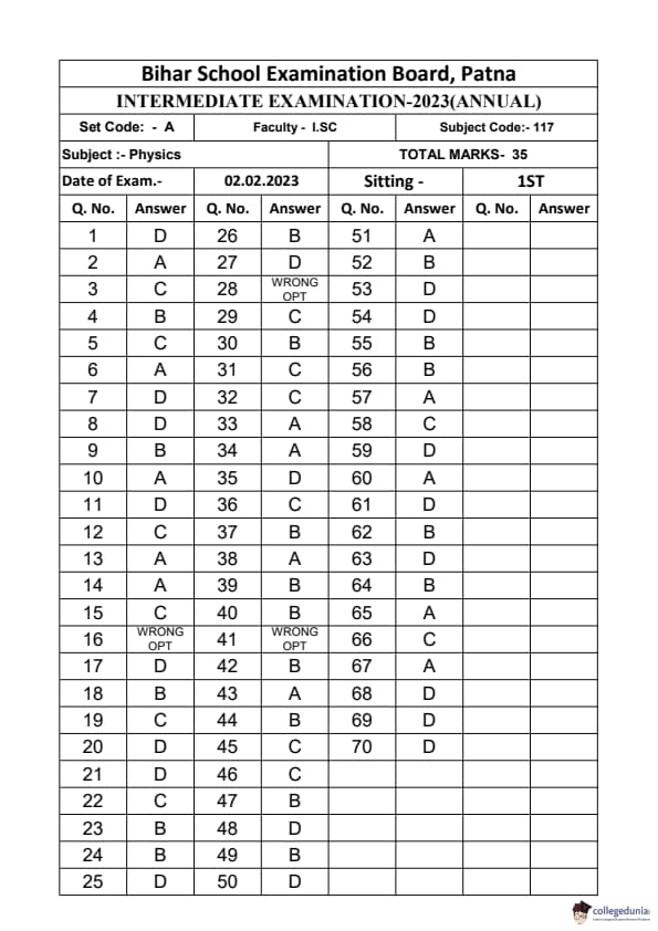
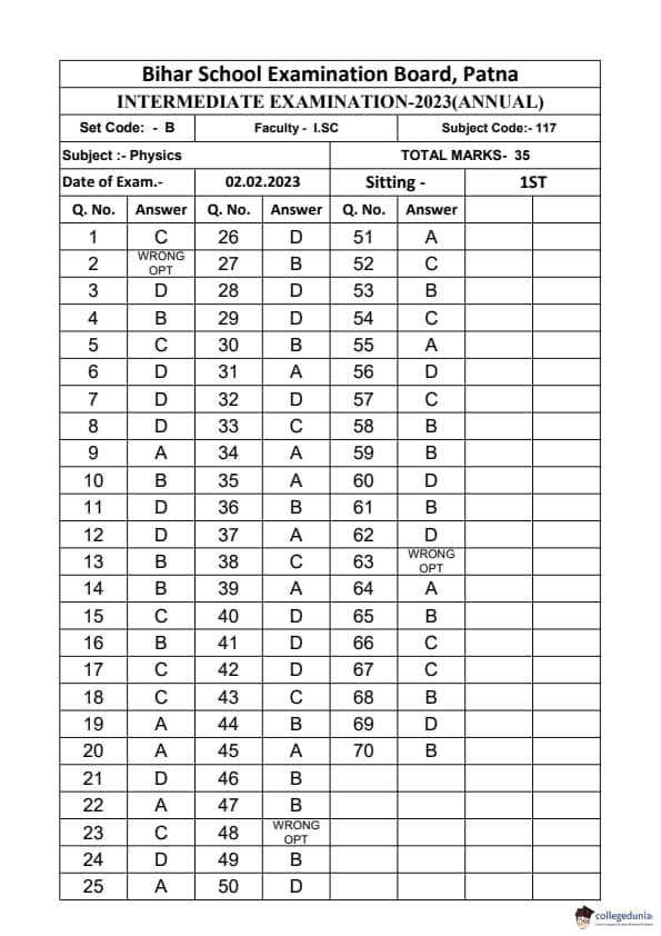
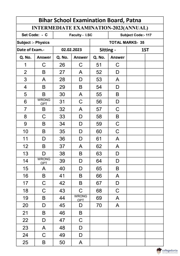
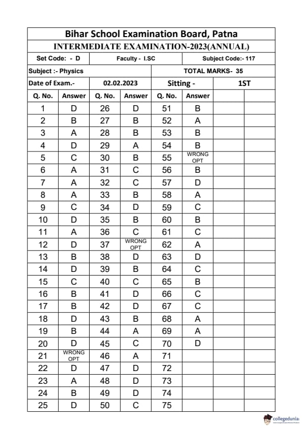

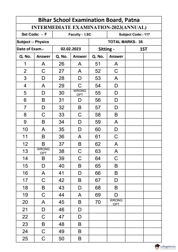

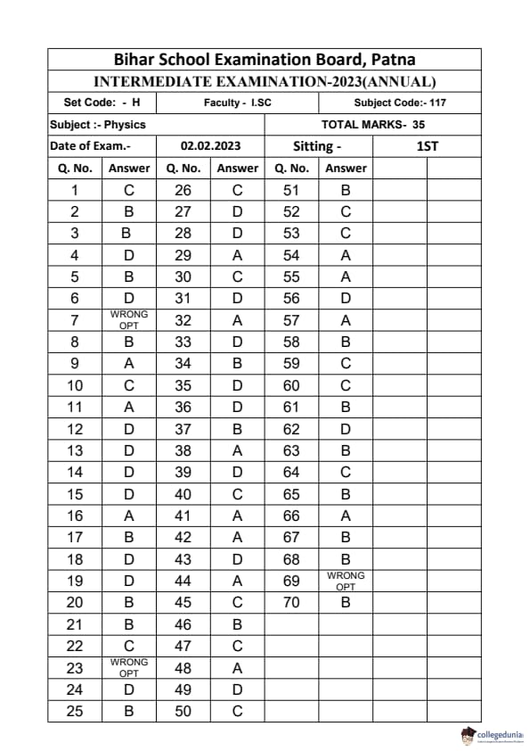
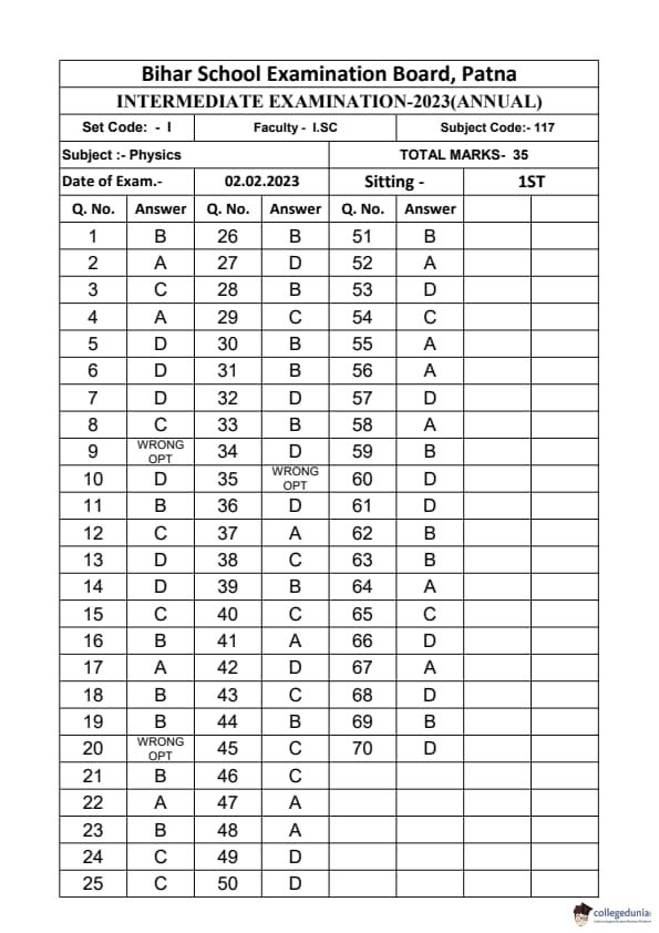
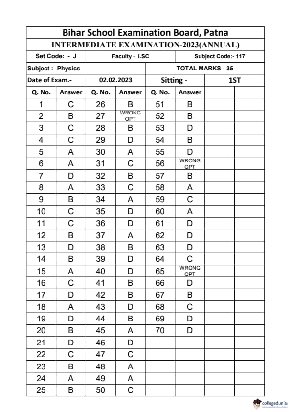
Comments