Content Curator
Pulley system makes it easier to lift heavy objects. Pulleys are made from wheels grazed by ropes. The purpose of one pulley is to change the direction of the applied force. If a fixed pulley is applied in conjunction with a movable pulley in a system, the force applied by a person is almost doubled.
Read More: Work and Energy
| Table of Content |
Key Terms: Pulley, Force, Wheels, Axle, Shaft, Power, Sheave, Fixed, Movable, Compound
What is a Pulley?
[Click Here for Sample Questions]
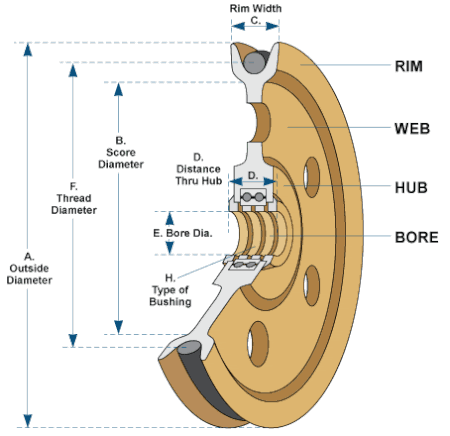
A typical pulley system uses a block (disc shaped) with ropes wrapped around it. When one applies a tension force at one end of the ropes, the other end diverts this force into a different direction. The pulley system is employed on a shaft or wheel which uses the change in direction of the cable or a taute belt. The components of a pulley sysytem are:
- Wheel
- Hook
- Flexible Belt
- Axle
Wheels on axles or shafts support the movement of pulley system. Along with transferring power between the shaft and the belt, it also changes the direction of the belt. When there is a support frame or shell to the pulley system, power isn't moved to the shaft. Using it, cables are guided and force is exerted in particular directions. Essentially, the shell acts as a block in the pulley system. This is known as a sheave.

The Pulley System
Also Check:
| Important Topics Related to Pulleys | ||
|---|---|---|
| Types of Energy | Energy and its Classification | Conservation of Energy Formula |
| Types of Springs | Simple Machines | Work Done by a Constant Force |
Mechanism of Pulley System
[Click Here for Previous Year Questions]
Pulley is one of the key tools of the trade as it helps lift heavy loads with minimal effort. Because it is a unique mechanism, it has become one of the most important tools. In industries, it is used in different kinds of machines. Although pulley system makes it easy to lift heavy loads, sometimes, mechanism of pulley system gets complex.
- It is a wheel built on an axle.
- A central shaft rotates the wheel or the gear and allows the movement of the cable or belt.
- The power between the axle or the shaft is transferred to the cable or the belt.
- Grooves which are long and have a narrow indentation allow the material to move.
Also Read: Potential Energy of a Spring
Types of Pulleys
[Click Here for Sample Questions]
The different types of pulley systems work on different mechanisms. The broad classification of pulley systems are:
- Fixed
- Movable
- Compound
Let us look at each of these in detail.
Fixed Pulleys
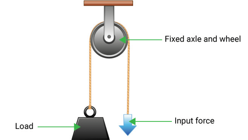
Unlike the most complex pulley systems, this type of system contains a wheel that cannot move and rotate. There is exactly the same amount of force applied to a pulley system as there is weight on it. Pulley systems with the simplest mechanism as this one are the ones that require very little space to operate.

Fixed Pulley System
Movable Pulleys
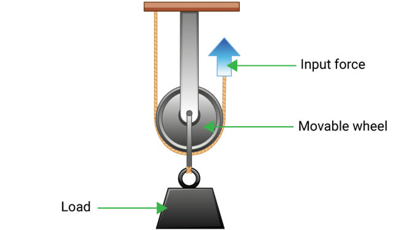
Although this pulley also has a simple wheel, the wheel can move and rotate in both directions. Compared with the weight of the object, the weight of the pulley system uses less force to lift it. This pulley system is controlled by a wheel that facilitates motion. Thus, movable pulleys are very common and are used in almost all kinds of pulley systems.

Movable Pulley System
Pulleys with Compound Shafts
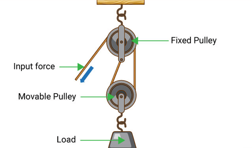
In the production of a compound pulley, a fixed pulley and a movable pulley are combined. The mechanism was designed to make it easier to carry by reducing the effort to less than half the weight of the load. Whenever heavy objects made of steel or concrete are being lifted at construction sites, pulley systems are mostly employed by cranes.

Pulleys with Compound Shaft
Pulleys for Blocking and Tackling
In block and tackle systems, two or more pulleys are attached with a rope or cable to lift heavy loads, which is used to move blocks. Assembled pulleys make up the block system in which the pulleys are connected. A pair of blocks are then arranged so one pulley remains fixed while the other is always moving.

Pulleys for Blocking and Tackling
Applications of Pulley System
[Click Here for Previous Year Questions]
Pulleys are effective in reducing the amount of force that must be exerted when lifting bodies. An example would be the application of force F to a mass hanging from the pulley.
- Normally, in order to lift such a large mass, a more powerful force is needed than the force F that was applied to the pulley system.
- By using mg, force can be represented as mass multiplied by gravity. In addition to being lifted by a pulley, this mass can also be lifted with a force of mg and tension (t) as well.
- There is tension in both the rope that is fixed to the ceiling, T, and the rope in your hand, F.
- This means that the force is distributed in two directions: to the ceiling and to your hand.
- In this case, two forces F and T are pulling the mass (m) upward.
- As mg is equivalent to F + T, we know it equals 2F = mg or F = mg/2.
- As a result, it is reasonable to assume that half the force is needed to lift a lot of weight.
- An example of this would be to use a pulley which is a simple machine.
Things to Remember
[Click Here for Sample Questions]
- Pulley Formula: Pulley formulas can be divided into the following types:
- Load/Effort- Mechanical advantage
- Velocity ratio- This refers to the ratio of the distance covered by the effort and the distance covered by the load
- Velocity ratio = distance (effort)/distance (load).
- Pulleys fall into three basic types: fixed, movable, and compound.
- When it comes to a pulley, velocity ratio refers to the ratio between distance traversed by the effort and distance traversed by the load.
Also Check:
| Important Topics From Work, Energy and Power | ||
|---|---|---|
| Kinetic Energy | Kinetic Energy Derivation | Work Energy Theorem |
| Power Vs Energy | Heat | Horse Power Formula |
| Energy Types | Force Vs Power | Linear Momentum Formula |
Previous Year Questions
- A ball is dropped from a height of 5 m on a planet where the acceleration… [NEET 1998]
- Two spheres A and B of masses m1 and m2 respectively collide… [NEET 2012]
- A shell, in flight, explodes into four unequal parts… [NEET 1998]
- A moving body of mass mm and velocity 3km/hr. Collides with a body at rest… [NEET 1996]
- Two bodies of masses m and 4m are moving with equal kinetic energies… [NEET 1998]
- How much water a pump of 2 kW can raise in one minute to a height of… [NEET 1990]
- Find the torque about the origin when a force of… [NEET 2020]
- A vertical spring with force constant k is fixed on a table… [NEET 2007]
- A particle of mass M, starting from rest, undergoes uniform acceleration… [NEET 2010]
- A force F acting on an object varies with distance x as shown in the figure… [NEET 2005]
- Water falls from a height of 60 m at the rate of 15 kg/s to operate a turbine… [NEET 2008]
- Two particles of masses m1, m2 move with initial velocities u1 and u2… [NEET 2015]
- On a frictionless surface, a block of mass M moving at speed v collides… [NEET 2015]
- A ball is dropped from a height of 5 m on a planet where the acceleration due to… [NEET 1998]
- The potential energy of a particle in a force field is… [NEET 2012]
- A batsman hits back a ball straight in the direction of the bowler without… [NEET 1989]
- Two masses of 1 g and 9 g are moving with equal kinetic energies… [NEET 1993]
- A ball moving with velocity 2m/s collides head on with another stationary ball… [NEET 2010]
- A particle moves from a point… [NEET 2016]
- A bullet of mass 10 g leaves a rifle at an initial velocity of 1000 m/s and strikes… [NEET 1989]
Sample Questions
Ques. A block of mass m is pulled, via a pulley, at constant velocity along a surface inclined at angle θ. The coefficient of kinetic friction is μk, between block and surface. Determine the pulling force F. (1 Mark)

Ans. mgcosθμk+mgsinθ
Ques. Two blocks of mass m and M are connected via pulley with a configuration as shown. The coefficient of static friction is μs, between block and surface. What is the maximum mass m so that no sliding occurs? (1 Mark)

Ans. maximum m = Mμs
Ques. A block of mass m is lifted at a constant velocity, via two pulleys as shown. Determine the pulling force F. Ignore the mass of the pulleys. (2 Marks)

Ans. Apply the condition of static equilibrium to the block. We have 2F−mg = 0. The term 2F comes from a force analysis in which we see that there are two segments of rope pulling equally on the block. We then solve this equation for F.
F = mg/2
Ques. On a pulley system, a bucket with mass m2 is hung between a block with mass m1. You need to determine the magnitude of the acceleration with which the bucket and block are moving and the magnitude of the tension force T through which the rope is stressed. Ignore the masses of rope and pulley systems. As the bucket moves up, the block moves down. (3 Marks)

Ans. The magnitude of the acceleration with which the block moves is:
a1= (m1- 2m2)g/ (m1+ 4m2)
The magnitude of the acceleration with which the bucket moves is:
a2=2a1=(2m1- 4m2) g / (m1+ 4m2)
The magnitude of the tension force T which affects the rope is:
T = 3m2m1g/ (m1+ 4m2)
Ques. Two blocks of mass m and M are hanging off a single pulley, as shown. Determine the acceleration of the blocks. Ignore the mass of the pulley. (3 Marks)

Ans. It is commonly used in physics classes for demonstrations as the Atwood machine.
Apply Newton's second law to the block on the left. We have Mg−T = Ma (taking the downward direction as positive). Apply Newton's second law to the block on the right. We have mg−T = -ma (the acceleration of the two blocks has opposite signs since one moves up and the other moves down). Combine these two equations and we can find an expression for the acceleration of the blocks.
a = (M−m)g/(M+m)
Ques. A block of mass m is pulled, via two pulleys as shown, at constant velocity along a surface inclined at angle θ. The coefficient of kinetic friction is μk, between block and surface. Determine the pulling force F. Ignore the mass of the pulleys. (3 Marks)

Ans. Apply the condition of static equilibrium to the block. We have 2F−mgsinθ−mgcosθμk = 0. The term 2F comes from a force analysis in which we see that there are two segments of rope pulling equally on the block. We then solve this equation for F.
F = (1/2)mg(sinθ+μkcosθ)
Ques. A block of mass M is lifted at a constant velocity, via an arrangement of pulleys as shown. Determine the pulling force F. Ignore the mass of the pulleys. (4 Marks)

Ans. Upon close inspection we see that the bottom two pulleys are held up by four segments of rope. The tension in the rope is assumed equal throughout its length (a good assumption for ropes in general since they weigh little).
Three of the four rope segments are vertical while the remaining rope segment is at a small angle with the vertical. But for ease of calculation we can treat it as being exactly vertical. Since we are ignoring the mass of the pulleys, the tension in the four rope segments must equal the weight of the mass, in order to satisfy the condition of static equilibrium.
Hence, 4F−Mg = 0.
We then solve this equation for F.
F = Mg/4
Ques. Two blocks of mass m and M are connected via pulley with a configuration as shown. The coefficient of static friction is μs, between block and surface. What is the minimum and maximum mass M so that no sliding occurs? (4 Marks)

Ans. For the maximum mass M, the block is on the verge of sliding down the incline. This means that Mgsinθ−T−Mgcosθμs = 0, where T is the tension in the rope. Since T = mg, we can calculate the maximum M from the previous equation.
For the minimum mass M, the block is on the verge of sliding up the incline. This means that Mgsinθ−T+Mgcosθμs = 0, where T = mg. We can calculate the minimum M from the previous equation.
Minimum M = m/(sinθ+cosθμs), Maximum M = m/(sinθ−cosθμs)
Ques. Two blocks of mass m and M are connected via pulley with a configuration as shown. The coefficient of static friction between the left block and the surface is μs1, and the coefficient of static friction between the right block and the surface is μs2. Formulate a mathematical inequality for the condition that no sliding occurs. There may be more than one inequality. (5 Marks)

Ans. At some angle θ1 > θmax1 block M will slide down on its own if there is no rope attached. Similarly, at some angle θ2 > θmax2 block m will slide down on its own if there is no rope attached.
It is known that θmax1 = atan(μs1) and θmax2 = atan(μs2).
If θ1 ≤ θmax1 and θ2 ≤ θmax2 then no sliding occurs. There are three more cases to consider.
Case 1:
θ1 > θmax1 and θ2 ≤ θmax2.
Apply the equilibrium equation to block M in which it is on the brink of sliding down. We have: Mgsinθ1−Mgcosθ1μs1−Tmin1 = 0, where Tmin1 corresponds to the minimum rope tension preventing block M from sliding down. For T < Tmin1 the block slides down. From this equation we get Tmin1 = Mgsinθ1−Mgcosθ1μs1. Call this equation (1).
There is no need to consider block M sliding up since it is an impossibility for θ2 ≤ θmax2 (which means block m cannot slide down which means it cannot pull block M up).
Tmin1 must be provided by the block m and must not exceed the maximum rope tension which can be resisted by block m and not be pulled up the incline. This maximum rope tension can be determined from the following equilibrium equation applied to block m: mgsinθ2+mgcosθ2μs2−Tmax2 = 0, from which Tmax2 = mgsinθ2+mgcosθ2μs2. Call this equation (2).
For no sliding Tmin1 ≤ Tmax2. Therefore, from equation (1) and (2) we have the final inequality for this case:
Msinθ1−Mcosθ1μs1 ≤ msinθ2+mcosθ2μs2
Case 2:
θ1 ≤ θmax1 and θ2 > θmax2.
This is the same as case 1, by symmetry. Hence, the final inequality for this case is:
msinθ2−mcosθ2μs2 ≤ Msinθ1+Mcosθ1μs1
Case 3:
θ1 > θmax1 and θ2 > θmax2.
The blocks will slide together in one direction or the other. To determine the direction we must first calculate the net force pulling down on each block along their respective inclines, as a result of gravity. We do this as follows:
For block M, Fnet1 = Mgsinθ1−Mgcosθ1μs1. And Fnet1 > 0 since θ1 > θmax1.
For block m, Fnet2 = mgsinθ2−mgcosθ2μs2. And Fnet2 > 0 since θ2 > θmax2.
We now have three sub-cases to consider. The final inequalities for this case will be given within these three sub-cases, as follows.
Case 3A:
If Fnet1 = Fnet2 the blocks will not slide.
Case 3B:
If Fnet1 > Fnet2, then Fnet1 ≤ mgsinθ2+mgcosθ2μs2 for no sliding. Note that Fnet1 is equal to the rope tension, and this rope tension is the minimum required to prevent block M from sliding down the incline.
Hence, for no sliding: Msinθ1−Mcosθ1μs1 ≤ msinθ2+mcosθ2μs2
Case 3C:
If Fnet2 > Fnet1, then Fnet2 ≤ Mgsinθ1+Mgcosθ1μs1 for no sliding. Note that Fnet2 is equal to the rope tension, and this rope tension is the minimum required to prevent block m from sliding down the incline.
Hence, for no sliding: msinθ2−mcosθ2μs2 ≤ Msinθ1+Mcosθ1μs1
Do Check Out:


Comments