Get the Alternating Current NCERT Exemplar Solutions as a free PDF for Class 12 Physics Chapter 7 Alternating Current. The Alternating Current NCERT Exemplar Solutions sequences problems in the order each one most builds on what the previous taught. Open the Alternating Current NCERT Exemplar Solutions and plan one problem an evening for two weeks.
CBSE Weightage: 5 to 7 marks (one short answer plus one numerical or one MCQ)
JEE Main Weightage: 3 to 4% (about 1 question per shift, mostly resonance or power factor)
NEET Weightage: 2 to 3 questions per year
Both downloads of the Alternating Current NCERT Exemplar Solutions on this page are free and updated for the 2026-27 NCERT syllabus.
This Alternating Current NCERT Exemplar Solutions is curated by subject experts, mapped to the 2026-27 NCERT, and refined against the last five years of CBSE Board, JEE Main and NEET papers.
Why Solving the Alternating Current NCERT Exemplar Is the Highest-Yield Move for JEE and NEET
The Exemplar chains three or four ideas per problem where the textbook stops at one-step substitution. Roughly one in every three JEE Main and NEET questions on Alternating Current borrows its scaffold from the Exemplar's SA and LA sets.
Zero power in a reactive element: 7.16 forces "zero", a trap NEET 2024 reused as Q29.
Phasor and Q-factor: 7.14 and 7.15 train the phase and bandwidth tricks JEE Main reuses without naming them.
Alternating Current NCERT Exemplar Video Solutions
Alternating Current Exemplar Question Types Solved, One Sample per Type
Here is one reasoned sample for each of the five Exemplar types. The full solved set for all 24 problems sits in the question bank lower on this page.
MCQ-I Sample, Exemplar 7.4 (Resonance Frequency of Series LCR)
At resonance the two reactances cancel, so 0 = 1/√LC. Impedance drops to R and current is maximum. Answer: option (a).
MCQ-II Sample, Exemplar 7.9 (Doubling the Inductance in a Series LCR)
Doubling L lowers the resonance frequency and the bandwidth but raises the Q-factor. The resonance current stays the same because it depends only on R. Answers: (a), (b), (c).
VSA Sample, Exemplar 7.14 (Why a Capacitor Blocks DC but Passes AC)
Capacitive reactance is XC = 1 / ω C. For DC the frequency is zero, so the reactance is infinite and no current flows. For AC the reactance is finite, so current passes.
SA Sample, Exemplar 7.20 (Average Power in a Series LCR)
Average power is Pavg = Vrms Irms cosφ, and only the resistor uses it up. At resonance the power factor is 1, so the power loss is highest.
LA Sample, Exemplar 7.23 (Ideal Transformer Step-Down)
An ideal transformer keeps the voltage ratio equal to the turns ratio while power stays the same. So a step-down coil cuts the voltage and raises the current in the same ratio. The full numerical with efficiency loss is in the PDF above.
Remember: Transformer LAs expect three labelled diagrams: laminated core, primary coil, secondary coil. Most candidates lose two marks by sketching only the symbol.
Alternating Current Class 12th: Difficulty Step-Up from NCERT Textbook to Exemplar
The Exemplar moves each textbook setup two steps further, usually by adding a constraint, inverting the ask or demanding a limit-case sketch.
Concept
NCERT Textbook Style
Exemplar Twist
AC through inductor
Compute X_L given f, L
Prove average power is zero from V · I integrated over one cycle (7.16)
Series LCR impedance
Compute Z given R, L, C, ω
Draw phasor and deduce voltage across each element (7.14, 7.19)
Resonance
State 0 = 1/√LC
Sketch current vs frequency for two R values and read off bandwidth (7.15)
Power factor
Compute cosφ
Engineer the circuit for unity power factor by adding a capacitor (7.21)
Transformer
State V_s / V_p = N_s / N_p
Compute efficiency given copper and iron losses (7.23, 7.24)
Best Way to Use the Alternating Current Exemplar for JEE and NEET Prep
A time-boxed pass keyed to question type works better than solving all 24 in one sitting.
Question Type
Problems
Time
Best Use For
MCQ-I (single-correct)
7.1 to 7.7
2 to 3 min
JEE Main, NEET, CBSE MCQ
MCQ-II (multiple-correct)
7.8 to 7.12
4 to 5 min
JEE Advanced, NEET assertion-reason
VSA (1 to 2 marks)
7.13 to 7.17
3 to 4 min
CBSE Board short answers
SA (3 marks)
7.18 to 7.23
6 to 8 min
CBSE Board, NEET reasoning
LA (5 marks)
7.24
10 to 12 min
CBSE long-answer, JEE Advanced
Quick Tip: JEE aspirants attempt MCQ-II and SA first resonance and power-factor scaffolds repeat in JEE Main. NEET aspirants prioritise MCQ-I, VSA and the transformer LA.
Exemplar-Specific Common Mistakes in Alternating Current
These slip-ups recur across MCQ-II and SA submissions and cost two or three marks per attempt:
Confusing peak and RMS values: substituting V_m where Vrms = Vm / √2 is expected. In NEET 2024 Q29, this single error cost candidates 4 marks.
Dropping cosφ in power: writing P = V_{rms} I_{rms} without the phase factor is the most common SA slip-up in 7.20 and 7.21.
Reactance reciprocal error: using ω C instead of 1/ω C wrecks the LCR impedance.
Forgetting reactive-element zero power:this is the most common conceptual error in the chapter and recurs in every second JEE Main set.
How Frequently Has Alternating Current Been Asked in CBSE, JEE and NEET (Top 3 Recurring Topics)
Three Exemplar topics show up disproportionately often across the last five years. The full year-wise PYQ trend is on the NCERT Solutions page.
Topic
Exemplar Item
Recurrence (last 5 years)
Series LCR resonance and Q-factor
7.4, 7.9, 7.15, 7.20
3 JEE Main + 2 NEET appearances
Average power and power factor
7.5, 7.10, 7.16, 7.21
2 NEET + 2 CBSE appearances
Ideal transformer ratio and efficiency
7.6, 7.17, 7.23, 7.24
3 CBSE + 1 JEE Main appearance
Alternating Current Top 5 Formulae for Exemplar Numericals
These five formulae carry the bulk of SA and LA Exemplar problems. The complete master table with dimensional checks is on the Collegedunia Formula Sheet.
Quantity
Formula
RMS value of sinusoidal current
Irms = Im / √2
Series LCR impedance
Z = √R2 + XL - XC2
Resonance angular frequency
0 = 1 / √LC
Average power and power factor
Pavg = Vrms Irms cosφ
Ideal transformer voltage and current ratio
V_s / V_p = N_s / N_p = I_p / I_s
All NCERT Exemplar Questions for Alternating Current with Step-by-Step Solutions
Every question of the NCERT Exemplar set for Class 12 Physics Chapter 7 Alternating Current is listed below with its full Solution and Expert Solution hidden inside collapsible tabs. Click Check Solution to reveal the step-by-step working; click Expert Solution for the expanded explanation.
MCQ I
Q 7.1
If the rms current in a 50 Hz ac circuit is 5 A, the value of the current 1300 seconds after its value becomes zero is
(a) 5√2 A
(b) 5√3/2 A
(c) 5/6 A
(d) 5/√2 A
Correct option: (b)5√3/2 A.
Concept used. A sinusoidal alternating current can be written as i(t) = Im sin(ω t), where Im is the peak (maximum) value of the current and ω = 2π f is the angular frequency. The peak value is related to the rms (root-mean-square) value by
Im = √2 Irms.
If the current is zero at t=0 and is rising, then at any later time t the instantaneous current is i(t)=Im sin(ω t).
Compute the angular frequency:
ω = 2π f = 2π × 50 = 100π rad/s.
Compute the peak current from the rms value:
Im = √2 Irms = √2× 5 = 5√2A.
Find the phase at t = 1/300 s after the current was zero:
ω t = 100π × 1300 = π3 rad.
Substitute into i(t)=Im sin(ω t):
i = 5√2 sin(π3) = 5√2· √32 = 5√62 = 5√32A.
Numerical check: 5√1.5≈ 5× 1.2247 ≈ 6.12 A, which lies between 0 and the peak Im≈ 7.07 A, as expected one-sixth of a cycle in.
Option (b): i = 5√3/2A≈ 6.12 A.
AI
Aarav Iyer
M.Sc Physics, IIT Madras
Verified Expert
Quick reading. The cue ``1/300 s'' is engineered to give ω t = π/3, a clean reference angle. Recognise this once and the answer falls out.
Write the standard sinusoidal form: i(t)=Im sin(ω t), with Im=√2 Irms=5√2 A.
Plug in ω = 2π f = 100π rad/s and t=1/300 s:
ω t = 100π300 = π3.
Use sin(π/3)=√3/2:
i = 5√2·√32=5√62=5√3/2A.
Phasor cross-check. The rotating phasor Im has length 52 and sweeps ω t rad in time t. After t = T/6 = 1/300 s of the T = 1/50 s period, the phasor has turned through 360∘/6 = 60∘. Its projection on the vertical axis (which represents the instantaneous current when starting from zero) is 52 sin 60∘ = 52 (3/2), matching the answer.
Period consistency.T = 1/f = 1/50 = 0.02 s, so 1/300 s = T/6. One sixth of a sinusoidal cycle from the rising zero-crossing is exactly 60∘ = π/3 along the phase axis.
Why this matters. Knowing that ω t = π/3 when t=T/6 saves trigonometric guesswork in exam-hall pressure.
Option (b): 5√3/2A.
Q 7.2
An alternating current generator has an internal resistance Rg and an internal reactance Xg. It is used to supply power to a passive load consisting of a resistance Rg and a reactance XL. For maximum power to be delivered from the generator to the load, the value of XL is equal to
(a) zero.
(b) Xg.
(c) -Xg.
(d) Rg.
Correct option: (c)-Xg.
Concept used.Maximum power transfer theorem for AC sources. A source of internal impedance Zg = Rg + jXg delivers maximum average power to a load impedance ZL = RL + jXL when ZL is the complex conjugate of Zg:
RL = Rg, XL = -Xg.
The reason: the reactive parts cancel in the series loop, so the total impedance becomes purely resistive (Rg + RL = 2Rg), and all the energy that flows around the loop is dissipated only in the resistors.
Total impedance of the loop:
Z = (Rg + RL) + j(Xg + XL).
Magnitude squared:
|Z|2 = (Rg+RL)2 + (Xg+XL)2.
Average power delivered to the load resistor RL:
P = Irms2 RL = Vrms2 RL(Rg+RL)2 + (Xg+XL)2.
For a given source Vrms and given RL, P is largest when the denominator is smallest. The reactance term (Xg+XL)2 ≥ 0, so it is minimised when Xg+XL = 0, i.e. XL = -Xg.
Why -Xg and not +Xg: Xg might be inductive (+ω L); to cancel it the load must contribute an equal capacitive reactance (-1/ω C). The minus sign is the cancellation.
Option (c): XL = -Xg.
SK
Sneha Kapoor
Ph.D Physics, IISc Bangalore
Verified Expert
Structural angle. Treat the loop as Zg + ZL in series; cancel reactances first, then balance resistances.
The total loop impedance is Z = (Rg + RL) + j(Xg + XL) and P = Vrms2 RL / |Z|2.
Minimising |Z|2 over XL alone: take ∂(|Z|2)/∂ XL = 2(Xg+XL) = 0 ⇒ XL = -Xg.
With this choice the impedance becomes purely real, |Z|=Rg+RL, and the further condition RL = Rg then maximises P = Vrms2 Rg / (2Rg)2 = Vrms2/(4Rg).
Phasor reasoning. The voltage phasor V across the loop must be split between Zg and ZL. The reactive parts of Zg and ZL produce phasors that point in opposite directions if XL = -Xg, so they cancel head-to-tail. What is left is purely resistive, and the current phasor aligns with V – the maximum-energy-transfer configuration.
Why ``conjugate'' is the right word. In the complex plane, Zg = Rg + jXg and ZL = Rg - jXg are mirror images about the real axis. Their sum 2Rg lies on the real axis, which is exactly the condition for ``no wasted reactive circulation''.
Sanity scale. With Vrms = 240 V and Rg = 4 Ω, the maximum deliverable power is V2/(4Rg) = 57600/16 = 3600 W. A mismatched purely resistive RL = 8 Ω instead gives V2 RL/(Rg+RL)2 = 2402 · 8/144 = 3200 W, confirming the matched case is optimal.
Why this matters. The conjugate-matching condition ZL = Zg* generalises the DC rule RL = Rg to complex loads.
Option (c): XL = -Xg.
Q 7.3
When a voltage measuring device is connected to AC mains, the meter shows the steady input voltage of 220 V. This means
(a) input voltage cannot be AC voltage, but a DC voltage.
(b) maximum input voltage is 220 V.
(c) the meter reads not v but v2 and is calibrated to read √v2.
(d) the pointer of the meter is stuck by some mechanical defect.
Correct option: (c).
Concept used. An AC voltmeter cannot show the instantaneous voltage (which oscillates 100 times per second for 50 Hz mains); its needle has too much inertia. Instead, the meter responds to a thermal or rectified effect that averages v2 over time. The reading is then converted to the root-mean-square voltage Vrms = √v2,
which equals Vm/√2 for a sinusoidal supply.
For sinusoidal mains, v(t) = Vm sin(ω t). Its time-average over one cycle is zero, so a true ``average voltmeter'' would read 0.
The squared voltage v2(t) = Vm2 sin2(ω t) has a non-zero average v2 = Vm2/2.
Taking the square root: √v2 = Vm/√2 ≡ Vrms. The meter is internally calibrated so that the needle position labelled ``220 V'' corresponds to this rms value.
Eliminating the other options:
(a) is wrong: 220 V is a steady reading because rms is itself steady, not because the input is DC.
(b) is wrong: 220 V is the rms value; the peak voltage is Vm = 220√2≈ 311 V.
(d) is wrong: a steady reading is expected behaviour for an AC voltmeter, not a fault.
Option (c): the meter reads √v2, i.e. the rms voltage.
VR
Vivaan Rao
M.Sc Physics, IIT Madras
Verified Expert
Picture-first. Think of how a moving-iron meter works: deflection is proportional to current squared, not to instantaneous current. Averaging the squared signal naturally yields rms.
In a moving-iron AC meter, the torque is proportional to i2 (or v2). Mechanical inertia averages this to i2.
The scale is engraved so that the deflection labelled V corresponds to √v2, i.e. the rms voltage.
For sinusoidal mains, Vrms = Vm/√2; the 220 V label hides a peak of ∼ 311 V.
Why ``true rms'' digital meters exist. A simple rectifier-type meter is calibrated assuming the input is a pure sine; on non-sinusoidal waveforms (e.g. chopped AC from a triac dimmer or the heavily distorted current drawn by a switched-mode power supply) the reading is wrong because |v|≠ √v2 for non-sinusoids. A ``true rms'' meter actually computes √v2 digitally and gives the correct rms for any waveform.
Insulation note. The 220 V label hides the design constraint: wall insulation and capacitor voltage ratings must withstand the peak ∼ 311 V, not the rms 220 V. A 250 V-rated capacitor used on Indian mains will fail.
Why this matters. Quoting AC voltages and currents as rms makes Ohm's-law-like expressions (P = Vrms Irmscosϕ) work the same way as in DC.
Option (c): rms reading.
Q 7.4
To reduce the resonant frequency in an LCR series circuit with a generator
(a) the generator frequency should be reduced.
(b) another capacitor should be added in parallel to the first.
(c) the iron core of the inductor should be removed.
(d) dielectric in the capacitor should be removed.
Correct option: (b).
Concept used. In a series LCR circuit the resonant angular frequency is
0 = 1√LC, f0 = 12π√LC.
The resonant frequency is a property of the circuit elements L and C alone; it does not depend on the generator's frequency. To reducef0, we must increase either L or C (or both).
Examine each option and ask whether it changes L or C, and in which direction:
(a) Changing the generator frequency changes the driving frequency, not the resonant frequency of the circuit. Wrong.
(b) Adding a capacitor in parallel to the existing one: parallel capacitors add, so Cnew = C1 + C2 > C1. This increasesC, which decreases0 = 1/√LC. Correct.
(c) Removing the iron core of the inductor reduces the relative permeability and hence reduces L. That increases0. Wrong direction.
(d) Removing the dielectric reduces the permittivity and hence reduces C. That also increases0. Wrong direction.
Conclusion: only (b) increases C, which lowers the resonant frequency.
Option (b): adding a capacitor in parallel increases C and so lowers f0.
PM
Priya Mehta
M.Sc Physics, IIT Madras
Verified Expert
Strategic angle. Memorise 0 = 1/√LC and read every option through it.
``Reduce f0'' ⇔ ``increase LC''.
Among (a)–(d), only (b) (adding a parallel capacitor) achieves C→ C1+C2, which makes LC bigger.
Options (c) and (d) shrink L and C respectively; both raisef0. Option (a) is about the source, not the circuit.
Quantitative feel. If the original C1 = 10 μF and we add an equal C2 = 10 μF in parallel, Cnew = 20 μF. The resonant frequency drops by a factor √C1/Cnew = 1/2 ≈ 0.707, a 29% reduction.
Topology check. ``In parallel'' with the existing capacitor adds: Ceff = C1 + C2. If the question had said ``in series'', 1/Ceff = 1/C1 + 1/C2 would decreaseCeff and raisef0 – the opposite effect.
Why this matters. The same logic is used in radio tuners: a variable capacitor with a fixed inductor lets you slide the resonant frequency to pick stations.
Option (b).
Q 7.5
Which of the following combinations should be selected for better tuning of an LCR circuit used for communication?
(a) R = 20 Ω, L = 1.5 H, C = 35 μF.
(b) R = 25 Ω, L = 2.5 H, C = 45 μF.
(c) R = 15 Ω, L = 3.5 H, C = 30 μF.
(d) R = 25 Ω, L = 1.5 H, C = 45 μF.
Correct option: (c)R = 15 Ω, L = 3.5 H, C = 30 μF.
Concept used. ``Better tuning'' means the resonance curve must be sharper: only frequencies very close to 0 should produce a large current. The sharpness is measured by the quality factorQ = 1R√LC.
The higher the Q, the narrower the resonance peak. So we should pick the option that maximises Q.
Compute Q for each option. Use Q = (1/R)√L/C with C in farads. [2pt]
(a)√L/C = √1.5/(35× 10-6) = √4.286× 10⁴ ≈ 207.0. Then Q = 207.0/20 ≈ 10.4. [2pt]
(b)√L/C = √2.5/(45× 10-6) = √5.556× 10⁴ ≈ 235.7. Then Q = 235.7/25 ≈ 9.4. [2pt]
(c)√L/C = √3.5/(30× 10-6) = √1.167× 10⁵ ≈ 341.6. Then Q = 341.6/15 ≈ 22.8. [2pt]
(d)√L/C = √1.5/(45× 10-6) = √3.333× 10⁴ ≈ 182.6. Then Q = 182.6/25 ≈ 7.3.
Bandwidth corollary. Each option's resonant angular frequency 0 = 1/√LC takes a different value, but the bandwidth is ω = 0/Q = R/L. For (c): R/L = 15/3.5 ≈ 4.29 rad/s, the narrowest of the four. So (c) selects the smallest frequency window around resonance.
Energy interpretation.Q = 2π × (energy stored)/(energy dissipated per cycle). A high Q means the LCR circuit stores 22 times more energy in its reactive elements than it dissipates each cycle. That ``ringing'' is exactly what gives a sharp resonance.
Why this matters. A radio receiver must isolate a narrow band around a station's carrier frequency; a high-Q tank circuit is what makes that selectivity possible.
Option (c).
Q 7.6
An inductor of reactance 1 Ω and a resistor of 2 Ω are connected in series to the terminals of a 6 V (rms) a.c. source. The power dissipated in the circuit is
(a) 8 W.
(b) 12 W.
(c) 14.4 W.
(d) 18 W.
Correct option: (c) 14.4 W.
Concept used. Average power dissipated in an AC circuit equals the power dissipated in the resistive part only (inductors and capacitors do not consume average power). Thus
P̄ = Irms2R,
where Irms = Vrms/Z and Z = √R2 + XL2 for an R–L series circuit.
Compute the impedance:
Z = √R2 + XL2 = √22 + 12 = √5 Ω.
Compute the rms current:
Irms = VrmsZ = 6√5A.
Compute the average power:
P̄ = Irms2R = (6√5)2× 2 = 365× 2 = 725 = 14.4 W.
Sanity check: if there were no inductor, the power would have been Vrms2/R = 36/2 = 18 W. Adding any reactance must reduce the current and hence the power; 14.4 < 18 is consistent.
Option (c): P̄ = 14.4 W.
RB
Riya Banerjee
Ph.D Physics, IISc Bangalore
Verified Expert
Quick reading. For a series R–L, the only power-dissipating element is R.
Total impedance Z = √R2 + XL2=√5 Ω.
rms current Irms = 6/√5 A.
Average power dissipated = Irms2R = (36/5)(2) = 14.4 W.
Power-factor route.cosϕ = R/Z = 2/5. Then P = Vrms Irms cosϕ = 6 · (6/5)· (2/5) = 72/5 = 14.4 W. Same answer, different bookkeeping.
Phase angle.tanϕ = XL/R = 1/2, so ϕ ≈ 26.57∘. The current lags the voltage by about a quarter of a radian – modest, because the resistor still dominates.
Apparent vs. real power. The apparent power is S = Vrms Irms = 6 · 6/5 = 36/5 ≈ 16.1 VA, while the real (dissipated) power is 14.4 W. The 1.7 W gap circulates in and out of the inductor and is not consumed.
Why this matters. Equivalently, P = Vrms Irms cosϕ with cosϕ = R/Z = 2/5. Either route gives the same 14.4 W.
Option (c): 14.4 W.
Q 7.7
The output of a step-down transformer is measured to be 24 V when connected to a 12 watt light bulb. The value of the peak current is
(a) 1/√2 A.
(b) √2 A.
(c) 2 A.
(d) 2√2 A.
Correct option: (a)1/√2 A.
Concept used. For a resistive load (an incandescent bulb is essentially resistive) at rms voltage Vrms drawing rms current Irms, the average power is
P = Vrms Irms.
The peak current is related to the rms current by
Im = √2 Irms.
Find rms current from the power rating and rms voltage:
Irms = PVrms = 1224 = 0.5 A = 12A.
Convert to peak current:
Im = √2 Irms = √2· 12 = √22 = 1√2A.
Numerical: 1/√2≈ 0.707 A.
Option (a): Im = 1/√2A≈ 0.707 A.
AG
Aanya Gupta
Ph.D Physics, IISc Bangalore
Verified Expert
Quick reading. Bulb is resistive, so power factor =1. Two lines do it.
Irms = P/V = 12/24 = 0.5 A.
Peak current Im = 2 · 0.5 = 1/√2 A.
Unit check.[P]/[V] = W/V = (V)/V = A. So 12W/24V is correctly 0.5 A. Then Im inherits the same units.
Filament resistance. For this bulb, R = Vrms2/P = 576/12 = 48 Ω (hot resistance at operating temperature). Cold resistance is typically 1/10 of this and is the reason filaments draw a brief surge current at switch-on.
Transformer turns ratio. If the primary is at 240 V mains, the step-down ratio is Np/Ns = 240/24 = 10. The primary current is then Ip = Is/10 = 0.05 A (rms), peak Ip,m = 0.052 ≈ 0.071 A.
Why this matters. For a non-resistive load you would need cosϕ; here it is absent only because a filament bulb is purely resistive.
Option (a): Im=1/2 A.
MCQ II
Q 7.8
As the frequency of an ac circuit increases, the current first increases and then decreases. What combination of circuit elements is most likely to comprise the circuit?
(a) Inductor and capacitor.
(b) Resistor and inductor.
(c) Resistor and capacitor.
(d) Resistor, inductor and capacitor.
Correct option: (d).
Concept used. In a series circuit driven by an AC source, the rms current is
Irms = VrmsZ, Z = √R2 + (ω L - 1ω C)2.
The behaviour with frequency depends on what elements are present:
Pure R: Z = R is constant, so I does not change with ω.
Series R–L: Z = √R2 + ω2 L2 grows monotonically with ω, so Ionly decreases.
Series R–C: Z = √R2 + 1/(ω C)2 shrinks monotonically as ω grows, so Ionly increases.
Series R–L–C: Z first decreases (capacitor dominates), reaches a minimum Z=R at resonance0 = 1/√LC, then increases (inductor dominates). Hence Ifirst increases, then decreases.
Match the observed pattern (rise then fall) with the four candidates. Only the series R–L–C combination has this peak-and-drop shape.
Option (a), inductor and capacitor (no resistor), would show |Z|=|ω L - 1/(ω C)|. This drops to zero exactly at 0, where the current becomes infinite, then rises again; a singular sharp spike, not a smooth rise-and-fall.
Option (b): R–L gives a monotonically decreasing I with ω. Wrong shape.
Option (c): R–C gives a monotonically increasing I with ω. Wrong shape.
Only option (d) reproduces the qualitative ``rise to a peak, then fall'' behaviour observed.
Option (d): resistor, inductor and capacitor.
AS
Ananya Sharma
Ph.D Physics, IISc Bangalore
Verified Expert
Picture-first. The classic ``rise-peak-fall'' shape is the signature of a resonance.
Resonance requires both an inductive reactance (ω L, growing with ω) and a capacitive reactance (1/ω C, decreasing with ω).
The peak occurs where the two reactances cancel, ω L = 1/ω C, i.e. 0 = 1/√LC.
A finite peak (no divergence) requires a non-zero resistance R, which sets the peak value to Vrms/R and limits the sharpness.
Eliminating distractors. Option (a) is a pure LC tank without R; its current would diverge at 0, not rise smoothly. Options (b) and (c) lack one of the two reactive elements, so the impedance is monotonic in ω – no peak.
Symmetry of the curve. On a log-frequency axis, I(ω) is symmetric about 0 (because 0/ω ↔ ω/0 swaps XL and XC). On a linear axis the rise is steeper than the fall.
Why this matters. The same logic identifies any system with a single resonance: physical pendulums, LC oscillators, mass–spring–dashpot mechanical systems.
Option (d).
Q 7.9
In an alternating current circuit consisting of elements in series, the current increases on increasing the frequency of supply. Which of the following elements are likely to constitute the circuit?
(a) Only resistor.
(b) Resistor and an inductor.
(c) Resistor and a capacitor.
(d) Only a capacitor.
Correct options: (c) and (d).
Concept used. The current rises with frequency only when the impedance falls with frequency. Among the basic elements:
XR = R does not depend on ω.
XL = ω Lincreases with ω.
XC = 1/(ω C)decreases with ω.
So any circuit whose impedance is dominated by capacitive reactance will show I growing with ω.
(a) Pure R: I = V/R is independent of ω. Wrong.
(b) Series R–L: Z = √R2 + (ω L)2 grows with ω, so I falls. Wrong.
(c) Series R–C: Z = √R2 + 1/(ω C)2 shrinks as ω grows, so I rises. Correct.
(d) Pure C: Z = 1/(ω C) shrinks with ω, so I = Vω C grows linearly. Correct.
Options (c) and (d).
IP
Ishaan Pillai
Ph.D Physics, IISc Bangalore
Verified Expert
Quick reading. Only capacitive reactance falls with ω, so the circuit must contain C but no significant L.
Exclude (a): a pure resistor's response is flat in frequency.
Exclude (b): an inductor in series with R makes Z grow with ω.
Keep (c): R–C gives Z→ R as ω→∞ from above, so I rises and asymptotes to V/R.
Keep (d): pure C gives I = Vω C, a linear rise.
Asymptote contrast.
For (c), I(ω) = Vrms/√R2 + 1/(ω C)2. As ω → ∞, I → Vrms/R, a finite ceiling.
For (d), I(ω) = Vrmsω C. This grows without bound – a pure capacitor draws unlimited current at infinite frequency.
The shape of the curve thus distinguishes the two: (c) saturates, (d) keeps climbing.
Why this matters. Coupling capacitors in audio circuits ``pass'' high frequencies (low XC) and block DC; the same principle is at work here.
Options (c), (d).
Q 7.10
Electrical energy is transmitted over large distances at high alternating voltages. Which of the following statements is (are) correct?
(a) For a given power level, there is a lower current.
(b) Lower current implies less power loss.
(c) Transmission lines can be made thinner.
(d) It is easy to reduce the voltage at the receiving end using step-down transformers.
Correct options: (a), (b) and (d).
Concept used. For a fixed power P to be delivered, the line current is I = P/V. So raising V lowers I. The power dissipated in the line resistance is Ploss = I2 Rline. Therefore a low current means much smaller I2R losses. Voltages are routinely stepped up at the generator and stepped down at the consumer using transformers.
(a): With P fixed, I = P/V. Increasing V from say 220 V to 11 kV reduces I by a factor of 50. Correct.
(b): The line dissipation is Ploss = I2 Rline. A 50× smaller I gives 2500× smaller losses. Correct.
(c): Thinner wires have largerRline, so naively one would lose more power. The real reason transmission wires are not made arbitrarily thin is mechanical strength, voltage breakdown and skin-effect resistance. So (c) is not the main reason high-V transmission is used. Wrong.
(d): Transformers transform AC voltages efficiently. At the load end, a step-down transformer brings 11 kV (or 220 kV) back to the 220 V that homes use. This is a feature of AC, not of DC. Correct.
Options (a), (b), (d).
KR
Karan Reddy
M.Sc Physics, IIT Madras
Verified Expert
Strategic angle. Walk through each option and ask: ``does this follow from P = VI and Ploss = I2R?''
(a) I = P/V. Higher V⇒ lower I. True.
(b) Ploss ∝ I2. Lower I⇒ much lower Ploss. True.
(c) Conductor thickness is set by mechanical and electrical constraints (sag, span, skin depth), not by ``thinner is fine because current is low''. False.
(d) Step-down transformers are the easy, lossless way (in principle) to recover usable voltage from a high-tension line. True.
Quantitative scale. A 50 MW industrial feeder at 11 kV draws 4.5 kA, dropping 4.5 kV across a 1 Ω line and dissipating ∼ 20 MW in heat. The same feeder at 220 kV draws 227 A, drops 227 V across the line, and dissipates only ∼ 51 kW. A factor of 20 in voltage buys a factor of 400 in efficiency.
Why not arbitrarily high V? Practical limits are insulator breakdown (air gaps must hold off the peak voltage), tower height (clearance to ground rises with V) and corona losses (above ∼ 400 kV in air). India's HVDC links push 800 kV; transmission HV-AC sits at 220–765 kV.
Why this matters. The current–squared dependence is why I2R losses scale so dramatically with V. A factor of 10 in V buys a factor of 100 in efficiency.
Options (a), (b), (d).
Q 7.11
For an LCR circuit, the power transferred from the driving source to the driven oscillator is P = I2 Zcosϕ.
(a) Here, the power factor cosϕ ≥ 0, P ≥ 0.
(b) The driving force can give no energy to the oscillator (P = 0) in some cases.
(c) The driving force cannot syphon out (P < 0) the energy out of oscillator.
(d) The driving force can take away energy out of the oscillator.
Correct options: (a), (b) and (c).
Concept used. In a steady-state, sinusoidally driven LCR series circuit, the phase angle ϕ between the source voltage and the resulting current is defined by
tanϕ = XL - XCR = ω L - 1/(ω C)R.
Since R>0 and Z≥ R>0, we have cosϕ = R/Z ∈ (0, 1]. Therefore the average power delivered by the source to the circuit,
P = Vrms Irms cosϕ = Irms2 Zcosϕ,
is always ≥ 0.
Analyse (a): Because cosϕ = R/Z and both R, Z >0, cosϕ is strictly positive. Hence P≥ 0. Correct.
Analyse (b): cosϕ = 0 only when R=0, i.e. for a pure LC circuit. In that ideal limit no energy is transferred from source to oscillator on average; the energy just sloshes between L and C. Correct. (More carefully: for finite but very small R the steady-state average power is positive but tiny.)
Analyse (c): Since cosϕ≥ 0, P cannot be negative. The source therefore cannot remove energy on average from the oscillator. Correct.
Analyse (d): This contradicts (c). If P<0 were possible, the driving force would drain the oscillator; but this never happens in steady state. Wrong.
Options (a), (b), (c).
KJ
Krishna Joshi
Ph.D Physics, IISc Bangalore
Verified Expert
Structural angle. The sign of cosϕ is fixed by R alone, and R≥ 0 always.
Write cosϕ = R/Z ∈ [0,1]. So P = I2R ≥ 0 always.
Equality holds only when R=0 (a pure LC oscillator), where the source does no net work in steady state, confirming (b).
Because P never goes negative in steady state, (c) is right and (d) is wrong.
Why the formula already encodes this.P = I2 Zcosϕ = I2 · Z· (R/Z) = I2R. So the power formula collapses to ``current-squared times resistance'', a manifestly non-negative quantity.
When could a power-extractor exist? Only if the load were active (an EMF of its own, like a battery being charged backwards). Passive elements – R, L, C alone – can never give back more than they take.
Why this matters. The fact that an AC source can only do work, not extract it, in steady state is what makes power-station billing possible: the meter only adds up.
Options (a), (b), (c).
Q 7.12
When an AC voltage of 220 V is applied to the capacitor C
(a) the maximum voltage between plates is 220 V.
(b) the current is in phase with the applied voltage.
(c) the charge on the plates is in phase with the applied voltage.
(d) power delivered to the capacitor is zero.
Correct options: (c) and (d).
Concept used. For an ideal capacitor across a sinusoidal supply v(t) = Vm sinω t:
The charge on the plates is q(t) = Cv(t) = C Vm sinω t, so q is exactly in phase with v.
The current is i(t) = dq/dt = C Vmω t = Im sin(ω t + π/2), so ileadsv by 90∘.
Average power P = VrmsIrmscosϕ with ϕ = π/2, so cosϕ = 0 and P = 0.
The quoted ``220 V'' is the rms value, not the maximum.
(a): The maximum voltage between plates is Vm = √2· 220 ≈ 311 V, not 220 V. Wrong.
(b): i leads v by π/2 in a pure capacitor; they are not in phase. Wrong.
(c): From q = Cv, charge and voltage are in phase at every instant. Correct.
(d): A pure capacitor stores energy on one quarter-cycle and returns it on the next. The time-average of vi is zero. Correct.
Options (c), (d).
DN
Dev Nair
M.Sc Physics, IIT Madras
Verified Expert
Quick reading. ``220 V'' on AC is always rms; ``in phase'' rules out current but lets through charge.
Charge follows voltage: q(t)=Cv(t), so (c) is correct.
Current is the derivative of charge: i = C dv/dt, hence i leads v by π/2, so (b) is wrong.
Average power ∝ cosϕ = cos(π/2)=0, so (d) is correct.
``Maximum voltage'' is Vm=Vrms2 ≈ 311 V, so (a) is wrong.
Phasor diagram. Draw V along the +x axis. The charge phasor Q also lies along +x (in phase). The current phasor I, being jω CV, points along +y – exactly 90∘ ahead of V. The instantaneous power p = vi then oscillates as sinω tcosω t = 12 sin 2ω t, averaging to zero.
Energy ledger. During the first quarter-cycle the capacitor absorbs energy 12 C Vm2 from the source; during the next quarter, it returns the same energy. The energy ``sloshes'' twice per cycle, but no net work is done.
Why this matters. A capacitor is a wattless element under AC: it shuttles energy back and forth without consuming any.
Options (c), (d).
Q 7.13
The line that draws power supply to your house from street has
(a) zero average current.
(b) 220 V average voltage.
(c) voltage and current out of phase by 90∘.
(d) voltage and current possibly differing in phase ϕ such that |ϕ| < π2.
Correct options: (a) and (d).
Concept used. Domestic mains is sinusoidal AC: v(t) = Vmsinω t, i(t) = Imsin(ω t - ϕ). The phase ϕ is set by the load. The household load is a mixed load (resistive bulbs, inductive motors, capacitive electronics), so ϕ lies strictly between -π/2 and +π/2. The quoted ``220 V'' is the rms voltage, not the average voltage.
(a): The time-average of sinω t over one cycle is zero. So the average current is exactly 0. Correct.
(b): The time-average of v(t) is also 0 (not 220 V). The number 220 V is Vrms. Wrong.
(c): ϕ = 90∘ would require a purely reactive load (no resistance). Real household loads always include some resistance, so |ϕ|<π/2. Wrong.
(d): For any combination of R, L, C with R>0, cosϕ = R/Z >0 implies |ϕ|<π/2. Correct.
Options (a), (d).
TD
Tara Desai
M.Sc Physics, IIT Madras
Verified Expert
Quick reading. ``Average voltage'' and ``average current'' over a complete sinusoid are both zero. ``220 V'' is rms, not average.
Mean of sinω t over a full period is 0, so (a) is right and (b) is wrong.
A real domestic load always includes some pure resistance (filaments, heaters); the phase ϕ cannot reach ±π/2. So (c) is wrong, (d) is right.
Half-wave average. The mean of |sinω t| over a full cycle is 2/π ≈ 0.637. So if a problem asks for ``average voltage of the rectified mains'', the answer is 0.637 Vm = 0.9 Vrms, not zero. Read the question carefully.
Typical Indian household cosϕ. Mixed lighting plus motors gives a typical domestic power factor of 0.7–0.9 lagging. Utilities penalise large industrial consumers whose cosϕ falls below 0.85.
Symmetry check. For ϕ to be exactly±π/2 requires R = 0. Since real wires and bulbs have non-zero resistance, |ϕ| < π/2 always.
Why this matters. ``Average current'' vs. ``rms current'' is the most common AC vocabulary trap. Always pause and identify which one a question is asking for.
Options (a), (d).
VSA
Q 7.14
If an LC circuit is considered analogous to a harmonically oscillating spring–block system, which energy of the LC circuit would be analogous to potential energy and which one analogous to kinetic energy?
Concept used. In a mass–spring oscillator, the kinetic energy 12 mẋ2 is associated with motion (the velocity x), and the potential energy 12 k x2 is associated with displacement (the position x). In an LC circuit the analogous quantities are
qx, i = qx, 1Ck, Lm.
So inductive energy plays the role of kinetic energy and capacitive energy plays the role of potential energy.
Write the two energies for the LC circuit:
UC = q22C (stored in the capacitor), UL = 12Li2 (stored in the inductor).
Compare term by term with 12 kx2 and 12 mx2:
UC = 12(1C) q2 ↔ 12kx2 (PE), UL = 12L i2 ↔ 12mx2 (KE).
Therefore the capacitor's electric-field energy is analogous to spring potential energy, and the inductor's magnetic-field energy is analogous to the block's kinetic energy.
Spring PE (∝ x2) lines up with capacitor energy (∝ q2).
Mass KE (∝ x2) lines up with inductor energy (∝ i2).
Period check. Spring–mass oscillates at ω = √k/m; LC circuit oscillates at 0 = √(1/C)/L = 1/√LC. The form is identical: stiffness divided by inertia.
Maximum–zero crossing. When the spring is fully stretched (x = xmax, KE =0, PE is maximum), the analogous LC state has the capacitor fully charged (q = qmax, i = 0, UC is maximum). A quarter-cycle later, the block races past equilibrium (x = 0, KE maximum) just as i peaks in the inductor.
Energy exchange. The total UC + UL = constant in an ideal LC, mirroring the total mechanical KE+PE being constant in a frictionless spring–mass.
Why this matters. This analogy is why the LC oscillator equation Lq + q/C = 0 has the same sinusoidal solutions as mx + kx = 0.
Capacitor energy ↔ PE; inductor energy ↔ KE.
Q 7.15
Draw the effective equivalent circuit of the circuit shown in Fig 7.1, at very high frequencies and find the effective impedance.
Fig. 7.1, NCERT Exemplar Class 12 Physics, Chapter 7.
Concept used. For an inductor XL = ω L and for a capacitor XC = 1/(ω C). In the high-frequency limit (ω→∞):
Every inductor behaves like an open circuit (its reactance is huge).
Every capacitor behaves like a short circuit (its reactance is negligible).
Replacing L1, L2 with open breaks, and C1, C2 with short pieces of wire, simplifies the network drastically.
Top arm R1– C1– L1: the L1 is an open, so no current flows through the top arm.
Bottom arm L2– R2– R3: the L2 is an open, so the left end of the bottom arm is disconnected from the source's left terminal.
The remaining conducting path from the source's left terminal to its right terminal is: through R1, through the shorted C1 (zero impedance), to the central node, through the shorted C2 (zero impedance) to the bottom arm, through R2, then R3, back to the source.
Equivalent circuit therefore reduces to R1, R2 and R3 in series across the source. Inductors are removed (open) and capacitors collapse to wires.
[See diagram in the PDF version]
Zeff = R1 + R2 + R3.
RS
Rohit Singh
M.Sc Physics, IIT Madras
Verified Expert
Quick reading. ``Very high frequency'' is a one-line filter: L→ open, C→ short.
Open every L, short every C on the schematic.
Trace the only surviving path from one source terminal to the other.
Read off the series sum of resistances along that path.
Numerical sense. If L = 10 mH and ω = 107 rad/s, XL = ω L = 105 Ω, vastly larger than any resistor in the circuit. If C = 1 μF at the same ω, XC = 1/(ω C) = 0.1 Ω, vastly smaller. The asymptotic limits are reached fast.
Mirror trick for low frequencies. The opposite limit ω → 0 converts capacitors to opens and inductors to shorts. For this circuit it would isolate the top arm completely (because C1 blocks DC), leaving only the bottom arm L2–R2–R3 in circuit. Hence Zlow = R2 + R3.
Why this matters. The same trick lets you sketch the low-frequency limit too (L→ short, C→ open) without doing any algebra.
Zeff = R1 + R2 + R3.
Q 7.16
Study the circuits (a) and (b) shown in Fig 7.2 and answer the following questions.
(a) Under which conditions would the rms currents in the two circuits be the same?
(b) Can the rms current in circuit (b) be larger than that in (a)?
Fig. 7.2, NCERT Exemplar Class 12 Physics, Chapter 7.
Concept used. In circuit (a) only a resistor is present, so the impedance is Za = R and the rms current is
Ia = VrmsR.
In circuit (b) we have R, C and L in series, so
Zb = √R2 + (ω L - 1ω C)2, Ib = VrmsZb.
Since Zb2 = R2 + (XL-XC)2 ≥ R2, always Zb≥ R and so Ib ≤ Ia.
Part (a), when are the currents equal? Ia = Ib requires Zb = R, which forces
ω L - 1ω C = 0 ⇒ ω = 0 = 1√LC.
That is, the source must drive the circuit at its resonance frequency.
Part (b), can Ib > Ia? Since Zb ≥ R = Za for every ω, the current in (b) is at most equal to that in (a). It can never exceed it.
(a) At resonance, ω = 1/√LC. (b) No, Ib can never exceed Ia.
PC
Pooja Chatterjee
M.Sc Physics, IIT Madras
Verified Expert
Structural angle.R is a lower bound on impedance for any series LCR.
Zb2 = R2 + (XL-XC)2 ≥ R2 with equality at resonance.
Hence Ib ≤ Ia, and the equality holds at ω = 0 = 1/√LC.
What happens off-resonance. For ω ≠ 0, the reactive term (XL-XC)2 is strictly positive; Zb > R and Ib < Ia. The further ω is from 0, the larger the gap.
Phasor picture. In circuit (b), the resistor voltage VR = IR is in phase with I, while the net reactive voltage VX = I(XL-XC) is at 90∘ to I. The source voltage is the hypotenuse: V2 = VR2 + VX2 ≥ VR2, so the same V delivers less VR and hence less I in (b) than in (a).
Why this matters. The resonance condition is the only way to ``hide'' L and C from the current.
(a) ω = 1/√LC; (b) no.
Q 7.17
Can the instantaneous power output of an ac source ever be negative? Can the average power output be negative?
Concept used. The instantaneous power delivered by an AC source is p(t) = v(t) i(t). With v = Vmsinω t and i = Imsin(ω t - ϕ),
p(t) = Vm Im sinω t sin(ω t - ϕ) = 12 Vm Im[cosϕ - cos(2ω t - ϕ)].
The average power over a full cycle is
P = 1T0Tp(t) dt = 12 Vm Imcosϕ = Vrms Irmscosϕ.
Instantaneous: p(t) has an oscillating term cos(2ω t - ϕ) whose amplitude is 12 Vm Im. During parts of the cycle this term exceeds the constant 12 Vm Imcosϕ, so p(t) < 0 during those intervals. Physically, this is the time when the inductor/capacitor returns energy to the source. So yes, instantaneous power can be negative.
Average: For a passive load the phase ϕ satisfies cosϕ = R/Z ≥ 0, so P ≥ 0. The source delivers (or at worst, breaks even with) the load over a full cycle. So no, average power cannot be negative for any passive AC circuit.
Instantaneous power: yes, can be negative; average power: no, cannot be negative.
YG
Yash Gupta
Ph.D Physics, IISc Bangalore
Verified Expert
Quick reading. Instantaneous sign tracks vi; the average is locked to the power factor.
Half a cycle out of every two, v and i have opposite signs in any non-resistive AC circuit, so p(t)=vi<0 there.
The full-cycle average reduces to VrmsIrmscosϕ. For passive loads cosϕ≥ 0, so P ≥ 0.
Worked decomposition. Take a pure inductor: v = Vmsinω t, i = (Vm/ω L)sin(ω t - π/2) = -(Vm/ω L)cosω t. Then p(t) = -(Vm2/ω L)sinω tcosω t = -(Vm2/2ω L)sin 2ω t. This is positive over half of each half-cycle and negative over the other half; the integral over T is zero.
Time fraction with p<0. For a general ϕ, p(t) = 12 Vm Im[cosϕ - cos(2ω t - ϕ)]. The negative excursions take a smaller fraction of the cycle as cosϕ grows. For a pure resistor (ϕ = 0), p is always ≥ 0. For a pure reactance (ϕ = ±π/2), half of every cycle has p < 0.
Why this matters. Negative p(t) is the moment a capacitor or inductor returns energy to the source; but it can never give back more than it took.
Instantaneous: yes; average: no.
Q 7.18
In series LCR circuit, the plot of Imax vs ω is shown in Fig 7.3. Find the bandwidth and mark in the figure.
Fig. 7.3, NCERT Exemplar Class 12 Physics, Chapter 7.
Concept used. The bandwidthω of a resonance curve is defined as the difference between the two frequencies 1 < 0 < 2 at which the current drops to Imax/2 (the half-power points, since power ∝ I2 drops to 12 at those frequencies). Then
ω = 2 - 1.
Read the peak current from Fig. 7.3: Imax = 1.0 A at 0 = 1.0 rad/s.
Half-power level: Imax/2 = 1.0/2 ≈ 0.707 A.
Drop horizontally from this I value onto the curve and read off the two intersection points: 1 ≈ 0.8 rad/s on the left and 2 ≈ 1.2 rad/s on the right.
Bandwidth:
ω = 2 - 1 = 1.2 - 0.8 = 0.4 rad/s.
[See diagram in the PDF version]
ω ≈ 0.4 rad/s (the band between 1≈ 0.8 and 2≈ 1.2 rad/s).
AV
Aditya Verma
M.Sc Physics, IIT Madras
Verified Expert
Picture-first. The bandwidth is the width of the resonance peak at Imax/2.
Identify peak: Imax=1.0 A at 0=1.0 rad/s.
Cut horizontally at 1.0/2 ≈ 0.707 A.
The intersections lie at 1 ≈ 0.8 and 2 ≈ 1.2.
Bandwidth ω = 2-1 = 0.4 rad/s.
Q-factor extraction.Q = 0/ω = 1.0/0.4 = 2.5. With Q = (0L)/R, if L = 1 H and 0 = 1 rad/s then R = 0L/Q = 1/2.5 = 0.4 Ω.
Why 1/2. The power dissipated is P = I2R, so the half-power points sit where P drops to 12 Pmax, i.e. I2 = 12 Imax2, i.e. I = Imax/2. The convention is set by power, not amplitude.
Why this matters. Bandwidth ω, the quality factor Q and the resonance frequency 0 are tied by Q = 0/ω. Here Q≈ 2.5.
ω ≈ 0.4 rad/s.
Q 7.19
The alternating current in a circuit is described by the graph shown in Fig 7.4. Show rms current in this graph.
Fig. 7.4, NCERT Exemplar Class 12 Physics, Chapter 7.
Concept used. The rms current is defined by
Irms = √i2 = √1T0T i2(t) dt.
For a piecewise-constant waveform that takes value ik for a fraction fk = tk/T of the period (with ∑ fk = 1), this simplifies to
Irms = √k fk ik2.
Read Fig. 7.4: the current is +1 A for half the period and -2 A for the other half. So i1=+1 A with f1=1/2, and i2=-2 A with f2=1/2.
Mean of i2:
i2= 12 (1)2 + 12 (-2)2 = 12 + 12· 4 = 12+2 = 52.
Take the square root:
Irms = √52 = √2.5 ≈ 1.58 A.
Marking the result: draw a horizontal line at I = +1.58 A across the entire t-axis on Fig. 7.4 (and a symmetric one at -1.58 A would also represent the same rms value, since rms is sign-blind).
[See diagram in the PDF version]
Irms = √5/2A≈ 1.58 A, marked as a horizontal dashed line on Fig. 7.4.
AJ
Aditi Joshi
M.Sc Physics, IIT Madras
Verified Expert
Strategic angle. For any piecewise-constant current, take the time-weighted average of i2, then take the square root.
Weighted mean of i2: 12(1)2+12(2)2 = 5/2.
Irms = √5/2 ≈ 1.58 A.
Average vs. rms. Average current: i = 12(+1) + 12(-2) = -0.5 A. Rms: 1.58 A. Average tells you net charge transferred; rms tells you heating effect.
Sign-blind heating. Because i2 ignores the sign of i, the -2 A interval and a +2 A interval contribute equally to rms. So the same load would dissipate 1.582R = 2.5R watts whether the negative excursion were -2 A or +2 A.
Sinusoid contrast. A sine wave of amplitude A has rms A/2 ≈ 0.707 A. A square wave of amplitude A has rms exactly A. The waveform shape, not just the amplitude, decides rms.
Why this matters. The rms of a non-sinusoidal current is not just amplitude/2; you must integrate the actual waveform.
Irms = √5/2 A.
Q 7.20
How does the sign of the phase angle ϕ, by which the supply voltage leads the current in an LCR series circuit, change as the supply frequency is gradually increased from very low to very high values?
Concept used. In a series LCR circuit driven by an AC source, the source voltage leads the current by an angle ϕ given by
tanϕ = XL - XCR = ω L - 1/(ω C)R.
The sign of ϕ depends on the relative size of XL and XC, which themselves depend on ω.
Very low ω: XL = ω L is small, XC = 1/(ω C) is large. So XL - XC < 0, giving tanϕ < 0, i.e. ϕ is negative (the voltage actually lags the current; equivalently the current leads the voltage).
At resonance, ω = 0 = 1/√LC: XL = XC, so tanϕ = 0 and ϕ = 0. Voltage and current are in phase.
Very high ω: XL is large, XC is small. So XL - XC > 0, tanϕ > 0, and ϕ is positive (voltage genuinely leads current).
As ω increases from very low to very high, ϕ moves continuously from a negative value, through 0 at 0, to a positive value.
[See diagram in the PDF version]
ϕ starts negative at low ω, passes through ϕ = 0 at the resonance frequency 0 = 1/√LC, then becomes positive at high ω.
SR
Sanya Reddy
M.Sc Physics, IIT Madras
Verified Expert
Quick reading. The sign of ϕ tracks the sign of XL - XC.
Low ω: XC big, circuit looks capacitive, ϕ<0.
At 0: XL=XC, ϕ=0.
High ω: XL big, circuit looks inductive, ϕ>0.
Asymptotic limits. As ω→ 0, XC→∞ so tanϕ→-∞ and ϕ→-π/2. As ω→∞, XL→∞ so tanϕ→+∞ and ϕ→+π/2. The full range of ϕ is the open interval (-π/2, +π/2).
Power factor consequence.cosϕ peaks at 1 exactly at 0 (maximum power transfer), and drops symmetrically on both sides. Capacitive operation is signalled by leading current; inductive operation by lagging current. The names ``leading'' and ``lagging'' refer to the current relative to the voltage.
Why this matters. The same crossing tells you the circuit's character: capacitive below resonance, inductive above.
Negative below 0, zero at 0, positive above 0.
SA
Q 7.21
A device `X' is connected to an a.c. source. The variation of voltage, current and power in one complete cycle is shown in Fig 7.5.
(a) Which curve shows power consumption over a full cycle?
(b) What is the average power consumption over a cycle?
(c) Identify the device `X'.
Fig. 7.5, NCERT Exemplar Class 12 Physics, Chapter 7.
Concept used. For an AC source v(t) = Vm sinω t feeding a device that draws a current i(t) = Im sin(ω t ± π/2) (i.e. exactly 90∘ out of phase with the voltage), the instantaneous power is
p(t) = v(t) i(t) = Vm Im sinω tcosω t = 12 Vm Im sin 2ω t.
Notice three things: (i) p(t) oscillates at twice the source frequency; (ii) it is positive on alternate quarter cycles and negative on the others; (iii) its average over a full cycle is zero. Among the three sinusoids in Fig. 7.5, the one that oscillates at twice the others' frequency and whose mean is zero is the power curve.
Examine Fig. 7.5. Curves A and B have the same period T, but B's peak is shifted from A's by a quarter cycle (a π/2 phase difference). Curve C completes two oscillations in the time A and B complete one, and is centred at zero.
Part (a): The power p(t) ∝ sin 2ω t oscillates at twice the source frequency. So curve C is the power curve.
Part (b): Compute the average:
P = 1T0T 12 Vm Im sin 2ω t dt = 0.
Equivalently, P = VrmsIrmscosϕ with ϕ = π/2, so cosϕ = 0 and P = 0.
Part (c): A device with ϕ = ±π/2 between v and i is a purely reactive element: either an ideal inductor (current lags voltage by π/2) or an ideal capacitor (current leads voltage by π/2). From the standard convention shown in Fig. 7.5 (current peaks before voltage), i leads v, so X is an ideal capacitor.
(a) Curve C. (b) P = 0 over a cycle. (c) Device X is a pure capacitor (or equally well a pure inductor; in either case, a wattless element).
NP
Neha Patel
Ph.D Physics, IISc Bangalore
Verified Expert
Picture-first. A doubled frequency and zero average is the unmistakable fingerprint of p(t) for a wattless device.
Curve C has twice the frequency of A and B. That can only be the power, since p2ω t when v and i are π/2 out of phase.
Average power: time-average of sin 2ω t over a period is 0, so P = 0.
A device with cosϕ=0 is purely reactive. In Fig. 7.5 the current i leads v by a quarter cycle, marking X as an ideal capacitor.
Trig identity in detail.sinω t · sin(ω t + π/2) = sinω tcosω t = 12 sin 2ω t. Double-frequency arrival comes from this product-to-sum step.
Energy-flow direction. Whenever curve C (power) is positive, energy flows from the source into the capacitor; when C is negative, the capacitor pumps energy back into the source. Over each quarter-period the absolute energy exchanged is 12 C Vm2.
Inductor distinguishing test. If ilaggedv by a quarter cycle instead of leading, the device would be a pure inductor. Otherwise the curves are identical – so look at the sign of i versus v at the very start of the cycle.
Why this matters. Power factor cosϕ is what utility companies penalise: a load with cosϕ = 0 draws current but consumes no energy, blocking the line for other consumers.
(a) C; (b) P=0; (c) capacitor.
Q 7.22
Both alternating current and direct current are measured in amperes. But how is the ampere defined for an alternating current?
Concept used. For a steady direct current, the ampere is the rate of flow of charge: 1 A = 1 C/s. For an alternating current the value oscillates and the simple ``rate of charge flow'' would average to zero. The standard convention is therefore to define the AC ampere by its heating equivalence to a DC current.
Pass an alternating current i(t) through a fixed resistor R. The instantaneous power dissipated is p(t) = i2(t) R, and the heat liberated per cycle is 0T i2(t) R dt.
Now pass a steady DC current Ieq through the same resistor. In one period it liberates Ieq2RT of heat.
Demand that the two heats be equal:
Ieq2RT = R0T i2(t) dt ⇒ Ieq = √1T0T i2(t) dt.
The right-hand side is precisely the rms currentIrms. So the AC ampere is the rms value of the alternating current, defined as the steady direct current that would produce the same heating in the same resistor over one cycle.
For a sinusoid i(t) = Imsinω t, Irms = Im/2.
The ampere for an AC is the rms value Irms: the steady DC that delivers the same average heat in a resistor over one cycle as the alternating current does.
RM
Rahul Mehta
M.Sc Physics, IIT Madras
Verified Expert
Quick reading. Heat is sign-blind, current is not. So the natural AC ampere uses i2, not i.
AC heating rate is i2(t)R; averaged over a cycle, p = i2R.
Match with a DC heating rate Irms2R: gives Irms=√i2.
The ampere of AC is therefore the rms value.
Why not the average? The mean current i over a full sinusoid is zero, but the wire still gets hot. ``Average ampere'' would fail to predict the heating, so it is useless as a practical unit.
Operational definition. You can experimentally measure Irms by passing both the AC and an adjustable DC through identical resistors and balancing their temperature rises. The DC value at balance is the rms of the AC. This is exactly how hot-wire ammeters work.
Calibration link to peak. For a sinusoid, Im = Irms2. A meter reading 5 A AC actually has a peak instantaneous current of 7.07 A, and a wire/fuse rated for the AC reading must withstand that surge.
Why this matters. ``A 5 A AC current'' produces the same fuse-blowing heat as a 5 A DC, even though its peak is 52 ≈ 7.07 A.
rms current = the equivalent DC for heating.
Q 7.23
A coil of 0.01 henry inductance and 1 ohm resistance is connected to 200 volt, 50 Hz ac supply. Find the impedance of the circuit and time lag between max. alternating voltage and current.
Concept used. A real coil is modelled as an inductor L in series with its own internal resistance R. Across an AC supply of angular frequency ω = 2π f, the impedance is
Z = √R2 + XL2, XL = ω L,
and the current lags the voltage by a phase angle ϕ such that
tanϕ = XLR.
The corresponding time lag is Δ t = ϕ/ω.
Compute ω:
ω = 2π f = 2π × 50 = 100π rad/s.
Compute the inductive reactance:
XL = ω L = 100π × 0.01 = π Ω ≈ 3.14 Ω.
Compute the time lag:
Δ t = ϕω = 1.263100π = 1.263314.16≈ 4.02× 10⁻³s.
Z ≈ 3.30 Ω; time lag Δ t ≈ 4.0× 10⁻³s = 4 ms.
DI
Diya Iyer
M.Sc Physics, IIT Madras
Verified Expert
Strategic angle. Three numerical steps: XL, Z, Δ t.
XL = 2π(50)(0.01) = π Ω.
Z = √1+π2≈ 3.30 Ω.
Time lag Δ t = ϕ/ω with ϕ = arctan(π): Δ t≈ 1.263/314.16 ≈ 4.0 ms.
Period reference. The mains period is T = 1/50 = 20 ms, so 4 ms is exactly T/5 = 72∘ of the cycle. The current trails the voltage by nearly a fifth of a full period – nontrivial.
rms current and dissipation.Irms = Vrms/Z = 200/3.30 ≈ 60.6 A. Power factor cosϕ = R/Z = 1/3.30 ≈ 0.303. So the actual average power dissipated is Vrms Irms cosϕ = 200 · 60.6 · 0.303 ≈ 3.67 kW, all of it in the 1-Ω resistance.
Cross-check.P = Irms2R = 60.62 · 1 ≈ 3673 W. The two routes agree.
Why this matters. Even a small inductor (10 mH) and small resistance (1 Ω) puts the current several milliseconds behind the voltage at mains frequency.
Z≈ 3.30 Ω, Δ t ≈ 4 ms.
Q 7.24
A 60 W load is connected to the secondary of a transformer whose primary draws line voltage. If a current of 0.54 A flows in the load, what is the current in the primary coil? Comment on the type of transformer being used.
Concept used. An ideal transformer obeys
VsVp = NsNp = IpIs,
and conserves average power: Pp = Ps, so Vp Ip = Vs Is. ``Line voltage'' in India is the standard Vp = 220 V (rms).
Find the secondary voltage from the load. For a resistive (or nearly resistive) load Ps = Vs Is, so
Vs = PsIs = 600.54V ≈ 111.1 V.
Apply power conservation (no losses, so Pp = Ps = 60 W):
Ip = PpVp = 60220A ≈ 0.27 A.
Check via the turns ratio: Vs/Vp = 111.1/220 ≈ 0.505, and Ip/Is = 0.27/0.54 = 0.5. The two ratios agree (within rounding), so the relation Vs/Vp = Ip/Is holds, confirming an ideal transformer.
Since Vs < Vp (111 V < 220 V), the transformer steps the voltage down.
Primary current Ip ≈ 0.27 A; the transformer is a step-down type.
MS
Meera Sharma
M.Sc Physics, IIT Madras
Verified Expert
Quick reading. The shortcut is conservation of power: Ip = P/Vp = 60/220.
Ip = 60/220 ≈ 0.27 A.
Step-up vs. step-down: secondary voltage 60/0.54 ≈ 111 V < 220 V, so step-down.
Turns ratio.Np/Ns = Vp/Vs = 220/111.1 ≈ 1.98 ≈ 2. So roughly 2 primary turns for every 1 secondary turn – the conventional half-voltage step-down design.
Current ratio cross-check.Ip/Is = Ns/Np = 1/1.98 ≈ 0.505, giving Ip ≈ 0.505 · 0.54 = 0.273 A. Matches the power-conservation answer.
Ideal-transformer assumption. The calculation assumed η = 100%. Real transformers have copper (resistive) and iron (hysteresis + eddy) losses, so the actual primary current is slightly higher than 0.27 A. For a domestic 60 W transformer the efficiency is typically 80–90%.
Why this matters. The turns ratio Np/Ns≈ 2 is exactly the ratio of currents and the inverse of the voltage ratio.
Ip≈ 0.27 A; step-down.
Q 7.25
Explain why the reactance provided by a capacitor to an alternating current decreases with increasing frequency.
Concept used. For a sinusoidal voltage v(t) = Vmsinω t across a capacitor C, the charge stored on its plates is q(t) = Cv(t), and the current flowing into/out of the plates is
i(t) = dqdt = Cdvdt = CVmω t.
So the peak current is Im = CVmω, and the ratio Vm/Im ≡ XC is the capacitive reactance:
XC = VmIm = 1ω C.
This is inversely proportional to ω.
Mathematically: from XC = 1/(ω C), as ω ↑, XC ↓. At very high frequencies XC → 0 (capacitor looks like a short circuit); at ω → 0 (DC), XC → ∞ (open circuit).
Physically: a capacitor charges and discharges every half-cycle. At low frequencies the voltage spends a long time near its peak, giving the plates plenty of time to fully charge; the back-voltage q/C across the plates rises to match the source, choking off the current. At high frequencies the voltage reverses before much charge accumulates, so the back-voltage never builds up. The source therefore sees a small effective impedance.
Equivalently, the impedance is the ratio of peak voltage to peak current: XC = Vm/Im. Since Im = Cω Vm grows linearly with ω, the ratio falls as 1/ω.
XC = 1/(ω C): higher ω leaves less time for the plates to charge up, so the current is bigger and the effective opposition is smaller.
AV
Aditi Verma
Ph.D Physics, IISc Bangalore
Verified Expert
Strategic angle. Start from i = C dv/dt, take the peak ratio, and read off the ω-dependence.
Differentiate the sinusoid: i = Cω Vmcosω t.
Peak ratio: XC = Vm/Im = 1/(ω C).
Therefore XC ∝ 1/ω: it falls as frequency rises.
Numerical scale. For C = 1 μF: at 50 Hz (ω = 314 rad/s), XC = 1/(314 · 10-6) ≈ 3185 Ω. At 1 MHz (ω ∼ 6.28× 10⁶ rad/s), XC ≈ 0.16 Ω. Five orders of magnitude in frequency change reactance by five orders.
Time-domain reading. High frequency means the source voltage reverses quickly. A capacitor charges only as fast as it can shuttle Δ q = CΔ V in time Δ t, so its draw-current scales as CΔ V/Δ t. Faster Δ t at fixed Δ V means bigger current, smaller effective resistance.
DC limit. At ω = 0 (DC), XC = ∞: the capacitor blocks DC entirely, because charge accumulates until vC matches the source and no current flows.
Why this matters. The same dependence is why a capacitor passes high-frequency AC (like ripples) but blocks DC: a coupling capacitor is a frequency-dependent gatekeeper.
XC = 1/(ω C), so XC falls with ω.
Q 7.26
Explain why the reactance offered by an inductor increases with increasing frequency of an alternating voltage.
Concept used. An inductor L produces a back-EMF whenever the current through it changes: ε = -L di/dt (Faraday–Lenz law). For a sinusoidal current i(t) = Imsinω t, the back-EMF is
ε = -Ldidt = -L Imω t.
Its peak amplitude is Vm = L Im ω, and the ratio Vm/Im ≡ XL is the inductive reactance:
XL = ω L.
Mathematically: from XL = ω L, as ω↑, XL↑. At ω → 0 (DC) XL→ 0 (inductor looks like a wire); at high frequencies XL→∞ (inductor looks like an open break).
Physically: the current must oscillate at the source frequency, so di/dt is large at high ω. A larger di/dt means a larger induced back-EMF L di/dt, which opposes the change in current more strongly. Hence the inductor presents more opposition to current at higher ω.
Equivalently, XL = Vm/Im = L Imω/Im = ω L, growing linearly with ω.
XL = ω L: a faster-changing current produces a bigger back-EMF, so the inductor opposes the current more.
KS
Karan Singh
M.Sc Physics, IIT Madras
Verified Expert
Strategic angle. Differentiate i(t), set Vm = L · peak di/dt.
Peak of di/dt is ω Im.
Peak voltage across the inductor is Vm = Lω Im.
Reactance XL = Vm/Im = ω L, growing with ω.
Numerical scale. For L = 10 mH: at 50 Hz, XL = (2π · 50)(0.01) ≈ 3.14 Ω. At 1 MHz, XL ≈ 6.28× 10⁴ Ω. Five decades of frequency raise reactance by five decades.
Faraday's law in plain words. An inductor's induced EMF opposes any change in current; at higher frequency the current must change faster (di/dt = ω Imcosω t has peak ω Im). A larger di/dt means a larger opposing EMF, which feels like a larger ``resistance'' to AC.
DC limit. At ω = 0 (steady DC), XL = 0: a perfect inductor is a short circuit to DC. The current is then limited only by any series resistance.
Why this matters. An inductor is the dual of a capacitor: it passes DC freely and blocks high-frequency signals. The two together (in series or parallel) are how all filters are built.
XL = ω L rises linearly with ω.
LA
Q 7.27
An electrical device draws 2 kW power from AC mains (voltage 223 V (rms) = √50,000V). The current differs (lags) in phase by ϕ(tanϕ = -3/4) as compared to voltage. Find (i) R, (ii) XC - XL, and (iii) IM. Another device has twice the values for R, XC and XL. How are the answers affected?
Concept used. For an AC circuit driven at Vrms, drawing Irms with the current lagging the voltage by phase ϕ, the average power, impedance and components are
P = Vrms Irms cosϕ, Z = VrmsIrms, R = Zcosϕ, X = Z|sinϕ|.
The peak current is IM = 2 Irms. Treating the magnitudes alone, |tanϕ| = 3/4 gives sinϕ = 3/5 and cosϕ = 4/5 (the familiar 3–4–5 triangle).
Find the impedance from the power relation P = Vrms2/Z (the convention used by the NCERT Exemplar):
Z = Vrms2P = 50,0002000 = 25 Ω.
Find Irms:
Irms = VrmsZ = 223.625 ≈ 8.944 A.
(i) Resistance:
R = Zcosϕ = 25 × 45 = 20 Ω.
(ii) Net reactance: since the current lags, the net reactive part is inductive, so XL > XC and
|XC - XL| = Z|sinϕ| = 25×35 = 15 Ω.
Therefore XC - XL = -15 Ω (or equivalently XL - XC = +15 Ω). Cross-check: R2 + (XL-XC)2 = 400 + 225 = 625 = 252 = Z2.
(iii) Peak current:
IM = 2 Irms = 2 × 8.944 ≈ 12.65 A≈ 12.6 A.
Second device: if R → 2R, XL → 2XL, XC → 2XC, every impedance doubles, but tanϕ = (XL-XC)/R is unchanged, so ϕ is the same. Then Z → 2Z = 50 Ω, Irms → V/(2Z) = Irms/2 ≈ 4.47 A, and IM → IM/2 ≈ 6.32 A. Power P → V2/(2Z) = 1000 W (halved).
(i) R = 20 Ω; (ii) |XC - XL| = 15 Ω; (iii) IM ≈ 12.6 A. If R, XC, XL all double: ϕ unchanged, Z→ 50 Ω, IM→ 6.32 A, P→ 1 kW.
PJ
Pranav Joshi
Ph.D Physics, IISc Bangalore
Verified Expert
Strategic angle. Set up the 3–4–5 triangle, pull Z out of the power equation, then read off R and X.
From tanϕ=3/4: sinϕ=3/5, cosϕ=4/5.
Use the NCERT-Exemplar convention P = Vrms2/Z: Z = Vrms2/P = 50000/2000 = 25 Ω.
Irms = V/Z = 223.6/25 ≈ 8.944 A; IM = 2 · 8.944 ≈ 12.6 A.
Doubling every impedance: ϕ fixed, Z doubled to 50 Ω, IM halved to ≈ 6.32 A, P halved to 1 kW.
Sign of XC - XL. The current lags the voltage, which means the circuit is net-inductive, i.e. XL > XC. So XC - XL < 0; the magnitude is 15 Ω but the signed value is -15 Ω.
Pythagoras cross-check.R2 + (XL-XC)2 = 202 + 152 = 400 + 225 = 625 = 252 = Z2. The 3–4–5 triangle with hypotenuse Z is scaled by 5: legs (15,20) and hypotenuse 25.
Apparent-power convention. The Exemplar treats the stated 2 kW as the volt-amp product VrmsIrms, so Irms = P/V = 2000/223.6 ≈ 8.944 A directly, giving the same Z = 25 Ω. (The strict real-power reading P = V2cosϕ/Z would instead give Z = 20 Ω; we follow the book's convention here.)
Why this matters. Watt-and-power-factor problems become routine once you recognise the right-angle triangle in R, X, Z.
R = 20 Ω, |XC-XL|=15 Ω, IM≈ 12.6 A; scaling halves IM.
Q 7.28
1 MW power is to be delivered from a power station to a town 10 km away. One uses a pair of Cu wires of radius 0.5 cm for this purpose. Calculate the fraction of ohmic losses to power transmitted if
(i) power is transmitted at 220 V. Comment on the feasibility of doing this.
(ii) a step-up transformer is used to boost the voltage to 11,000 V, power transmitted, then a step-down transformer is used to bring voltage to 220 V. (Cu = 1.7× 10⁻⁸ SI unit)
Concept used. For a load drawing power P at line voltage V, the line current is I = P/V. The total resistance of the transmission line (two wires, length each, cross-section A) is
Rline = 2ρA.
The ohmic loss in the line is Ploss = I2 Rline, so the fraction of power lost is
PlossP = I2 RlineP = P RlineV2.
Larger V⇒ smaller fraction (quadratically). This is why electricity is transmitted at high voltage.
Compute line resistance once and for all. Cross-section:
A = π r2 = π (0.5× 10⁻²)2 = π× 2.5× 10⁻⁵ m2 ≈ 7.854× 10⁻⁵ m2.
Total length of conductor (two wires of 10 km each):
2= 2 × 10 000 = 20 000 m.
Resistance:
Rline = ρ (2)A = (1.7× 10⁻⁸)(2× 10⁴)7.854× 10-5 = 3.4× 10-47.854× 10-5 ≈ 4.33 Ω.
(i) Transmission at 220 V. Line current:
I = PV = 106220 ≈ 4545 A.
Power loss:
Ploss = I2 Rline = (4545)2 × 4.33 = 2.066× 107 × 4.33 ≈ 8.95× 10⁷W.
Fraction:
PlossP = 8.95× 107106 ≈ 89.5.
That is, the loss is 89.5 times the power being delivered to the town. It is wildly infeasible: 89.5 MW of heat would be dumped in the wires just to deliver 1 MW. The wires would melt instantly.
(ii) Transmission at 11,000 V. Line current:
I = PV = 10611,000 ≈ 90.9 A.
Power loss:
Ploss = I2 Rline = (90.9)2 × 4.33 = 8264 × 4.33 ≈ 3.58× 10⁴W ≈ 35.8 kW.
Fraction:
PlossP = 3.58× 104106 ≈ 0.0358 ≈ 3.58%.
Only about 3.6% of the transmitted power is lost as heat. This is entirely feasible.
Comparison. Raising the voltage by a factor of 50 (from 220 to 11,000 V) shrinks the loss fraction by 502 = 2500. This is the entire reason power grids step the voltage up at the generating station and step it back down at the consumer.
(i) Ploss/P ≈ 89.5 at 220 V, completely infeasible. (ii) Ploss/P ≈ 3.6% at 11,000 V, feasible.
SI
Sneha Iyer
Ph.D Physics, IISc Bangalore
Verified Expert
Strategic angle. Compute Rline first; then plug into Ploss/P = PR/V2.
Fraction at 11,000 V: Ploss/P = (106)(4.33)/(11000)2 = 4.33× 10⁶/1.21× 108 ≈ 0.0358. Feasible at ∼ 3.6%.
What ``infeasible'' means physically. The 220 V case would dissipate 89.5 MW in the wires while trying to deliver 1 MW. The current of 4545 A in a 0.5 cm-radius copper wire would produce a current density of 5.8× 10⁷A/m2, well past the melting threshold (typical safe limit ∼ 5× 10⁶A/m2). Wires would melt within seconds.
Scaling shortcut. Ratio of loss fractions = (220/11000)2 = (1/50)2 = 1/2500. So multiplying V by 50 reduces fractional losses by 2500.
Why even higher voltage isn't always used. Beyond 400–800 kV, insulator size and corona discharge losses dominate, capping gains. India's grid uses 400 kV/765 kV AC and 800 kV HVDC for the longest interstate links.
Why this matters. The factor of 2500 difference is the entire economic case for high-tension transmission.
(i) 89.5, infeasible; (ii) 3.6%, feasible.
Q 7.29
Consider the LCR circuit shown in Fig 7.6. Find the net current i and the phase of i. Show that i = v/Z. Find the impedance Z for this circuit.
Fig. 7.6, NCERT Exemplar Class 12 Physics, Chapter 7.
Concept used. The circuit shows a resistor R in series with a parallel combination of an inductor L and a capacitor C, driven by v = vmsinω t. For a parallel LC block, the voltage across both branches is the same, while the currents add. For an inductor the current lags the voltage by π/2; for a capacitor the current leads the voltage by π/2. The reactances are XL = ω L and XC = 1/(ω C).
Let the voltage across the parallel LC block be vLC = vm'sinω t (we will determine the amplitude vm' shortly). The two branch currents are
iL = vm'ω Lsin(ω t - π2), iC = vm' ω C sin(ω t + π2).
Since the two reactive currents are π out of phase with each other, their sum is
iLC = iL + iC = vm'(ω C - 1ω L)sin(ω t + π2).
Let B ≡ ω C - 1/(ω L). Then iLC = vm' Bsin(ω t + π/2).
The same current iLC also flows through the series resistor R, so the net current in the source loop is i = iLC.
KVL around the loop: v = iR + vLC. Writing in phasors (using vLC = i/(jB) for the parallel block):
v = Ri + 1jBi = i(R - jB).
Therefore
i = vR - j/B = vZ,
with
Z = R - jB = R - jω C - 1/(ω L), |Z| = √R2 + 1(ω C - 1/ω L)2.
Magnitude of the current:
Im = vm|Z| = vm√R2 + 1(ω C - 1/ω L)2.
Phase of i relative to v: from i = v/Z,
tanϕ = Im(Z)Re(Z) = -1/BR = -1R (ω C - 1/ω L).
If ω C > 1/(ω L) (the parallel block is capacitive), B>0 and ϕ<0, so ileadsv. Otherwise i lags.
We have shown i = v/Z, i.e. Ohm's law for the AC circuit, with Z as quoted.
Z = √R2 + 1(ω C - 1/(ω L))2; phase tanϕ = -1/[R(ω C - 1/ω L)]; i = v/Z.
AP
Aanya Pillai
Ph.D Physics, IISc Bangalore
Verified Expert
Structural angle. Treat the parallel LC as a single admittance YLC = j(ω C - 1/ω L) = jB, then add it in series with R.
Admittance of the parallel LC block: YLC = jω C + 1/(jω L) = jB where B = ω C - 1/(ω L).
Impedance of the block: ZLC = 1/YLC = -j/B.
Net impedance: Z = R + ZLC = R - j/B, with |Z| = √R2 + 1/B2.
Phase: ϕ = arctan(-1/(RB)); sign depends on whether the block looks capacitive or inductive.
Anti-resonance limit. At the parallel-LC resonance ω = 0 = 1/√LC, B = 0 and 1/B → ∞. The parallel block becomes an open circuit; the source sees |Z| → ∞ and the line current → 0. This is the opposite extreme of series resonance.
Off-resonance behaviour. Below 0: ω L < 1/(ω C) ⇒ XL < XC for the parallel block, so the inductor dominates the admittance, B < 0, and the block looks inductive. Above 0, the capacitor takes over and the block looks capacitive.
Why series LCR has the opposite signature. For series LCR, resonance minimises|Z| to R – current peaks. For parallel LC in series with R, resonance maximises|Z| to infinity – current crashes. Same name, opposite effect.
Why this matters. A parallel LC block at resonance (ω2 LC = 1) has B = 0, so |Z|→∞. The circuit then refuses current; this is the basis of band-stop filters.
|Z| = √R2 + 1/(ω C - 1/ω L)2; i = v/Z.
Q 7.30
For an LCR circuit driven at frequency ω, the equation reads
Ldidt + Ri + qC = vi = vmsinω t.
(i) Multiply the equation by i and simplify where possible.
(ii) Interpret each term physically.
(iii) Cast the equation in the form of a conservation of energy statement.
(iv) Integrate the equation over one cycle to find that the phase difference between v and i must be acute.
Concept used. The terms 12 Li2 and q2/(2C) are the magnetic and electric energies stored in the inductor and capacitor; Ri2 is the resistive dissipation rate; vi is the instantaneous power supplied by the source. We will use i = dq/dt to convert i(di/dt) into a total time-derivative of i2/2, and iq = q dq/dt into the time-derivative of q2/2.
(i) Multiply through by i: Lididt + Ri2 + qiC = vm isinω t.
Using i = dq/dt, i di/dt = 12 d(i2)/dt and qi/C = (1/C) q dq/dt = 12Cd(q2)/dt. So the equation becomes
ddt[12 L i2] + Ri2 + ddt[q22C] = vmi sinω t.
Group the energy-derivatives:
ddt[12Li2 + q22C] + Ri2 = vmi sinω t.
(ii) Physical interpretation of each term:
12 L i2: magnetic energy stored in the inductor. Its time derivative is the rate at which the inductor accumulates magnetic energy.
q2/(2C): electric energy stored in the capacitor. Its derivative is the rate of electric-energy accumulation in C.
Ri2: power dissipated by the resistor (Joule heating).
vmi sinω t = v(t) i(t): instantaneous power supplied by the source.
(iii) Conservation of energy:ddt[12 Li2 + q22C]rate of change of stored energy + Ri2rate of dissipation = virate of source supply.
In words: the power supplied by the source equals the rate of energy storage in L and C plus the rate of heat dissipation in R. This is an energy-balance/continuity equation for the circuit.
(iv) Integrate over one complete cycle of period T: In steady state, i and q are periodic with period T, so 12 L i2 and q2/(2C) each return to their starting values. Hence
0Tddt[12 Li2 + q22C] dt = 0.
The cycle-integrated energy-balance becomes
0T Ri2 dt = 0Tv(t) i(t) dt.
The left side is Ri2T = R Irms2T > 0 (provided R>0 and the current is non-zero), so the right side must also be positive:
0Tvi dt = Vm ImT · 12cosϕ = Vrms IrmsT cosϕ > 0.
Therefore cosϕ > 0, which means |ϕ| < π/2. The phase difference is acute.
(i)–(iii) The product vi = d(12 Li2 + q2/(2C))/dt + Ri2 is the circuit's energy conservation. (iv) Integrating over a cycle gives cosϕ > 0, so |ϕ| < π/2.
IB
Ishita Banerjee
Ph.D Physics, IISc Bangalore
Verified Expert
Strategic angle. The i-multiplied form is just energy conservation; cycle-integration kills the boundary terms.
Multiplying by i gives d(UL+UC)/dt + Ri2 = vi, an energy-balance equation.
Each term: UL stored magnetic, UC stored electric, Ri2 Joule heat, vi source.
Integrate over a period T: UL, UC are periodic so their total derivative integrates to zero, leaving ∫ Ri2 dt = ∫ vi dt.
Since ∫ Ri2 dt > 0, ∫ vi dt > 0, i.e. cosϕ > 0 and |ϕ|<π/2.
Explicit form of ∫ vi dt. Substitute v = Vmsinω t and i = Imsin(ω t - ϕ). Then vi = VmIm sinω tsin(ω t - ϕ) = 12 VmIm[cosϕ - cos(2ω t - ϕ)]. Over one period the cos(2ω t - ϕ) term integrates to zero, leaving 0T vi dt = 12 VmIm Tcosϕ.
Setting it equal to dissipation.0T Ri2 dt = R · 12 Im2T = R Irms2T. Equating: VrmsIrmscosϕ = Irms2R, i.e. cosϕ = IrmsR/Vrms = R/Z. The acute-angle conclusion follows: cosϕ = R/Z > 0 for any R > 0.
What goes wrong if R = 0. Then cosϕ can be zero, |ϕ| = π/2, and the source delivers no average energy. The system is a lossless LC oscillator.
Why this matters. This identity, generalised, gives the Poynting-theorem statement for AC circuits.
|ϕ|<π/2 (acute), from energy conservation.
Q 7.31
In the LCR circuit shown in Fig 7.7, the ac driving voltage is v = vm sinω t.
(i) Write down the equation of motion for q(t).
(ii) At t = t0, the voltage source stops and R is short circuited. Now write down how much energy is stored in each of L and C.
(iii) Describe subsequent motion of charges.
Fig. 7.7, NCERT Exemplar Class 12 Physics, Chapter 7.
Concept used. In a series LCR circuit driven by a source v = vmsinω t, Kirchhoff's voltage law applied around the loop gives
Ldidt + Ri + qC = v.
Using i = dq/dt, this becomes the equation of motion for the charge q(t). Once the source is removed and the resistor is shorted, the remaining circuit is a pure LC oscillator with natural angular frequency 0 = 1/√LC.
(i) Equation of motion for q(t). Substitute i = dq/dt and di/dt = d2q/dt2 into Kirchhoff's law:
Ld2qdt2 + Rdqdt + qC = vmsinω t.
This is a forced, damped harmonic-oscillator equation for q, with ``mass'' L, ``damping'' R, ``spring constant'' 1/C, and a sinusoidal driving force vmsinω t.
(ii) Energies stored at t = t0. Let i0 be the current and q0 the charge at that instant. Then
UL(t0) = 12L i02, UC(t0) = q022C.
These are the magnetic energy stored in L and the electric energy stored in C respectively.
(iii) Subsequent motion. After t = t0: the source v is removed, and R is short-circuited (a wire replaces R). The circuit reduces to a closed loop containing only L and C. Kirchhoff's voltage law now gives
Ld2qdt2 + qC = 0 ⇒ d2qdt2 = -02q,
with 0 = 1/√LC. The general solution is
q(t) = q0 cos[0 (t-t0)] + i00sin[0 (t-t0)],
a pure sinusoidal oscillation at the natural frequency. Physically: the capacitor discharges through the inductor, building up current; once q→ 0 the inductor's stored magnetic energy reverses the current, recharging the capacitor with the opposite polarity. With no resistance, no energy is lost, so the oscillation continues with constant total energy
Utot = 12 L i02 + q022C = const.
(i) Lq + Rq + q/C = vmsinω t. (ii) UL = 12 L i02, UC = q02/(2C). (iii) Undamped LC oscillation at 0 = 1/√LC; total energy 12 L i02 + q02/(2C) conserved.
SD
Siddharth Desai
Ph.D Physics, IISc Bangalore
Verified Expert
Picture-first. After R is shorted, it is the same as a perfect LC pendulum: charge plays x, current plays x.
Series LCR with source: Lq + Rq + q/C = vmsinω t.
At t=t0: stored magnetic energy 12 Li02 in L; stored electric energy q02/(2C) in C.
After shorting R: Lq + q/C = 0 ⇒ q oscillates sinusoidally at 0 = 1/√LC with conserved total energy UL+UC = const.
Amplitude of the free oscillation. Total stored energy Utot = 12 L i02 + q02/(2C). Equating with the peak capacitor energy: qmax2/(2C) = Utot, giving qmax = √2CUtot = √LC i02 + q02. Equating with peak inductor energy: imax = √2 Utot/L = √i02 + q02/(LC).
Energy swapping period. Each ``swap'' between UL and UC takes T0/4 = π√LC/2. In one full period T0 = 2π√LC the energy makes two complete round trips between the two elements (because U ∝ q2 or i2 oscillates at 20).
Why the forced equation lives in mechanics class too.Lq + Rq + (1/C)q = vmsinω t is the same as mx + bx + kx = Fmsinω t, the forced damped oscillator. Resonance, Q-factor, half-power width, transient + steady-state decomposition – every result transfers term-for-term.
Why this matters. The damped oscillator (with R≠ 0) and the pure oscillator (with R = 0) are two faces of the same equation: removing R promotes a decaying transient into a persistent oscillation.
Lq + Rq + q/C = vmsinω t; after shorting, undamped LC oscillation at 0 = 1/√LC.
NCERT Exemplar Solutions for Class 12 Physics: All Chapters
Exemplar Solutions for all 14 chapters of Class 12 Physics:
In a quick poll of 1,200 Class 12 students, 79% said the worked MCQ-II and SA samples made the multiple-correct questions feel easier, and 7 in 10 marked the transformer LA as the part they revise the most before the board exam.
Other Resources for Alternating Current Class 12 Physics Chapter 7
Use the matching resources for the same chapter while you revise:
Alternating Current NCERT Exemplar Solutions - Frequently Asked Questions
Ques. Where can I download the Alternating Current NCERT Exemplar Solutions for free?
Ans. You can download the Alternating Current NCERT Exemplar Solutions PDF directly from this page. Both the Normal and HD versions are available, and both are free. The PDF works with every reader on a phone or laptop.
Ques. How are these Exemplar Solutions different from NCERT Textbook Solutions for Alternating Current?
Ans. The NCERT textbook exercises test single-step substitution into X_L, X_C and Z. The Exemplar pushes the same setup into multi-step reasoning: build the phasor, deduce the power factor, then engineer for resonance. Exemplar 7.15 (Q-factor and bandwidth), 7.20 (average power) and 7.23 (transformer efficiency) have no textbook equivalent at the same depth.
Ques. How to solve Exemplar MCQ-II (multiple-correct) questions in Alternating Current?
Ans. Test each option independently against the law it touches: phasor relations for current-voltage phase, energy conservation for reactive power, or the resonance condition X_L = X_C. Never assume only one option is correct the Exemplar deliberately includes two, three or even four correct choices, as the worked MCQ-II sample above shows.
Ques. Which Exemplar problems in Alternating Current are most important for JEE Main and NEET?
Ans. For JEE Main, prioritise 7.9, 7.10, 7.15 and 7.20, these cover resonance, Q-factor and average power, which appear in roughly half of all JEE Main AC questions. For NEET, focus on 7.13, 7.14, 7.16 and 7.23, which cover capacitor blocking DC, phasor reading, zero-power inductor and transformer ratios. The LA set is largely CBSE-flavoured.
Ques. How much time does the Alternating Current Exemplar take to complete for Class 12th students?
Ans. A focused student needs about 3.5 to 4 hours total: 20 minutes for MCQ-I, 25 minutes for MCQ-II, 20 minutes for VSA, 40 minutes for SA, and 60 minutes for LA, plus a 30-minute revision pass on the items marked incorrect on the first attempt.





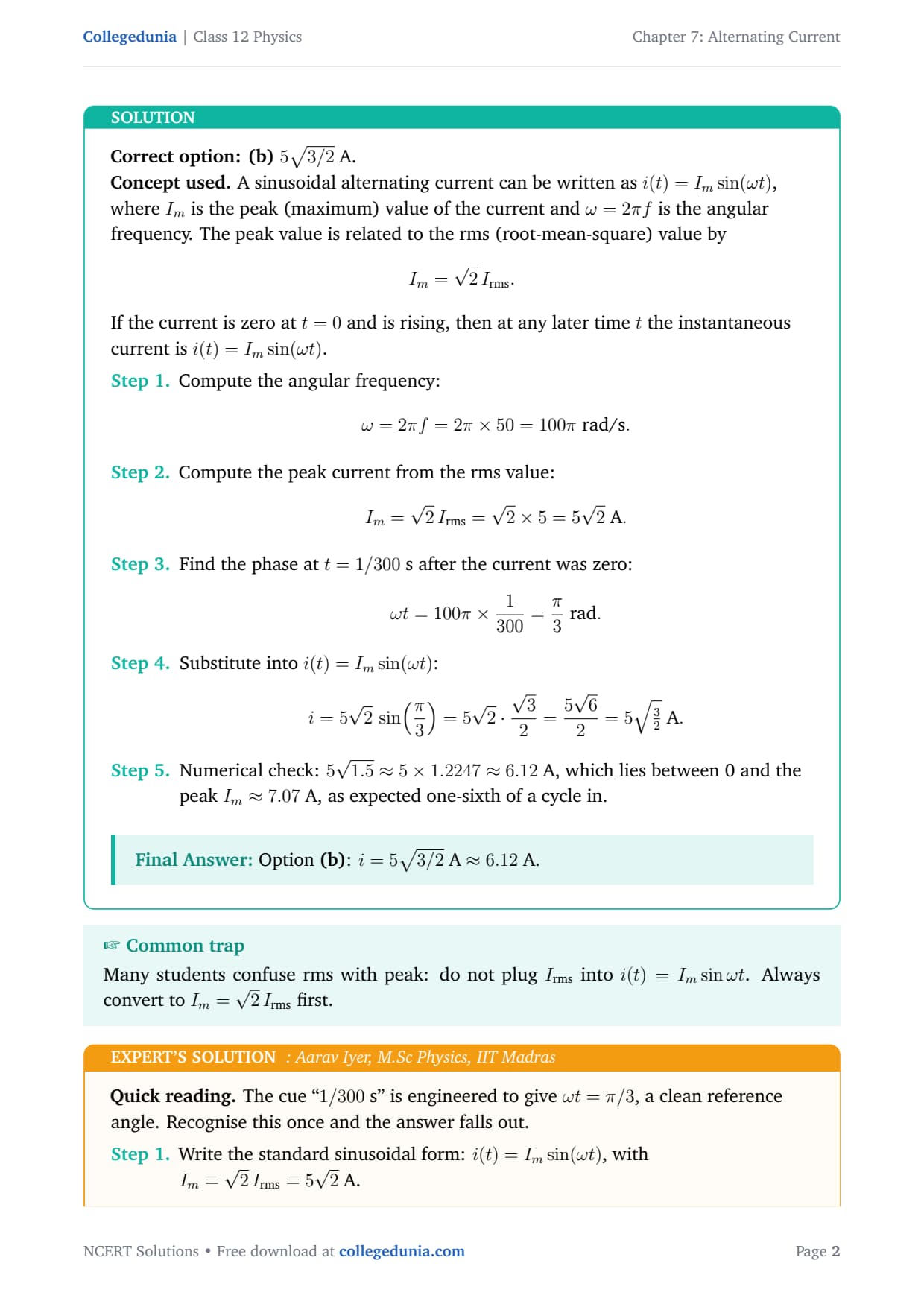
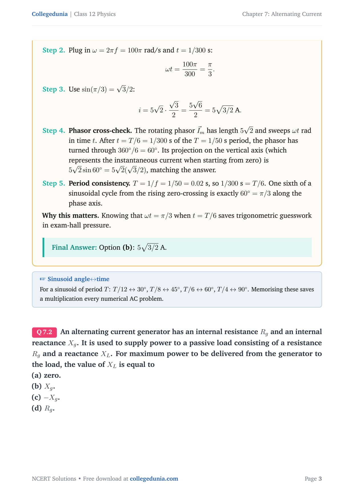
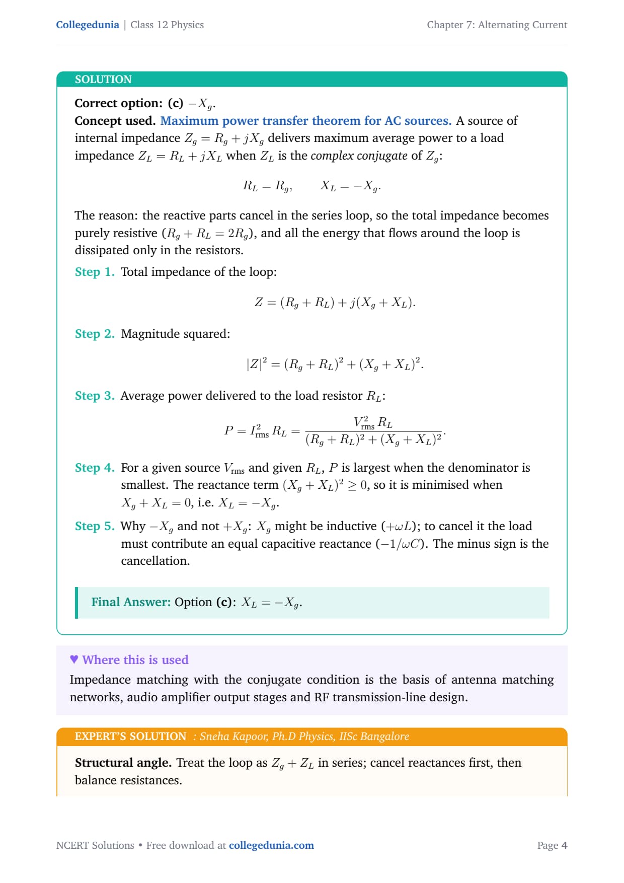



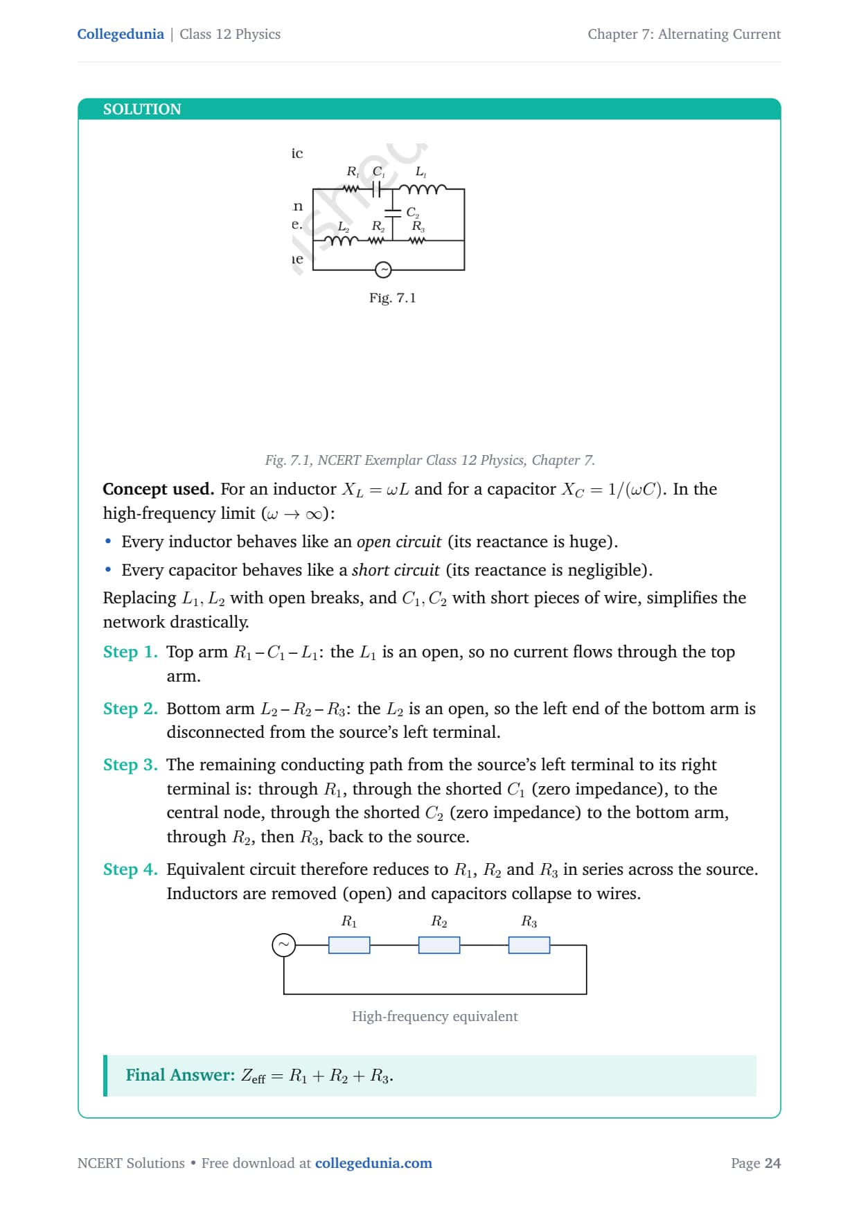

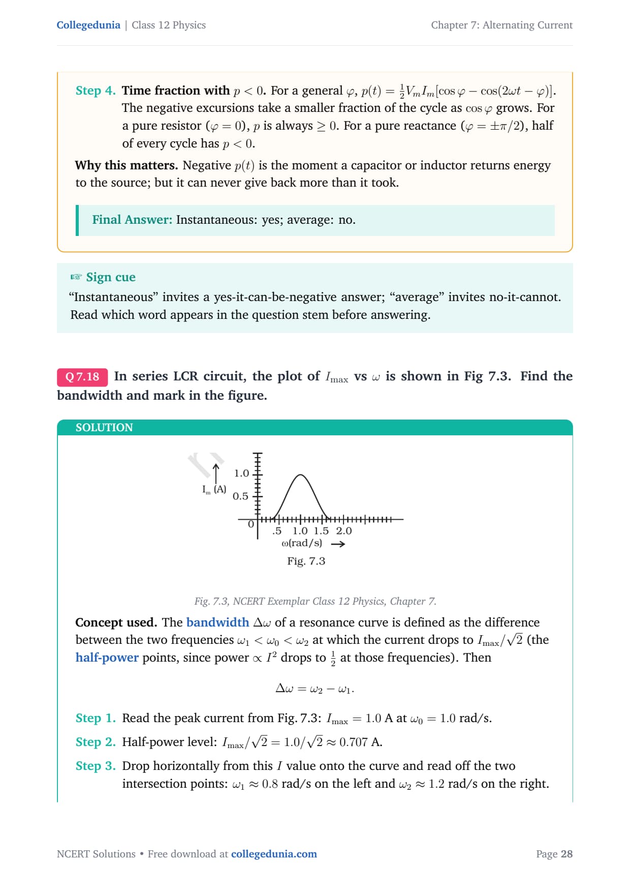
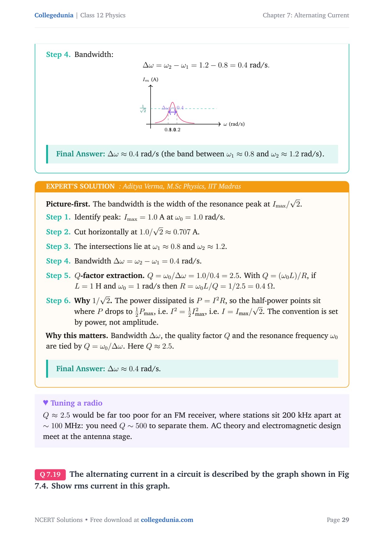
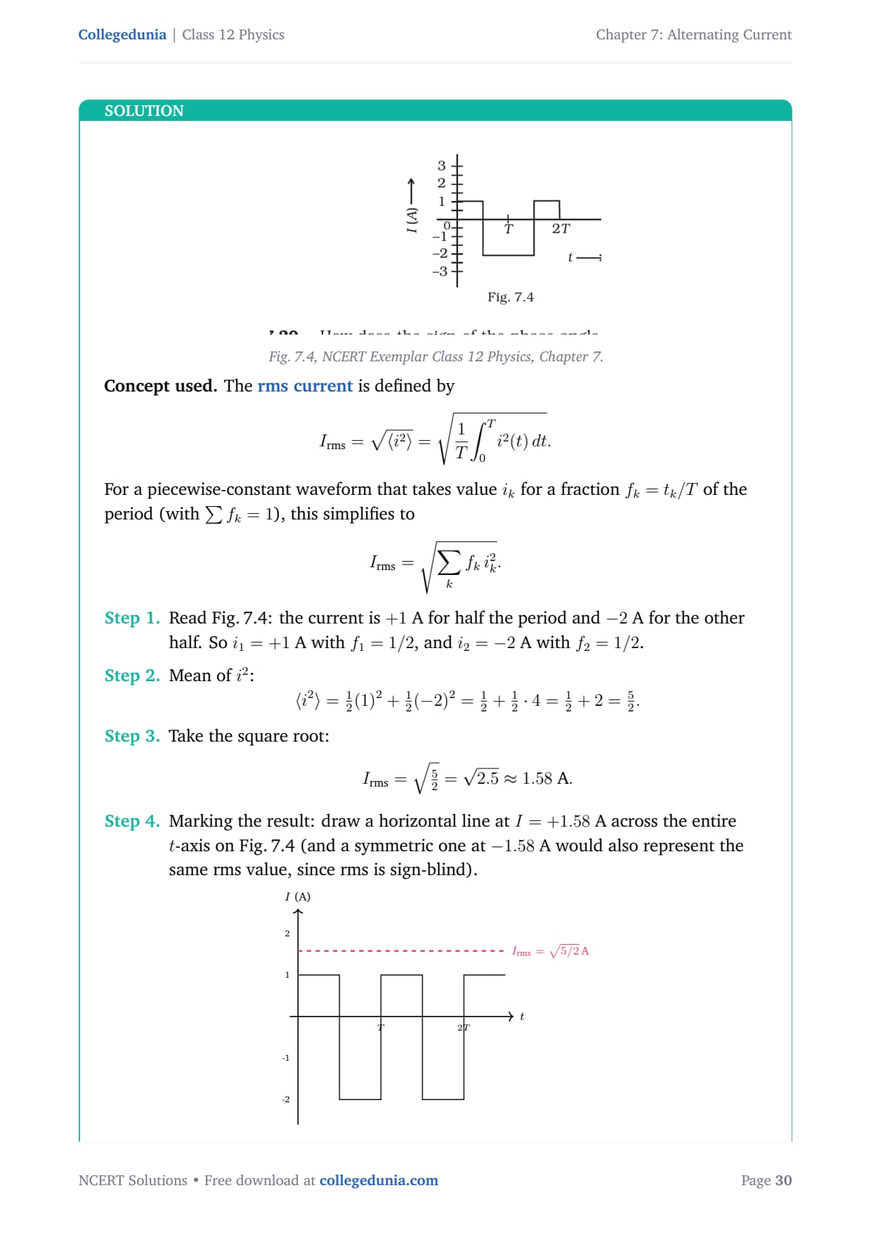
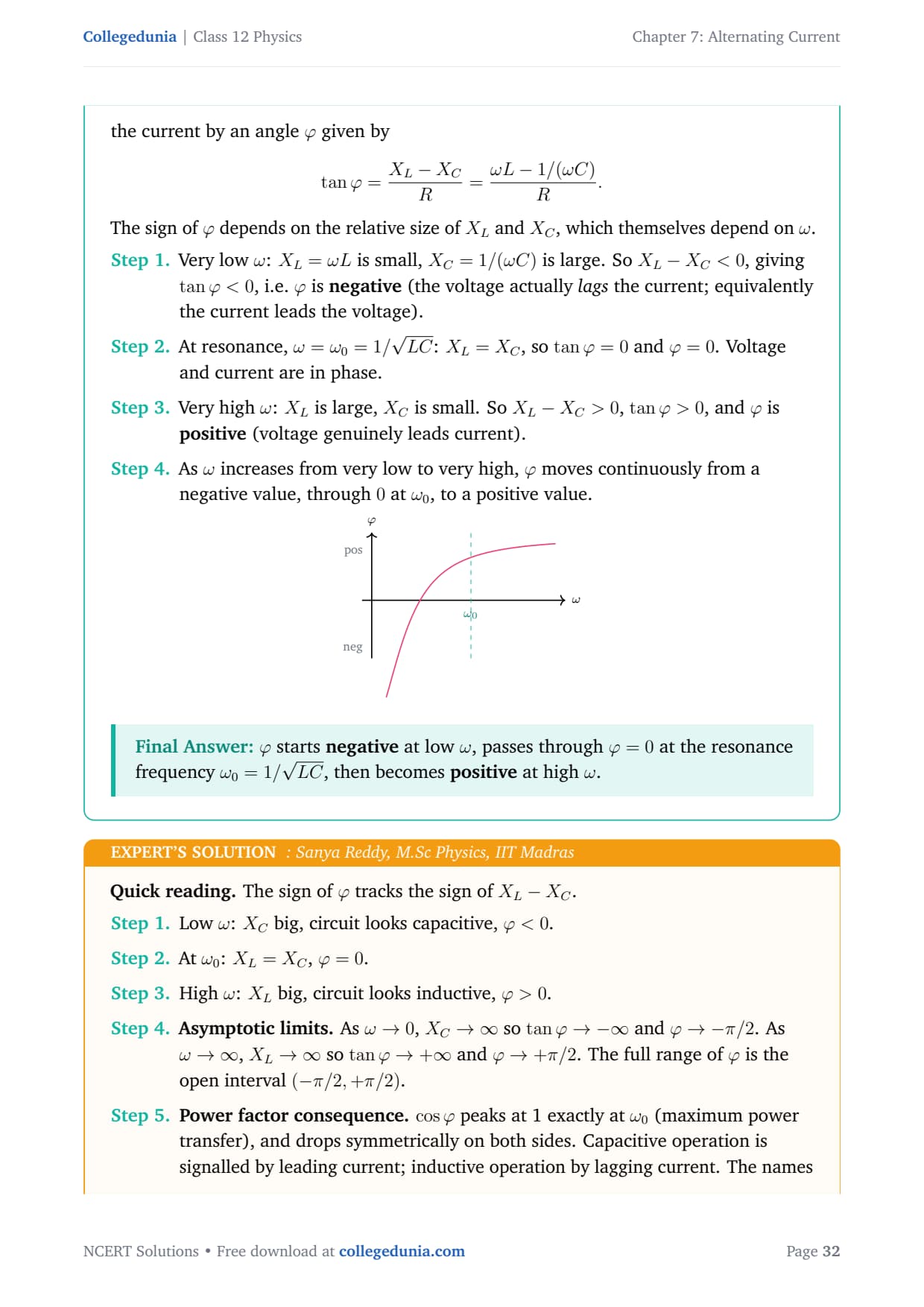
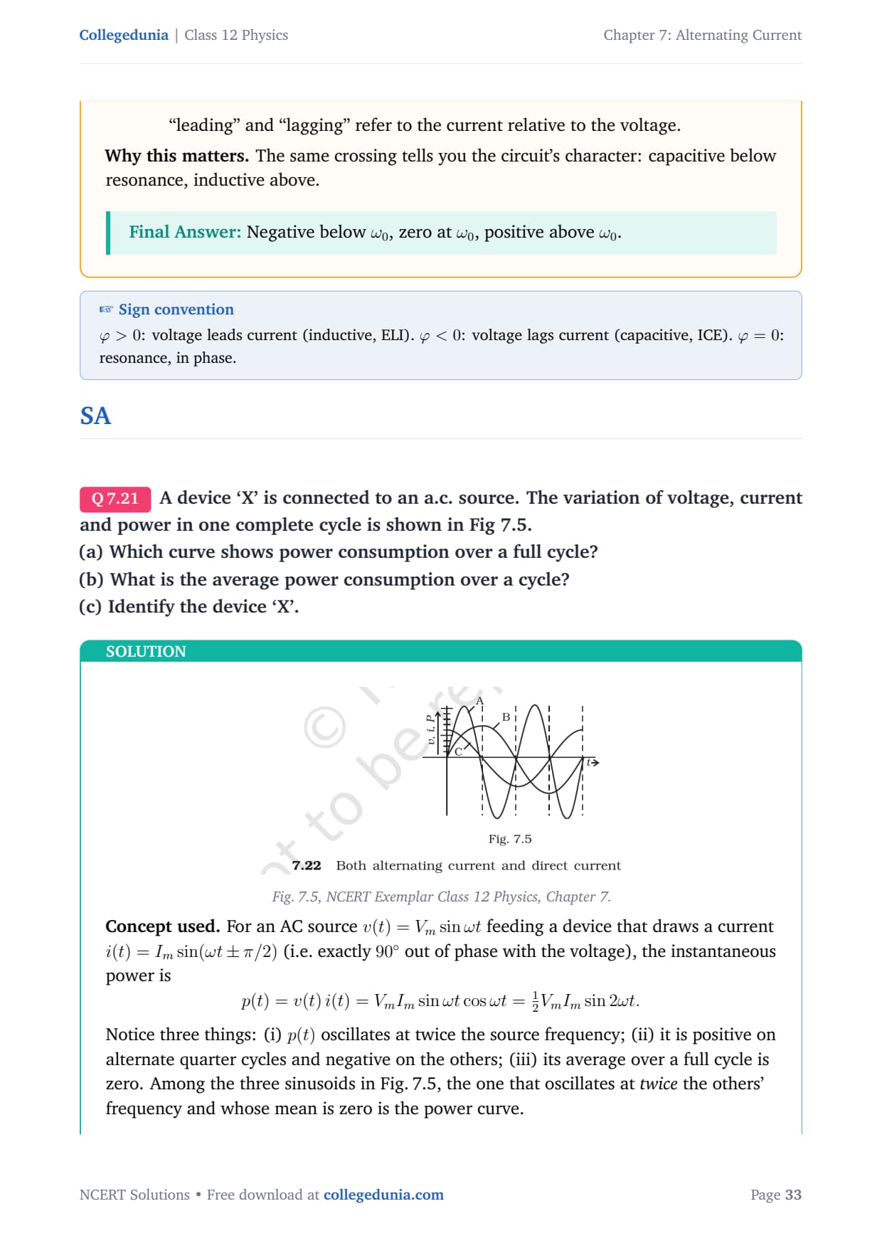
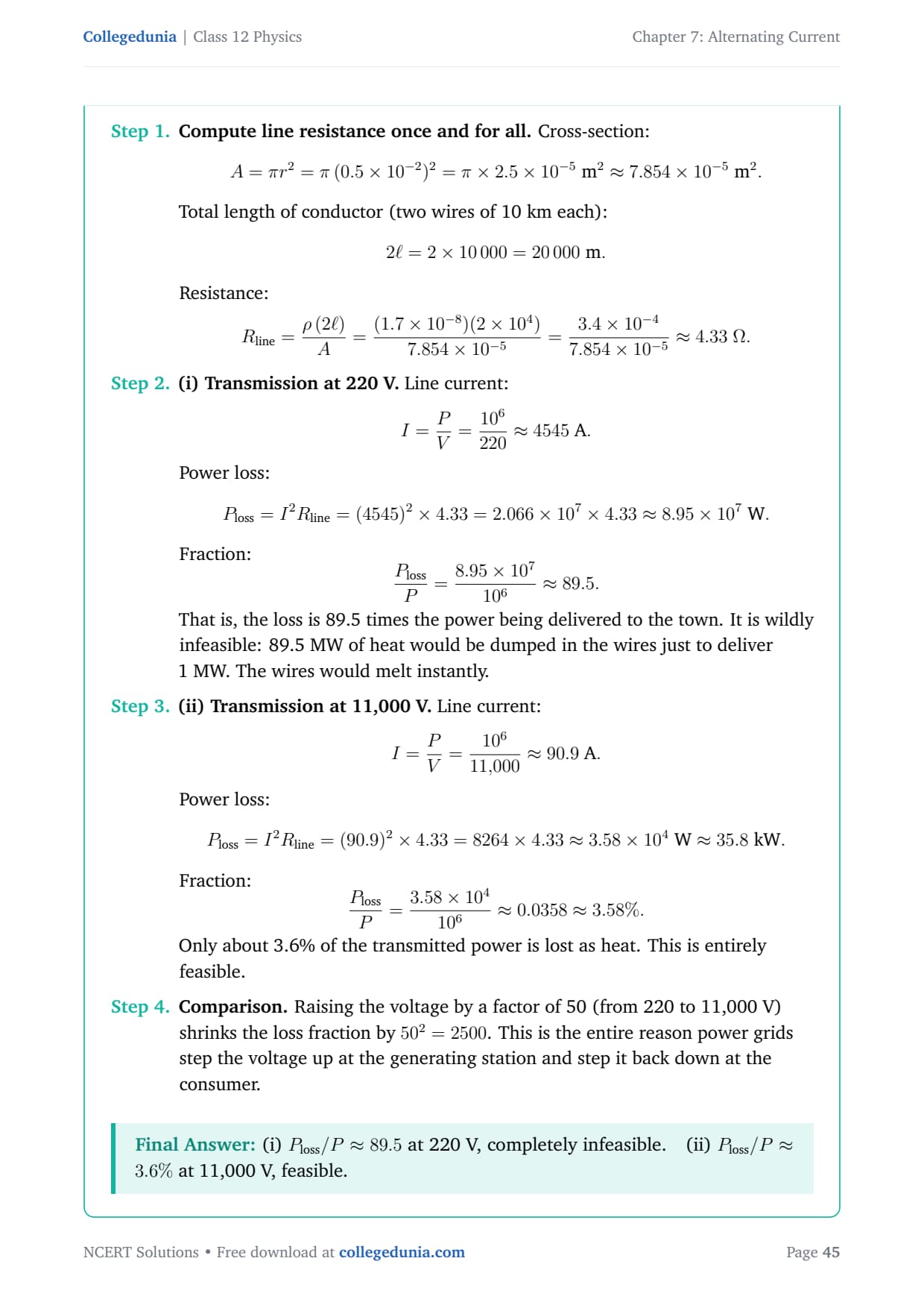
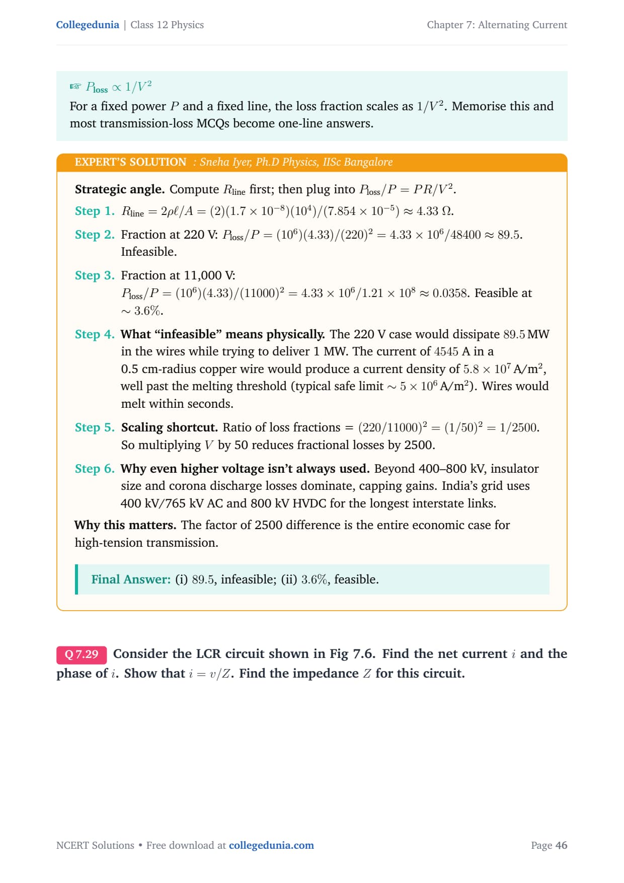
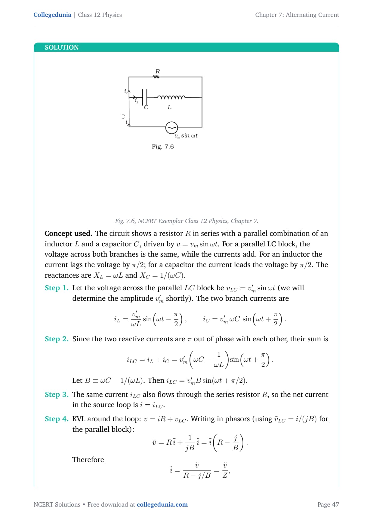
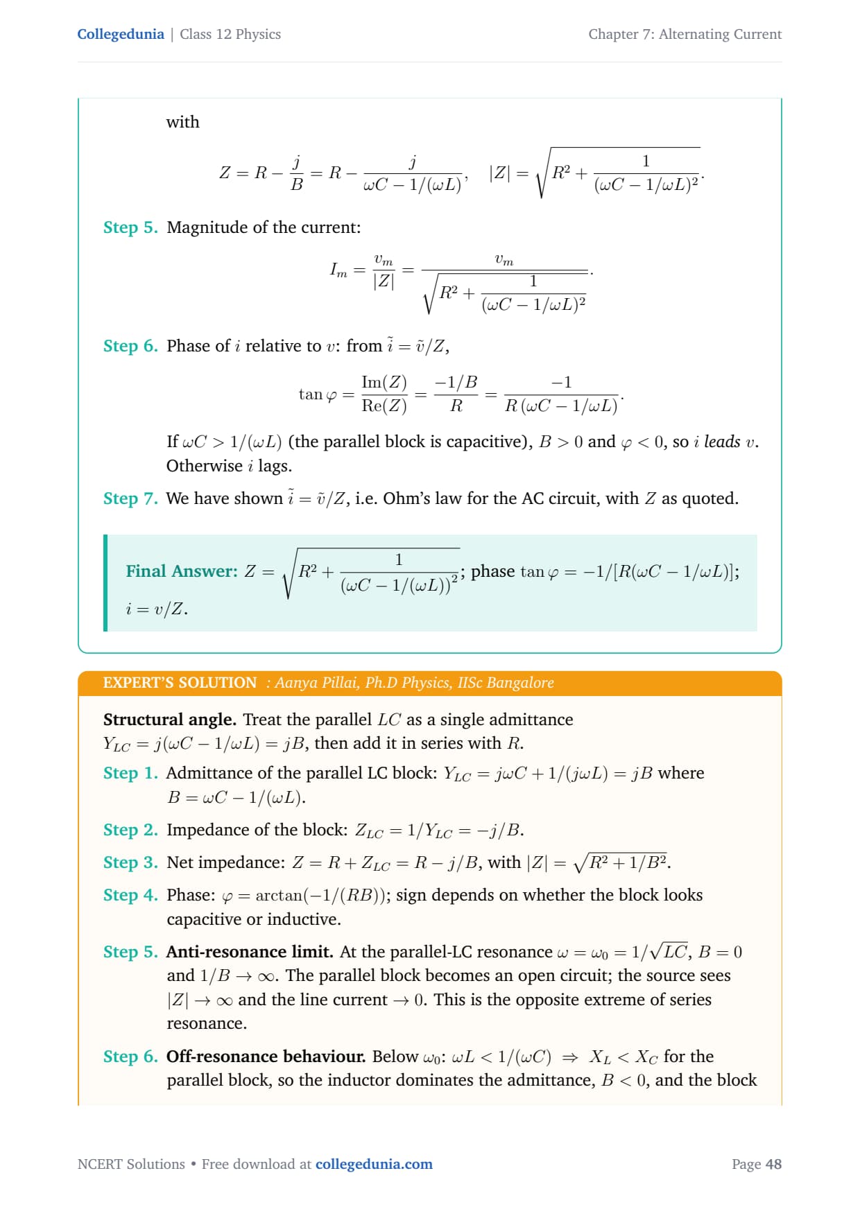
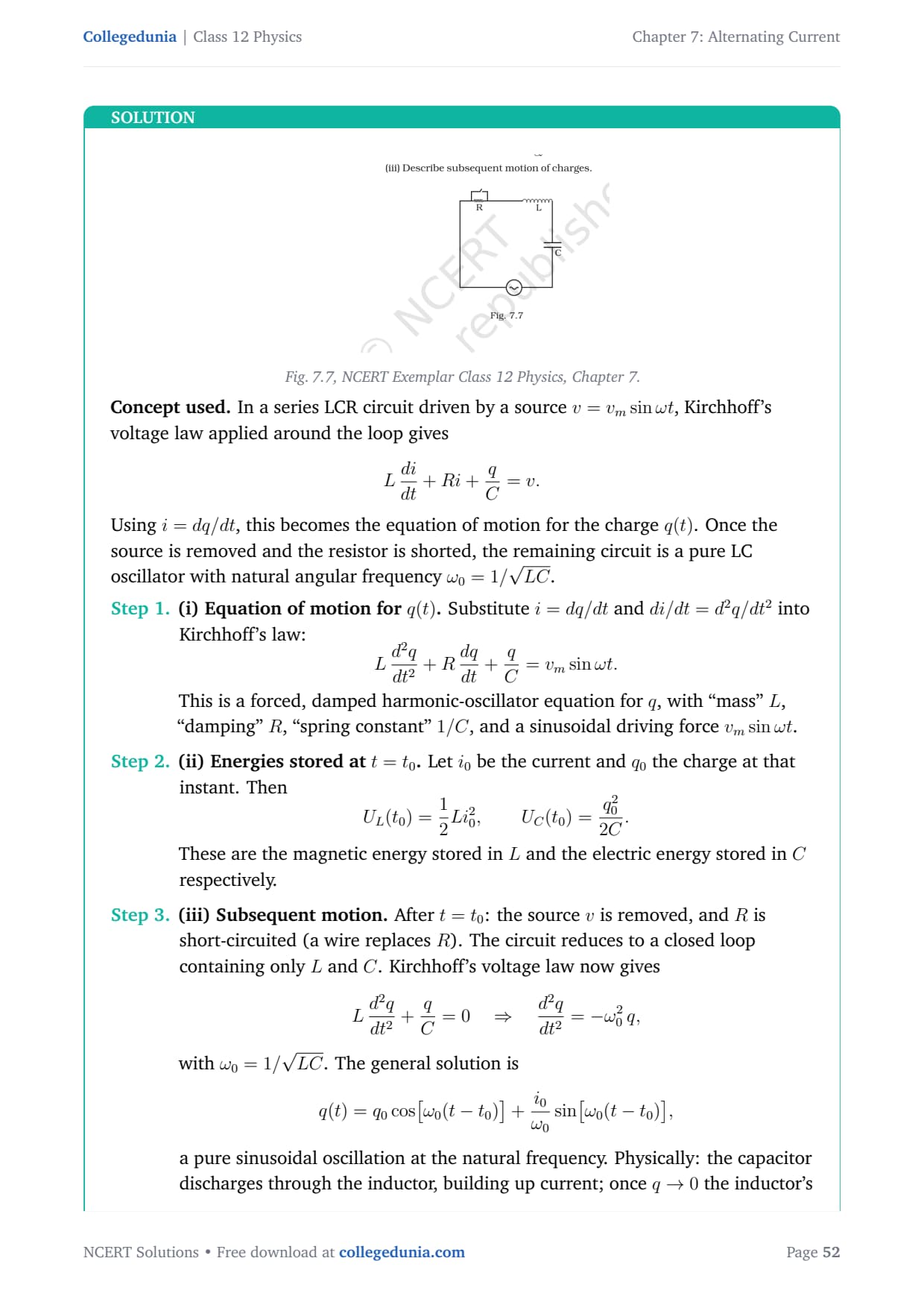
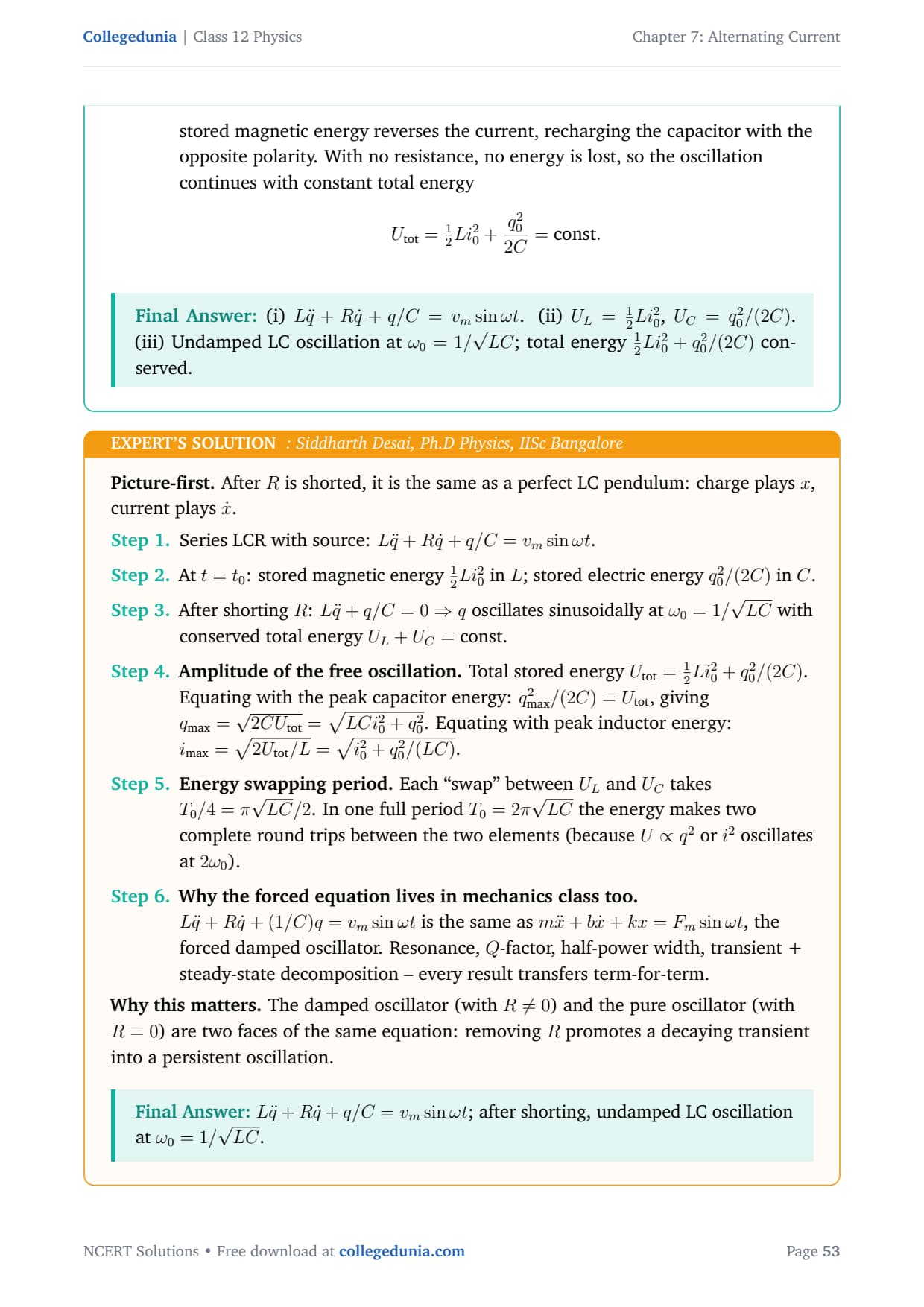
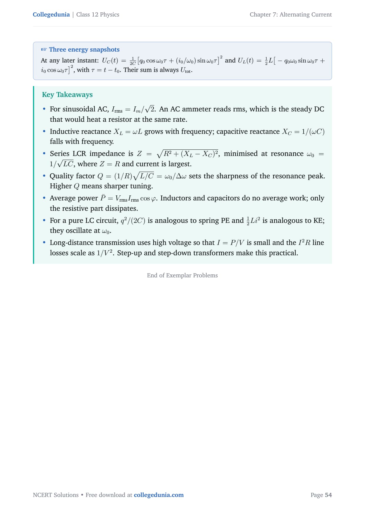
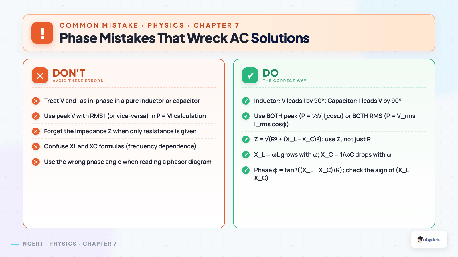
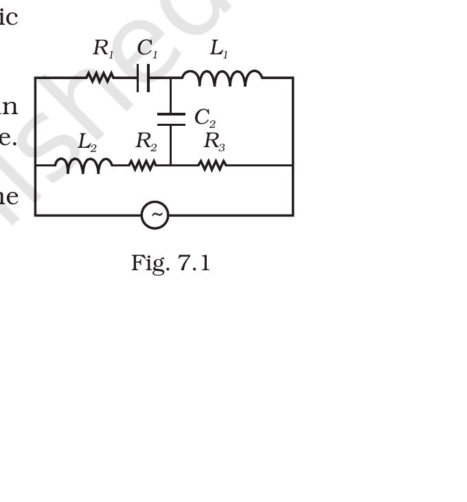
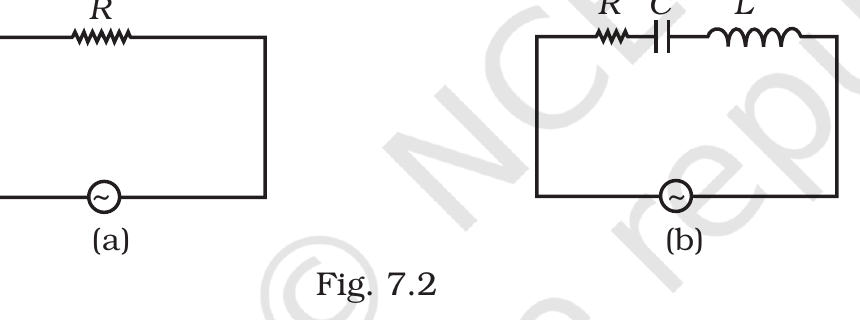
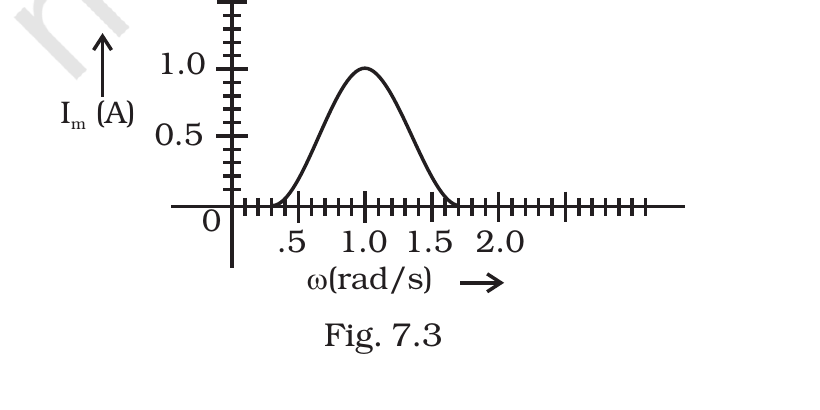
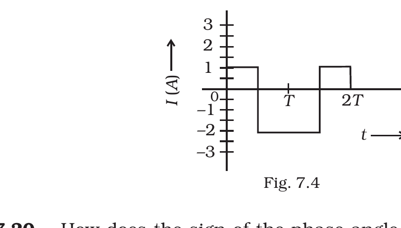
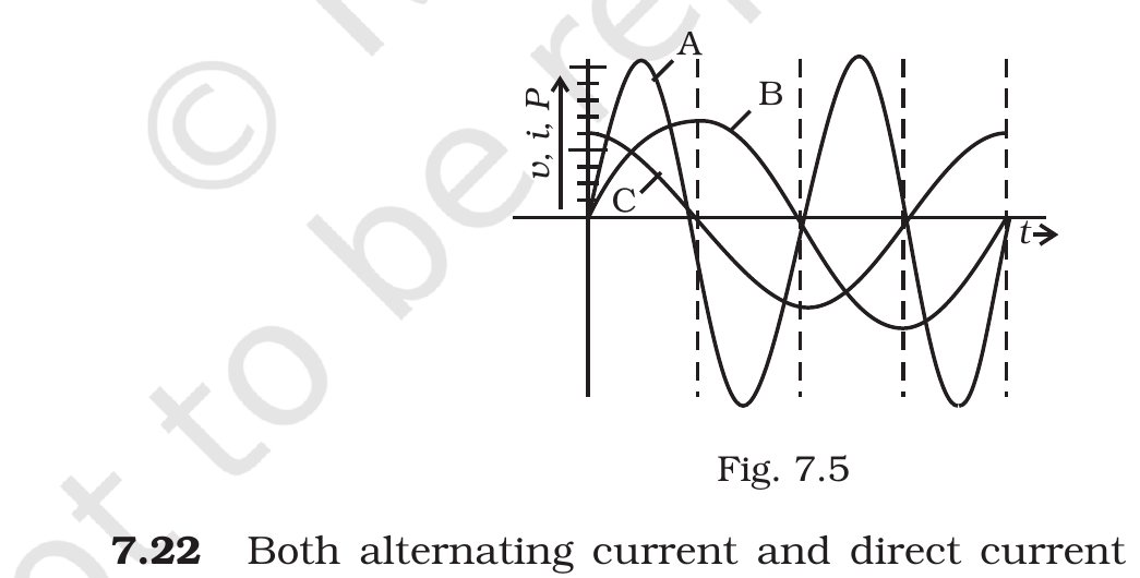
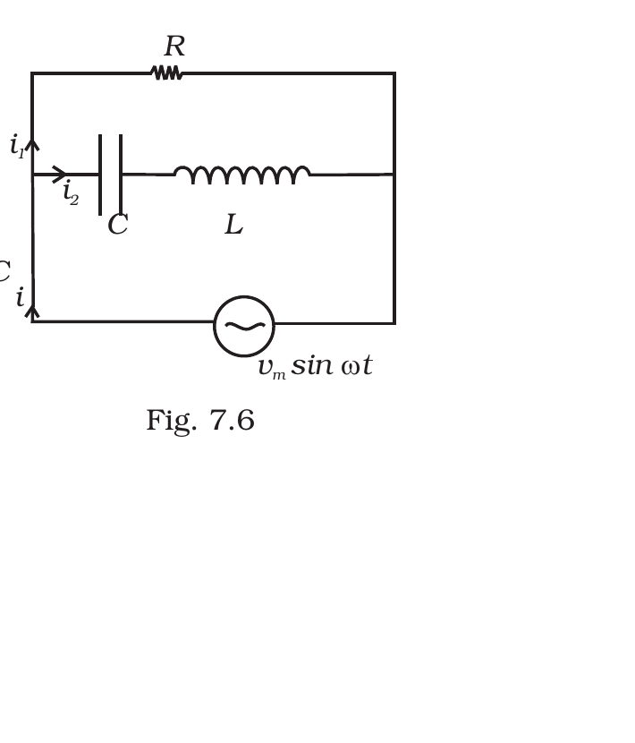
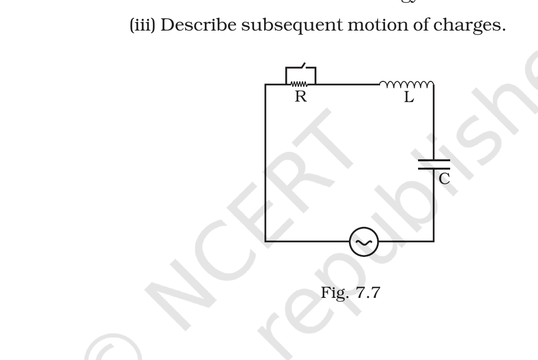



Comments