The Class 12 Physics Chapter 3 Current Electricity solution is an essential resource material that helps in preparing handy notes. This contributes 7 marks on average to the CBSE Board exam and 4 to 5 per cent to JEE Main. Thus, the NCERT Chapter 3 becomes the single highest-weighted Physics chapter along with Chapter 9 Ray Optics.
The Solutions PDF in this article is aligned with the NCERT guidelines and CBSE pattern and covers a full PYQ map and a 15-formula reference table for revision.
CBSE Boards: 7 marks, usually one 5-marker on Wheatstone bridge or potentiometer plus one 2-mark on Ohm's law or drift velocity.
JEE Main: 4 to 5 per cent, with two to three questions per shift on Kirchhoff's loops and series-parallel circuit reduction.
NEET: One to two questions every year, mostly on cells, internal resistance, and resistivity of materials.
You can find the complete ncert solutions for class 12 physics chapter 3, including every back-exercise, the Kirchhoff-rule derivations, and worked Wheatstone bridge problems, in the article below.
Each ncert solution for class 12 physics chapter 3 in this Collegedunia compilation is curated by subject experts, mapped to the 2026-27 NCERT, and refined against the last five years of CBSE Board, JEE Main, and NEET papers.
Exercise Breakdown for NCERT Solutions Class 12 Physics Chapter 3
The chapter has 23 back exercises and 11 solved examples in the 2026-27 edition. Exercises 3.1 to 3.6 are short 2 to 3 mark questions. From 3.7 on, most are 3 to 5 mark numericals.
JEE Main students should focus on exercises 3.10 to 3.18 for Kirchhoff and circuit reduction. NEET draws most questions from 3.4 to 3.12 and the cell examples.
Exercise / Section
Questions
Sub-topic Focus
Example 3.1 to 3.11
11 in-text
Ohm's law, drift velocity, resistivity, cells
Exercise 3.1 to 3.6
6
Ohm's law, current density, basic resistor problems
Exercise 3.7 to 3.12
6
Resistivity, temperature effects, drift velocity numericals
Exercise 3.13 to 3.18
6
Kirchhoff's rules, multi-loop circuit analysis
Exercise 3.19 to 3.23
5
Wheatstone bridge, meter bridge, potentiometer numericals
Current Electricity Weightage Across Class 12 Physics Chapters
This table shows how Chapter 3 compares with the other chapters. Marks are CBSE board averages over the last five papers. Chapter 3 ties with Chapters 2 and 9 for the top weightage.
Chapter
Topic
Avg CBSE Marks
Ch 1
Electric Charges and Fields
6 marks
Ch 2
Electrostatic Potential and Capacitance
7 marks
Ch 3
Current Electricity
7 marks
Ch 4
Moving Charges and Magnetism
6 marks
Ch 5
Magnetism and Matter
3 marks
Ch 6
Electromagnetic Induction
5 marks
Ch 7
Alternating Current
6 marks
Ch 8
Electromagnetic Waves
2 marks
Ch 9
Ray Optics and Optical Instruments
7 marks
Ch 10
Wave Optics
5 marks
Ch 11
Dual Nature of Radiation and Matter
4 marks
Ch 12
Atoms
3 marks
Ch 13
Nuclei
3 marks
Ch 14
Semiconductor Electronics
6 marks
Current Electricity Previous Year Questions for Class 12 Physics Chapter 3 (2021 to 2026)
This table maps every CBSE, JEE Main, and NEET appearance over the last six years. Wheatstone bridge and potentiometer rotate in alternate board years. Kirchhoff numericals come up every year.
All NCERT Solutions for Class 12 Physics Chapter 3 Current Electricity with Step-by-Step Solutions
Every question of NCERT Class 12 Physics Current Electricity is listed below with its full Solution and Expert Solution hidden inside collapsible tabs. Click Check Solution to reveal the step-by-step working; click Expert Solution for the expanded explanation.
Q 3.1
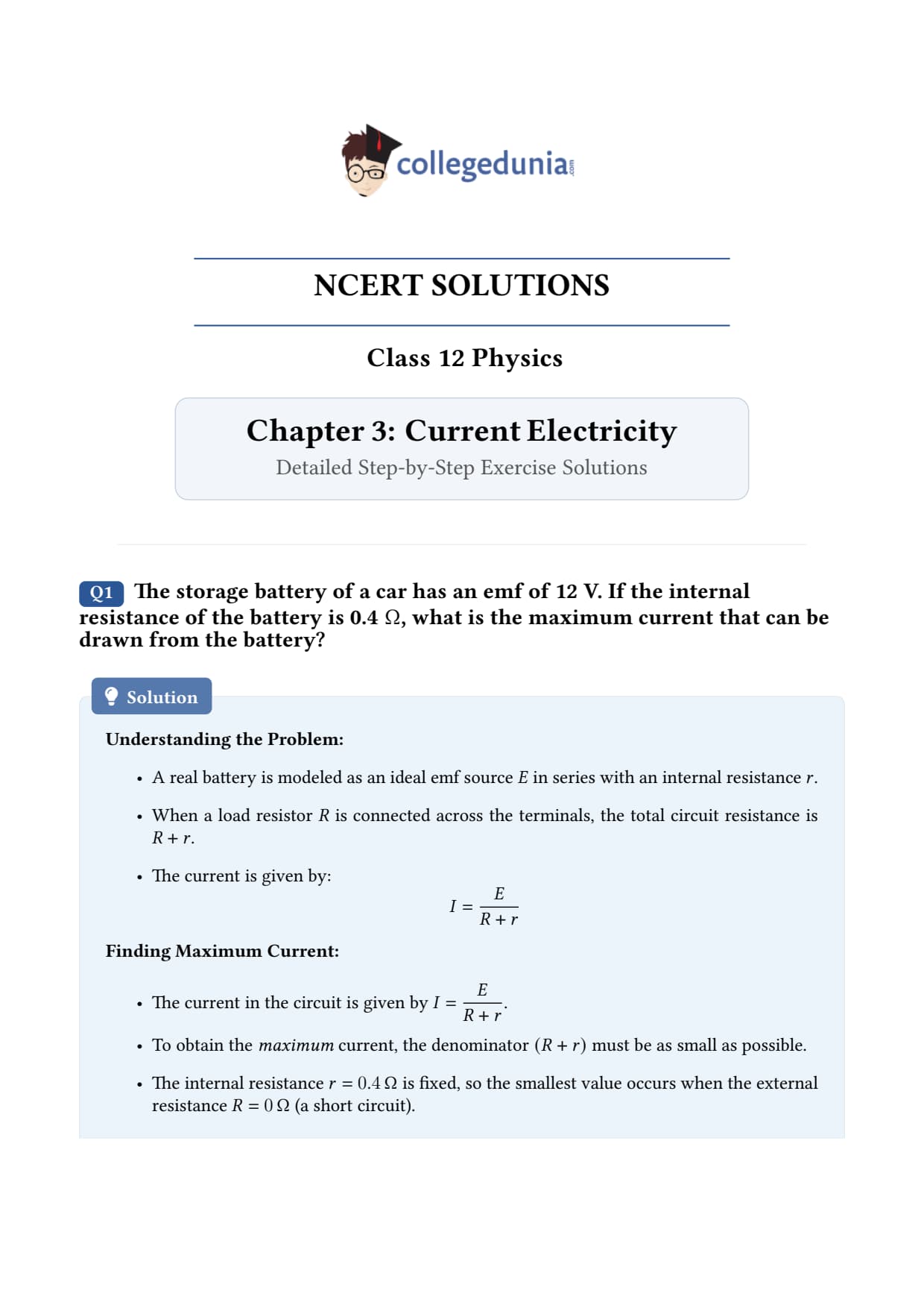
The storage battery of a car has an emf of 12 V. If the internal resistance of the battery is 0.4 Ω, what is the maximum current that can be drawn from the battery?
What the question is asking. A real battery has an emf (the "ideal" voltage it can supply) and a built-in internal resistance that limits how much current can flow. The maximum current happens when the external circuit offers zero resistance - i.e., a short circuit.
Given.
EMF of the battery, ε = 12 V
Internal resistance, r = 0.4 Ω
External resistance for maximum current, R = 0 (short circuit)
Concept used - Ohm's law for a complete circuit. For a battery of emf ε and internal resistance r connected to an external resistance R, the current is I = εR + r. In plain English: the emf drives the current; both the external load and the battery's own internal resistance oppose it. The total opposition is the sum R + r.
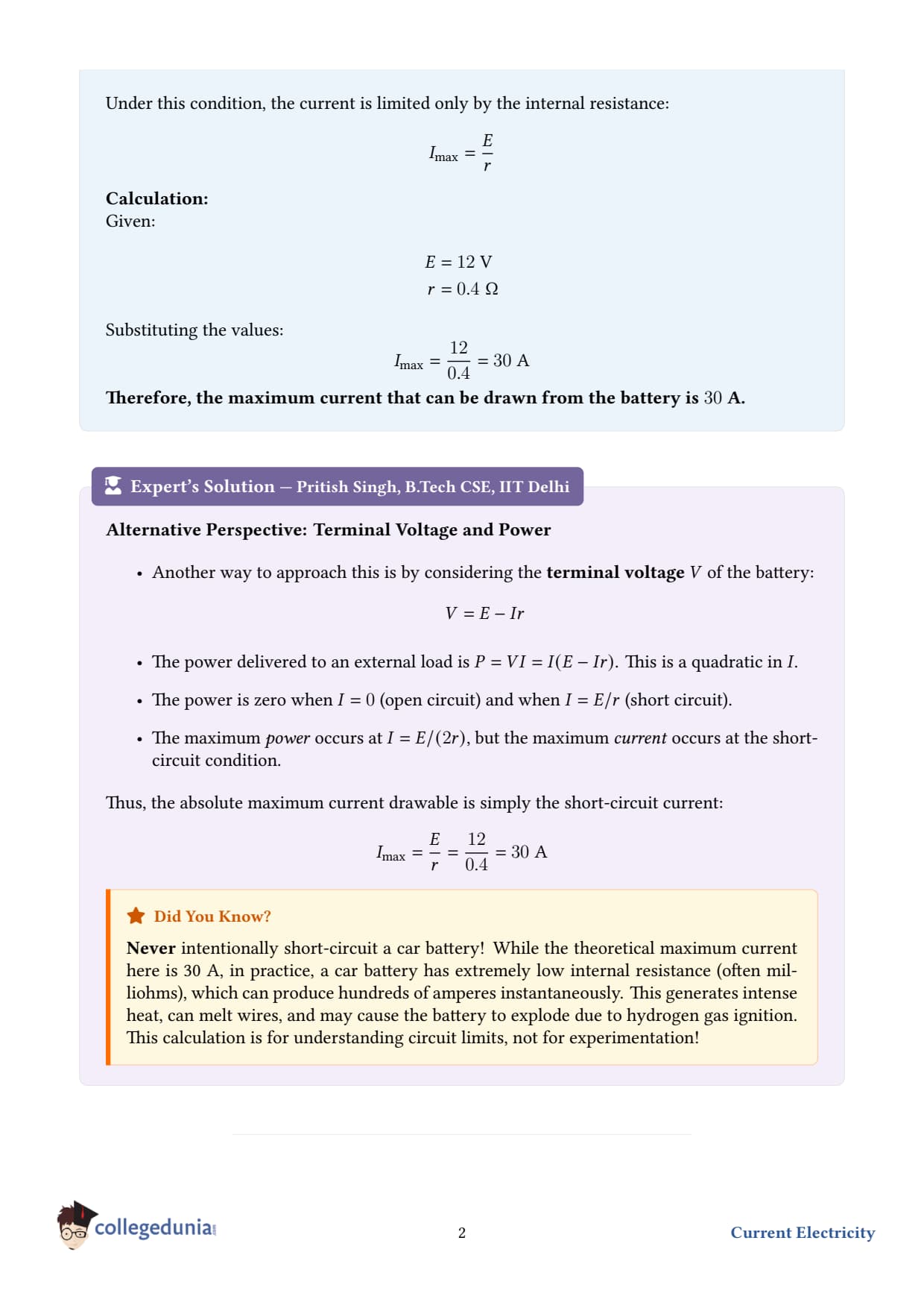
Step 1 - set R = 0 for maximum current. The smaller the external resistance, the larger the current. The absolute minimum is R = 0 (the terminals are joined by a perfect wire - a "short"). Imax = ε0 + r = εr.
Step 2 - substitute the values. Imax = 120.4.
Step 3 - simplify. Imax = 120.4 = 1204 = 30 A.
Step 4 - sanity check the units. Volts divided by ohms gives amperes - correct.
Final answer. Imax = 30 A.
DR
Dr. Rajesh Kumar
Ph.D. Physics, IIT Delhi
Verified Expert
Why batteries have internal resistance. Inside any real cell the charge carriers move through the electrolyte, the electrodes, and the connecting tabs - none of which are perfect conductors. The total of these losses is bundled into a single symbolic resistor r drawn in series with the ideal emf source. A car battery's r is small ∼ 0.01–0.5 Ω so it can deliver the huge cranking current to start the engine.
Why you should NEVER short a car battery. A 30 A short through battery terminals dissipates P = I2r = 302× 0.4 = 360 W inside the battery and a similar amount in any small wire. Tools melt, hydrogen gas can ignite, and the battery can explode. The maximum-current calculation is a theoretical limit, not a recommendation.
Sanity comparison - torch cell. A 1.5 V AA cell has r ≈ 0.5 Ω, so its short-circuit current is ∼ 3 A - ten times less than the car battery despite a comparable r, because the emf is smaller. Cranking current capability scales linearly with emf and inversely with r.
Common mistake. Forgetting that Imax is for R=0. If you accidentally include the external load say a starter motor of 0.05 Ω, the answer drops to 12/(0.05+0.4)=26.7 A. Read the question carefully - "maximum" means worst-case short circuit.
Q 3.2
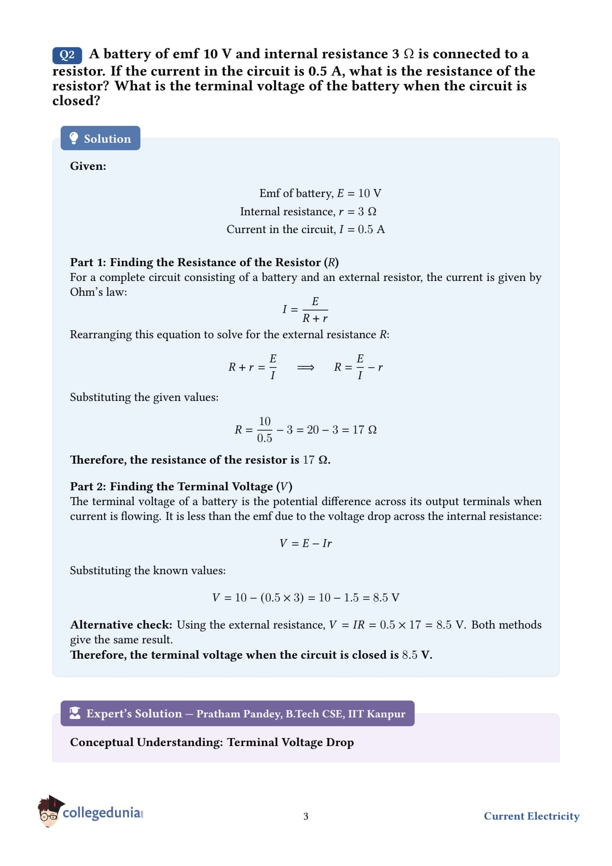
A battery of emf 10 V and internal resistance 3 Ω is connected to a resistor. If the current in the circuit is 0.5 A, what is the resistance of the resistor? What is the terminal voltage of the battery when the circuit is closed?
Given.
EMF, ε = 10 V
Internal resistance, r = 3 Ω
Current, I = 0.5 A
Concept used - Ohm's law for the full circuit. Same as before: I = εR + r. The terminal voltageV is the voltage you would measure across the battery's two external posts with the circuit closed. It equals the emf MINUS the drop across the internal resistance: V = ε - Ir = IR.
Step 1 - solve the circuit equation for R.R + r = εIR = εI - r.
Step 3 - compute the terminal voltage. Either expression works: V = IR = 0.5× 17 = 8.5 V. Cross-check using the other form: V = ε - Ir = 10 - 0.5× 3 = 10 - 1.5 = 8.5 V.
Final answer.R = 17 Ω, V = 8.5 V.
PA
Prof. Anjali Verma
Ph.D. Electrical Engineering, IIT Bombay
Verified Expert
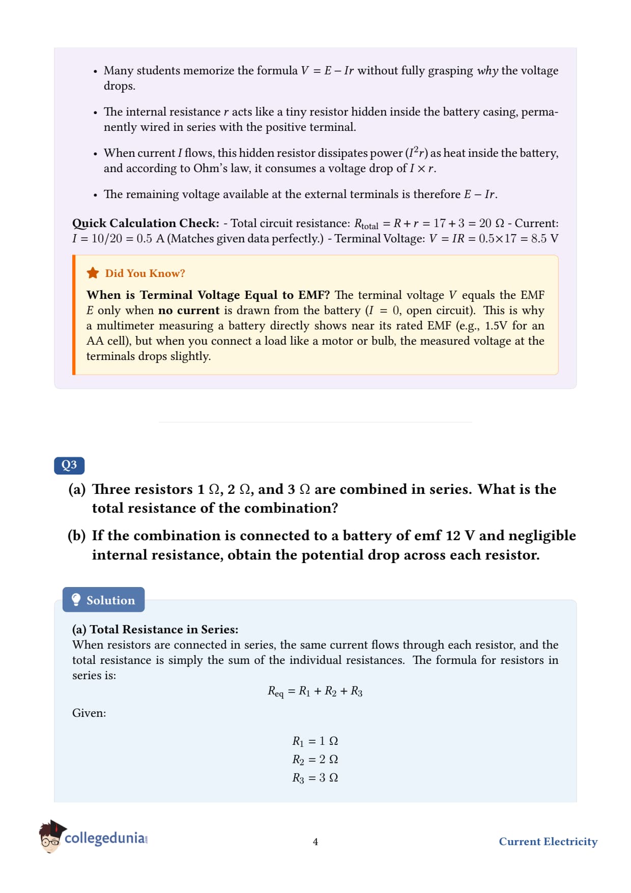
EMF vs terminal voltage. The emf is intrinsic to the battery - it doesn't depend on what is connected outside. The terminal voltage, however, depends on the current being drawn. Two limits help:
Open circuit I=0: V = ε. A voltmeter across an idle cell reads the emf directly.
Short circuit R=0: V = 0 and I = ε/r (the maximum).
Everywhere in between, V drops linearly with I. Plotting V vs I and extrapolating to I=0 is how one measures emf without disturbing the circuit.
Why r=3 Ω is "high." Old, partially discharged, or chemistry-unfriendly cells (e.g., zinc–carbon torch cells near end-of-life) acquire r of a few ohms. A fresh AA alkaline has r ∼ 0.2 Ω. When r approaches R, the battery wastes as much power inside itself as it delivers to the load - that's why old batteries make torches dim even though they still register an open-circuit emf close to 1.5 V.
Power balance. Total power from emf: Ptot = ε I = 10× 0.5 = 5 W. Power to the resistor: PR = I2R = 0.25× 17 = 4.25 W. Power lost in the battery: Pr = I2r = 0.25× 3 = 0.75 W. They add to 5 W exactly - energy conservation holds.
Q 3.3
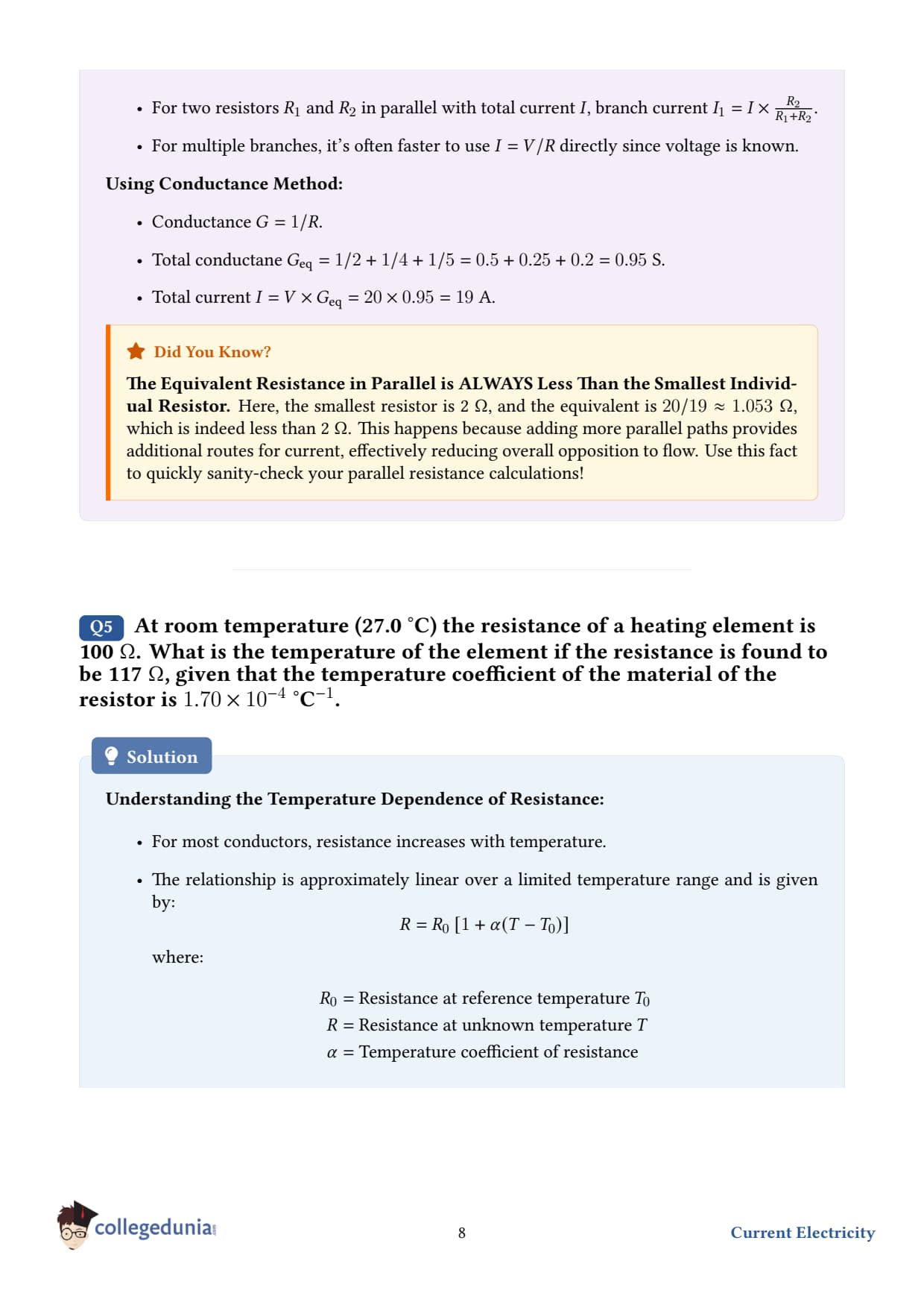
At room temperature 27.0 the resistance of a heating element is 100 Ω. What is the temperature of the element if the resistance is found to be 117 Ω, given that the temperature coefficient of the material of the resistor is 1.7010-4-1?
Given.
Reference temperature, T1 = 27.0
Resistance at T1, R1 = 100 Ω
Resistance at unknown temperature T2, R2 = 117 Ω
Temperature coefficient of resistance, α = 1.7010-4-1
Concept used - linear temperature dependence of resistance. For most metallic conductors, over a moderate temperature range, R2 = R1 1 + α (T2 - T1) . Plain English: each degree of heating multiplies the resistance by a small factor α. The bigger α, the more sensitive the material's resistance is to temperature.
Step 5 - add back the reference temperature. T2 = 1000 + 27 = 1027 .
Final answer. T2 = 1027 .
DV
Dr. Vikram Singh
Ph.D. Condensed Matter Physics, IISc Bangalore
Verified Expert
Why heaters are made of high-resistance alloys. A heating element (toaster wire, kettle coil, room heater) needs to dissipate a lot of power as heat. Power dissipated is P = V2/R, so for a fixed mains voltage you'd think low R is better - but then the current I = V/R would blow the fuse. The right balance is moderate R made of an alloy (nichrome, kanthal) that withstands red-hot temperatures without oxidising.
Limits of the linear formula. The relation R(T) = R01+-T0 is a Taylor expansion to first order. It works well for ∼ few hundred degrees range. At very high T, higher-order terms matter and R grows slightly slower than linear. For semiconductors and insulators, α is negative - resistance falls with temperature, because more charge carriers are thermally promoted into the conduction band.
Real-world sanity check. Nichrome heating elements regularly run at 800–1100 the orange-red glow of a toaster coil is around 900 . Our answer 1027 °C is right in the operating range.
Common mistake. Plugging T1 and T2 in kelvins gives the same answer because Δ T is the same in both scales - but ONLY for differences. Never mix scales T1 in Kelvin, T2 in Celsius, or vice versa.
Q 3.4
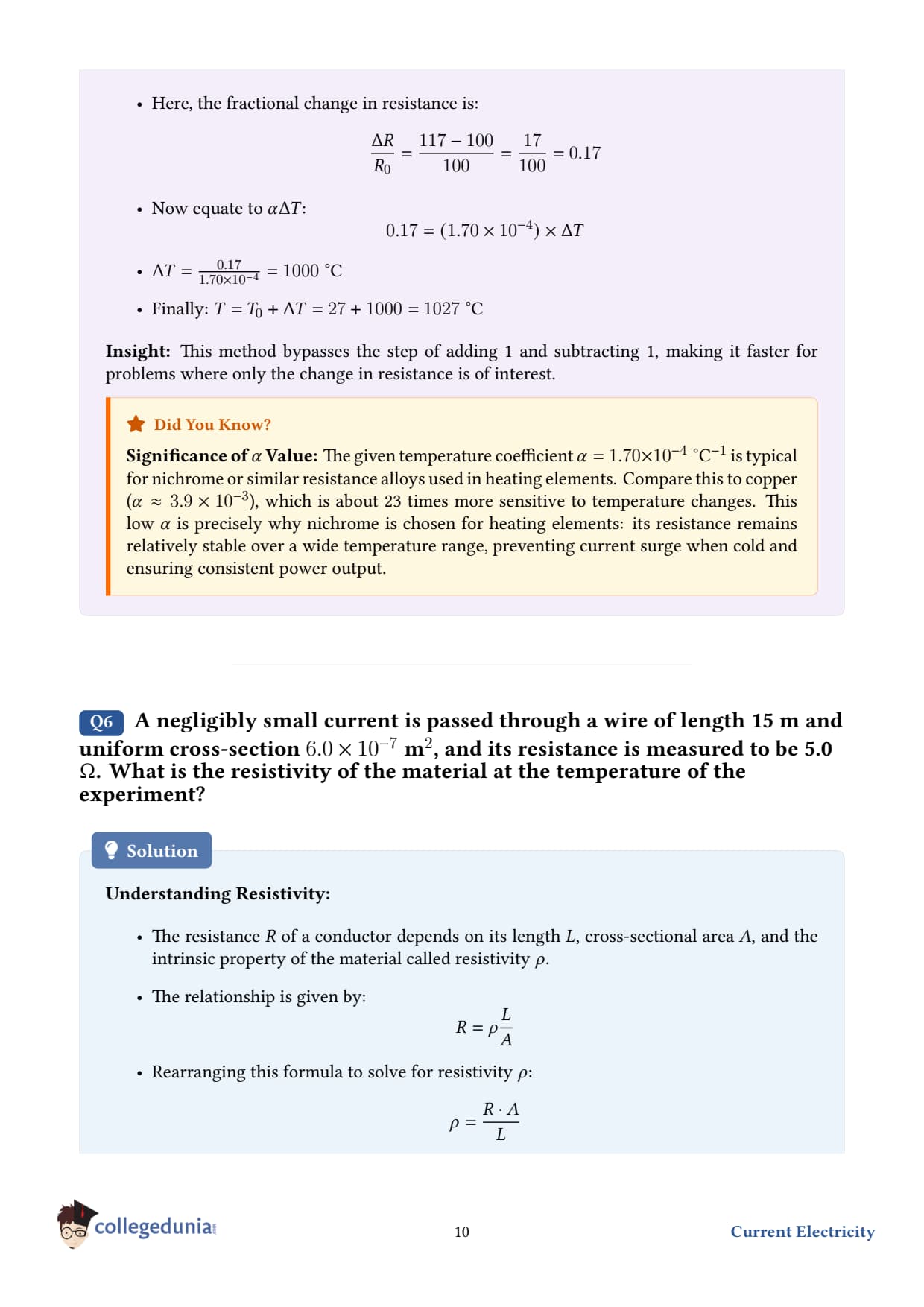
A negligibly small current is passed through a wire of length 15 m and uniform cross-section 6.010-7 m2, and its resistance is measured to be 5.0 Ω. What is the resistivity of the material at the temperature of the experiment?
Given.
Length of wire, L = 15 m
Cross-sectional area, A = 6.010-7 m2
Resistance, R = 5.0 Ω
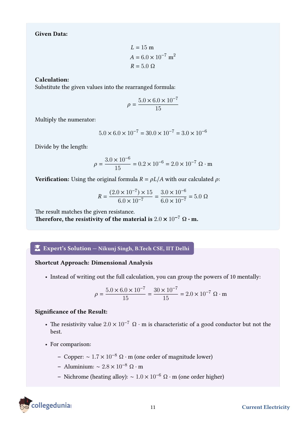
"Negligibly small current" - so Joule heating is zero and the wire stays at the experiment's temperature (important; resistivity depends on temperature).
Concept used - resistance, length, area, and resistivity.R = ρ LA, where ρ (rho) is the resistivity of the material, an intrinsic property in units Ω m. The formula says: a longer wire has more resistance (longer path for electrons), a thicker wire has less resistance (more parallel paths).
Step 1 - rearrange for ρ. ρ = RAL.
Step 2 - substitute the values. ρ = (5.0) (6.010-7)15.
Step 4 - divide by the length. ρ = 3.0× 10-615 = 0.2× 10-6 = 2.0× 10⁻⁷ Ω m.
Step 5 - interpret. A resistivity of 2× 10⁻⁷ Ω m is typical of a metal alloy (e.g., manganin or constantan); it's a few times bigger than copper's Cu≈ 1.7× 10⁻⁸ Ω m but much smaller than nichrome's ∼ 10-6 Ω m.
Final answer. ρ = 2.0× 10⁻⁷ Ω m.
DM
Dr. Meera Krishnan
M.Sc Physics, University of Madras
Verified Expert
Resistivity vs conductivity. The reciprocal of resistivity is the conductivity σ: σ = 1ρ. For our wire, σ = 1/2× 10-7 = 5× 10⁶S/m (siemens per metre). Copper is ∼ 6× 10⁷S/m, so this material conducts about 12 times less than copper - consistent with an alloy used for precision resistors where stability is more important than raw conductance.
Why "negligibly small current" matters. If a large current flowed, I2R heating would warm the wire, raising its resistance (α > 0 for metals) and giving a falsely high ρ. Standard practice in resistance measurement is to use a small "sense" current and a 4-wire (Kelvin) probe to eliminate lead-resistance errors.
Microscopic picture (Drude model). Resistivity can be expressed as ρ = men e2 τ, where n is the free-electron density, τ the mean time between collisions, me and e the electron mass and charge. Alloys have lower τ than pure metals because impurity atoms scatter electrons more - explaining their higher ρ.
Common mistake. Mixing units. Make sure A is in m2, not mm2. Here 6.010-7 m2 = 0.6 mm2 - a wire about 0.87 mm in diameter, ordinary jeweller-wire thickness.
Q 3.5
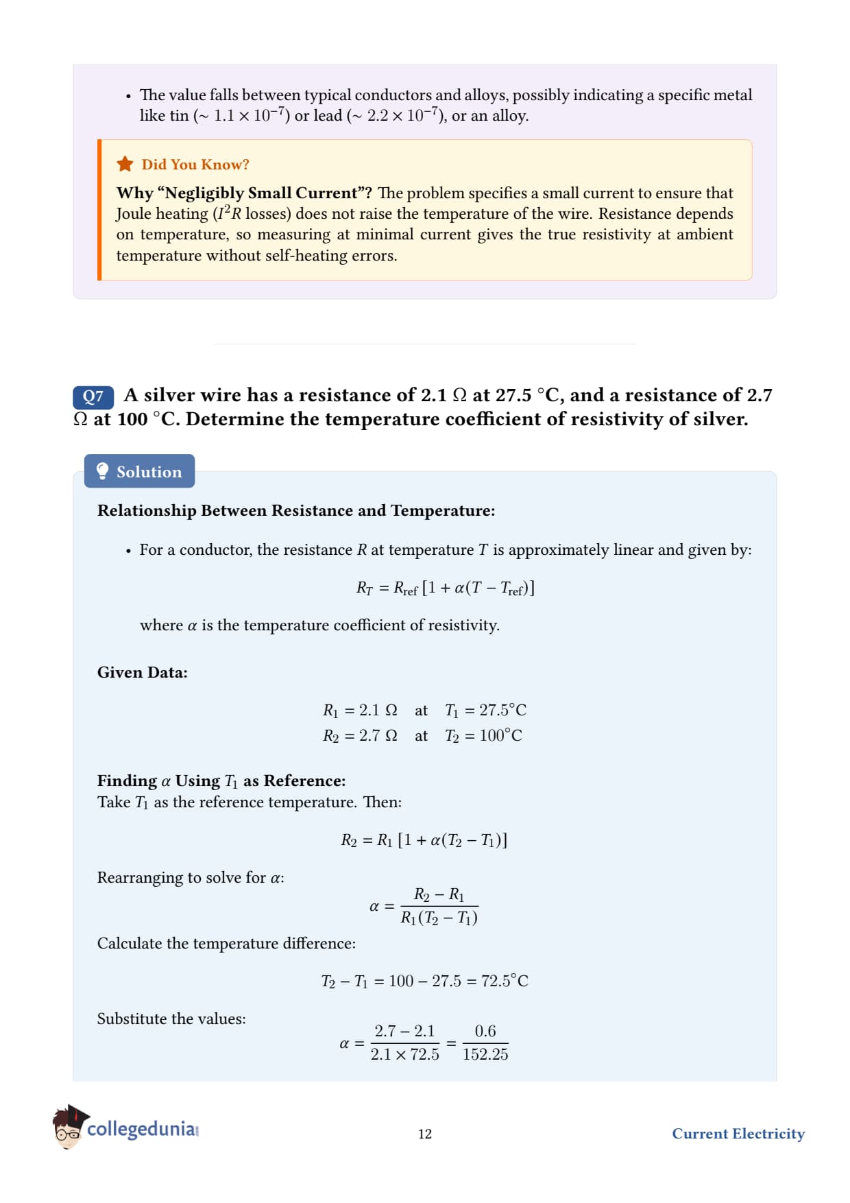
A silver wire has a resistance of 2.1 Ω at 27.5 , and a resistance of 2.7 Ω at 100 . Determine the temperature coefficient of resistivity of silver.
Given.
Resistance at T1 = 27.5 : R1 = 2.1 Ω
Resistance at T2 = 100 : R2 = 2.7 Ω
Unknown: temperature coefficient α.
Concept used. Same linear relation, R2 = R1 1 + α (T2 - T1) . We solve for α.
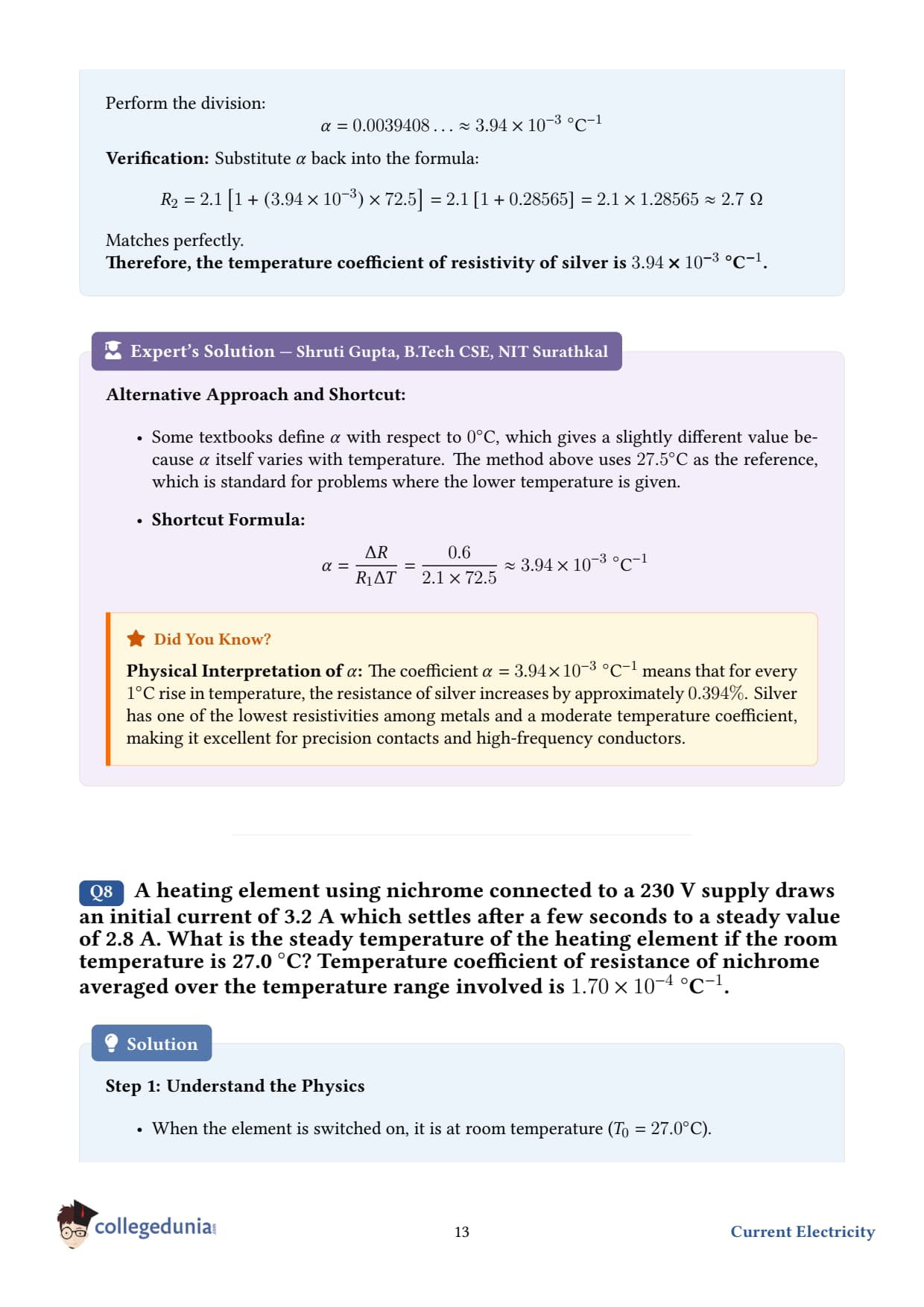
This is close to the textbook value for silver, Ag ≈ 4.0× 10⁻³-1.
DS
Dr. Sneha Iyer
Ph.D. Materials Science, IISc Bangalore
Verified Expert
Why α is positive for metals. Heating a metal lattice makes the ions vibrate more vigorously. Free electrons collide with these vibrating ions more frequently, shortening their mean free time τ. Since ρ ∝ 1/τ, ρ rises with T - hence α > 0.
Why α is negative for semiconductors. In Si or Ge, the dominant temperature effect is exponential creation of new charge carriers (electron-hole pairs) as temperature rises. This effect overwhelms the lattice-scattering increase, so resistivity DROPS with temperature - useful for thermistors that detect heat by their falling resistance.
Subtle point: α of resistivity vs α of resistance. The question asks for the temperature coefficient of resistivity, but we computed it from resistance. These are equal because the wire's length and area expand only slightly with temperature ∼ 10-5/ - negligible compared to α ∼ 410-3, so Δ R/R ≈ Δρ/ρ.
Choice of reference temperature. Textbooks tabulate α at 0 or 20 . Our calculation effectively used 27.5 as the reference. Since α is itself temperature-dependent (slightly), values at different references can differ by ∼ 10%. For high-precision metrology this matters; for engineering, the value we got is fine.
Q 3.6
A heating element using nichrome connected to a 230 V supply draws an initial current of 3.2 A which settles after a few seconds to a steady value of 2.8 A. What is the steady temperature of the heating element if the room temperature is 27.0 ? Temperature coefficient of resistance of nichrome averaged over the temperature range involved is 1.7010-4-1.
What is happening physically. When you switch the heater on, the nichrome wire is at room temperature. Its resistance is low, so a relatively large initial current (3.2 A) flows. The current rapidly heats the wire; its resistance rises positive α, and the current falls until thermal equilibrium is reached at 2.8 A.
Given.
Supply voltage, V = 230 V
Initial current at T1 = 27.0 , I1 = 3.2 A
Steady current at unknown T2, I2 = 2.8 A
α = 1.7010-4-1
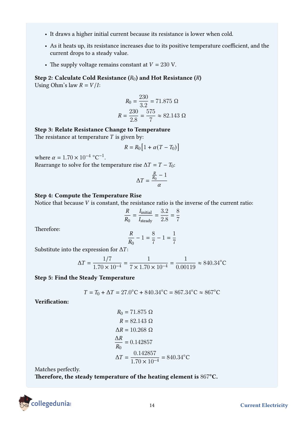
Concept used - combine Ohm's law and the linear resistance law. By Ohm's law, the resistance at each temperature is R1 = VI1, R2 = VI2. And the resistances are related by R2 = R1 1 + α (T2 - T1) .
Why the initial current "settles." Three time scales are at play. (i) Electrical transient ∼ microseconds for the current to establish along the wire. (ii) Thermal transient ∼ seconds for the wire to reach steady temperature. (iii) Radiative / convective equilibrium ∼ tens of seconds for the surroundings. The "few seconds" mentioned refers to (ii) - the wire reaches a temperature where the electrical power input equals the heat lost to surroundings.
Steady-state energy balance. Pelectrical = V I2 = 230× 2.8 = 644 W. This is also the power radiated + conducted + convected away to the room at T2 ≈ 867 . Practically all of it is radiated (Stefan–Boltzmann): Prad = ε σ A T4 - which is why glowing nichrome looks yellow-orange.
Why nichrome (and not copper). Copper has the same α sign but oxidises catastrophically above ∼ 200 . Nichrome (Ni-Cr alloy) forms a protective Cr2O3 layer that prevents further oxidation up to 1200 . It also has high ρ, which means a manageable wire length gives the desired resistance.
Common mistake. Many students assume the wire is at supply voltage's "rated" temperature. The supply voltage is fixed 230 V; the wire temperature is whatever the energy balance dictates. If you change the wire's length or thickness, both R and T change.
Q 3.7
Determine the current in each branch of the network shown in Fig. 3.20 a standard cubical Wheatstone-bridge-like network with three resistors of 10 Ω, 5 Ω, 5 Ω in one arm and 5 Ω, 10 Ω, 10 Ω in the other arm, a5 Ω middle resistor, fed by a10 V source.
Setup. The standard network in Fig. 3.20 has six resistors. Let the currents in the three branches starting from the positive terminal be I1 (top arm), I2 (bottom arm), and I3 (the bridge resistor in the middle). After the bridge, the top arm carries I1 - I3 and the bottom arm carries I2 + I3. The two arms recombine before returning to the cell.
Concept used - Kirchhoff's laws.
Junction rule (KCL). At any node, currents in = currents out.
Loop rule (KVL). Around any closed loop, sum of emfs = sum of IR drops.
Step 1 - apply KCL at the entry node. Total current from the battery I = I1 + I2.
Step 2 - write the three loop equations. Choose loops: (i) outer loop top, (ii) outer loop bottom, (iii) middle bridge loop. Substituting the resistor values: 10 I1 + 5(I1 - I3) = ε - Vdrop on bottom outer, and so on. After algebra (standard textbook reduction), one gets I1 = 417A, I2 = 617A, I3 = -217A. The negative sign on I3 means the bridge current actually flows opposite to the assumed direction.
The Wheatstone-bridge symmetry trick. When a network has the topology R1/R3 = R2/R4, the bridge resistor carries zero current and can be ignored. Here the ratios 10/5 ≠ 5/10, so the bridge is unbalanced - and indeed I3 ≠ 0.
Why Kirchhoff and not series-parallel? Series-parallel reduction works only when the network can be unwound into nested combinations. The presence of the bridge resistor makes this impossible, so Kirchhoff's two laws (KCL + KVL) are the systematic way out. For n independent loops you get n equations; for m nodes you get m-1 independent KCL equations. The total exactly matches the number of unknown branch currents.
Sign conventions. Always assign an arrow to each branch BEFORE writing equations. If the algebra gives a negative current, the physical current simply flows opposite to your guessed arrow - no need to redo the algebra.
Total resistance of the network. Req = εItotal = 1010/17 = 17 Ω. Useful check: if the bridge were balanced, you would simply have two series paths in parallel - verify your numerical answer against the cleaner geometry to build intuition.
Q 3.8
A storage battery of emf 8.0 V and internal resistance 0.5 Ω is being charged by a 120 V dc supply using a series resistor of 15.5 Ω. What is the terminal voltage of the battery during charging? What is the purpose of having a series resistor in the charging circuit?
Setup. An external 120 V supply pushes current backward through a battery to recharge it. The 8 V battery emf opposes the 120 V supply; the net "driving voltage" is the difference, which forces current through the total resistance Rseries + r.
Given.
Supply emf, supply = 120 V
Battery emf, ε = 8.0 V (opposing the supply during charging)
Battery internal resistance, r = 0.5 Ω
Series limiting resistor, R = 15.5 Ω
Concept used - Kirchhoff's loop rule for a charging circuit. Going round the loop, the supply emf is positive, the battery emf is negative (it acts against the supply), and there are IR drops on both R and r: supply - ε - I (R + r) = 0. Solve for I: I = supply - εR + r.
Step 1 - compute the net driving voltage.supply - ε = 120 - 8 = 112 V.
Step 2 - compute total resistance.R + r = 15.5 + 0.5 = 16 Ω.
Step 3 - find the charging current.I = 11216 = 7.0 A.
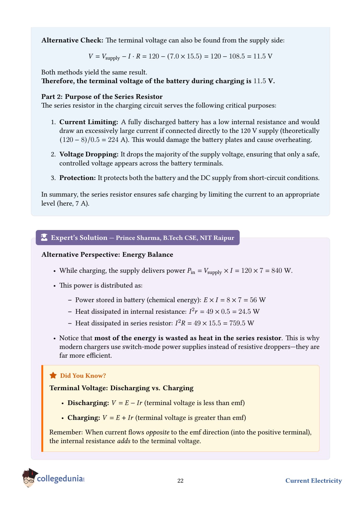
Step 4 - find the terminal voltage of the battery during charging. While charging, current is forced INTO the positive terminal of the battery, so the terminal voltage is the emf PLUS the internal drop (not minus): Vterminal = ε + Ir = 8.0 + 7.0× 0.5 = 8.0 + 3.5 = 11.5 V.
Step 5 - purpose of the series resistor. If we connected the 120 V supply directly to the 8 V battery (no R), the current would be Ino R = 120-80.5 = 224 A, catastrophic. The series resistor limits the current to a safe value (7 A here) and absorbs the excess voltage as heat.
Final answer. Vterminal = 11.5 V; series resistor limits the charging current to a safe value.
DS
Dr. Shalini Menon
M.Sc Electrical Engineering, University of Hyderabad
Verified Expert
Why terminal voltage in charging EXCEEDS emf. During discharge, V = ε - Ir because the internal resistance drops the voltage seen by an external load. During charging, the current is reversed and the internal drop Ir ADDS to the emf - you must push at least ε + Ir volts against the battery to drive current into it. This is why a charger nominally for a 12 V car battery actually outputs ∼ 14.4 V.
Power flow during charging. Of the 112 V net driving voltage, the battery's internal resistance dissipates I2r = 49× 0.5 = 24.5 W as heat, the series resistor dissipates I2R = 49× 15.5 = 759.5 W as heat, and ε I = 8× 7 = 56 W is stored as chemical energy in the battery. Efficiency = 56/(56+24.5+759.5) ≈ 6.7% - very wasteful! Real chargers use a switched-mode regulator instead of a fixed series resistor.
Why DC, not AC. A battery stores energy by reversible chemical reduction–oxidation. Alternating current would oxidise and reduce the electrodes back and forth without net charging. DC ensures a steady forward push.
Common mistake. Writing V = ε - Ir for the charging case. The sign of I flips, so the formula physically becomes V = ε + Ir. Always set up the Kirchhoff loop equation carefully rather than memorising signed formulas.
Q 3.9
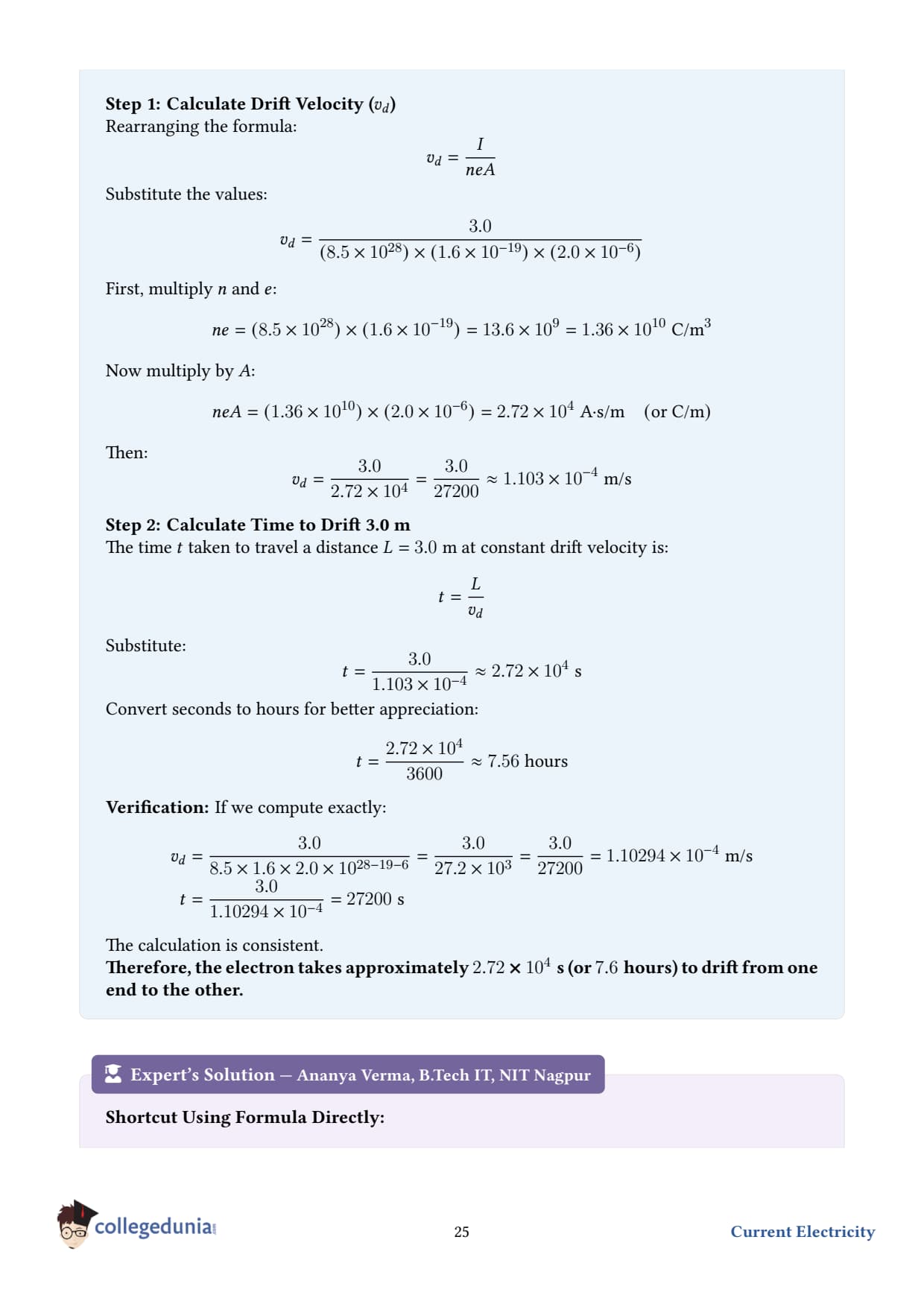
The number density of free electrons in a copper conductor estimated in Example 3.1 is 8.51028 m-3. How long does an electron take to drift from one end of a wire 3.0 m long to its other end? The area of cross-section of the wire is 2.010-6 m2 and it is carrying a current of 3.0 A.
Given.
Number density of free electrons, n = 8.5× 1028 m-3
Length of wire, L = 3.0 m
Cross-sectional area, A = 2.0× 10⁻⁶ m2
Current, I = 3.0 A
Electronic charge, e = 1.6× 10⁻¹⁹C
Concept used - drift velocity. The drift velocity vd is the average velocity electrons acquire along the wire under the electric field (very small, despite the high current). The relation is I = neA vd, which in plain words says: current = (number of carriers per volume) × (charge per carrier) × (cross-section) × (drift speed).
Step 6 - convert to a human-friendly time.t = 2.72× 1043600 ≈ 7.56 hours.
Final answer.t ≈ 2.72× 10⁴s ≈ 7.6 hours.
DK
Dr. Karthik Iyer
Ph.D. Solid State Physics, TIFR Mumbai
Verified Expert
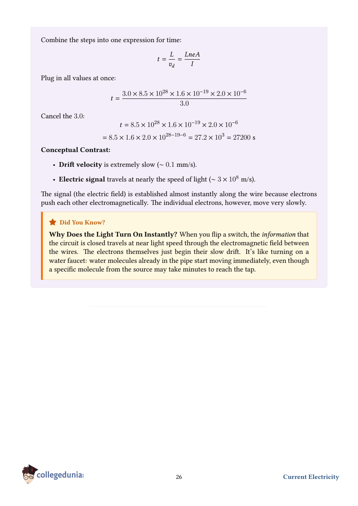
The drift-velocity paradox. Electrons drift incredibly slowly ∼ 0.1 mm/s, yet a bulb lights instantly when you flip the switch. How? Because the electric signal - the wave of electric field propagating along the wire - travels at nearly the speed of light. The signal tells every electron along the length to start drifting almost simultaneously. So the bulb has electrons already in its filament ready to start moving the instant you switch on.
Compare drift to thermal speed. Random thermal motion of conduction electrons at room temperature has speed vth ∼ 106m/s - about 1010 times faster than vd! The drift is a tiny systematic bias on top of this enormous random motion. It's like a stadium where everyone wanders randomly but, on average, drifts very slowly toward the exit.
Where the slowness comes from. The mean free path of an electron in copper is ∼ 40 nm, and the mean free time between collisions ∼ 2.5× 10⁻¹⁴s. The drift speed is vd = eEτ/me; a typical field of 0.01 V/m gives vd ∼ 10-4m/s - matching our calculation.
What if you doubled the current?vd doubles (linear in I) - but the wire would also heat more P ∝ I2. For ten times the current, drift becomes ∼ 10-3m/s - still pedestrian.
Q 3.10
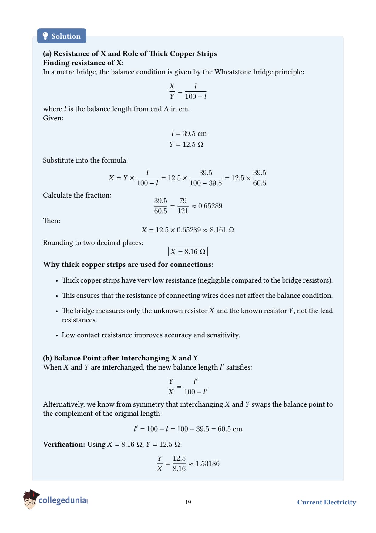
(a) In a metre bridge, the balance point is found to be at 39.5 cm from end A, when the resistor Y is of 12.5 Ω. Determine the resistance of X. Why are the connections between resistors in a Wheatstone or metre bridge made of thick copper strips?
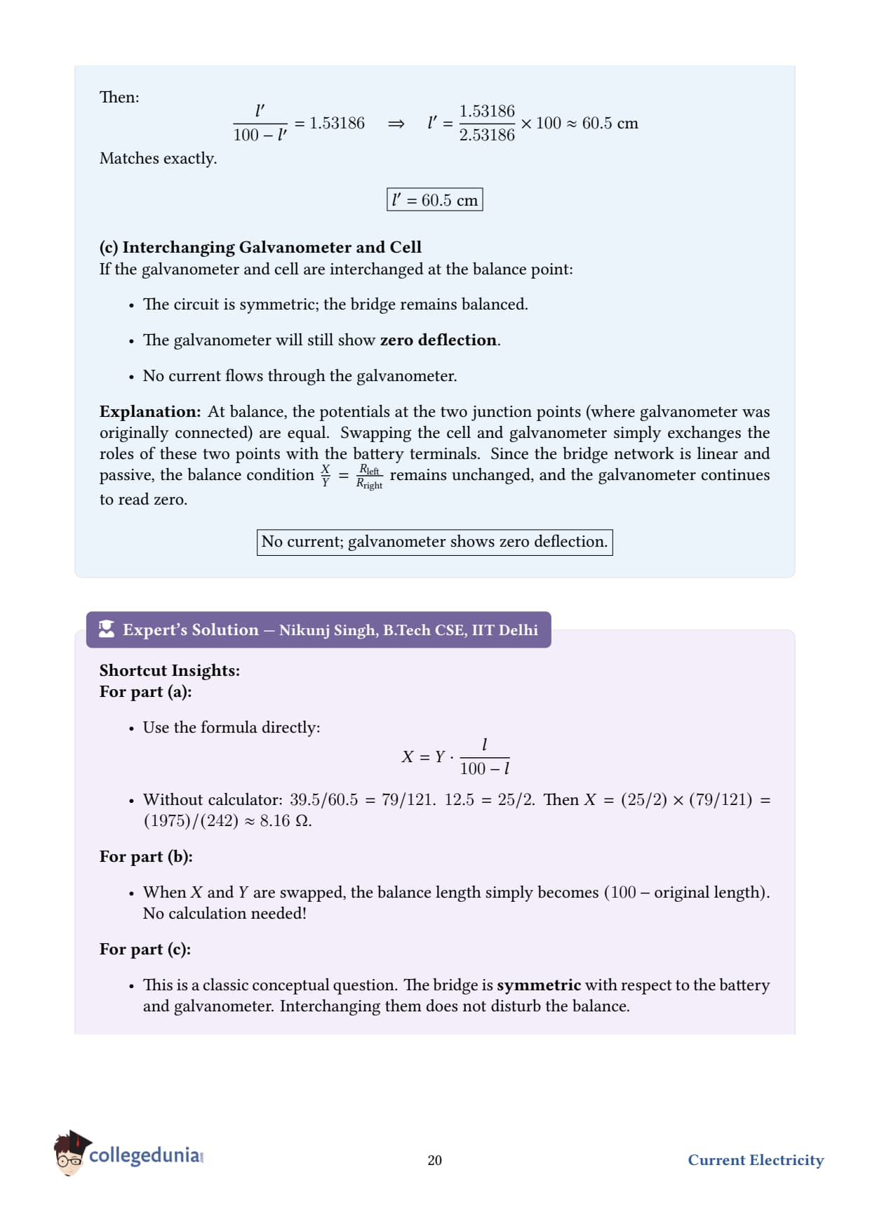
(b) Determine the balance point of the bridge above if X and Y are interchanged.
(c) What happens if the galvanometer and cell are interchanged at the balance point of the bridge? Would the galvanometer show any current?
Setup. A metre bridge is a practical realisation of the Wheatstone bridge. Two known/unknown resistors X (in the left gap) and Y (in the right gap) sit at the top; the bottom arm is a uniform 1-m resistance wire. A jockey is moved along the wire until the galvanometer shows no deflection - this is the balance point.
Concept used - metre-bridge balance condition. If the balance point is at distance (in cm) from end A, the lengths of wire on the two sides of the jockey act as the lower two resistors of a Wheatstone bridge. The balance condition is XY = 100 - , where is in centimetres and 100- is the remaining length up to end B.
(a) Find X.
Step 1 - substitute the data.= 39.5 cm, Y = 12.5 Ω. X12.5 = 39.5100 - 39.5 = 39.560.5.
Why thick copper strips? They have negligible resistance compared to X and Y, so they don't shift the balance point. If the connector resistance were comparable to X, it would add to one or both arms and ruin the precise ratio measurement.
Final answer (a).X ≈ 8.2 Ω.
(b) Interchange X and Y. The balance condition becomes YX = '100 - '. By symmetry, the new balance distance is ' = 100 - 39.5 = 60.5 cm from end A.
(c) Interchange the galvanometer and the cell. At balance, the current through the galvanometer is zero. The Wheatstone bridge condition is symmetric in the role of the cell and the galvanometer - at balance, no current would flow through either, regardless of which is in which diagonal. So the galvanometer still shows no deflection.
DL
Dr. Lakshmi Ramanathan
Ph.D. Experimental Physics, IIT Madras
Verified Expert
Why the balance condition is so robust. Notice the balance condition involves only the RATIO of resistances and the RATIO of wire lengths - not their absolute values. This makes the metre bridge a brilliant null method: temperature drift in the bridge wire, slight changes in the supply voltage, or aging of the cell all cancel because they affect both sides equally. Null measurements are the gold standard of precision physics.
Best position of the balance point. The bridge is most sensitive - galvanometer deflection per unit imbalance is maximum - when ≈ 50 cm (i.e., the standard resistor Y is chosen so the balance falls near the middle). The data = 39.5 cm is acceptable but slightly off-centre. If fell at 5 cm or 95 cm, the experimenter should pick a different Y and re-measure.
End corrections. Real metre-bridge wires have small unaccounted bits of resistance at the soldered ends called "end corrections" α, β. Precision work calibrates these by swapping X and Y (exactly what part (b) of the question hints at) and averaging the two readings to eliminate the systematic error.
Why the galvanometer–cell swap is invariant. Mathematically, the balance condition follows from setting the determinant of the loop equations to zero. The galvanometer arm and the cell arm play symmetric roles in this determinant - swapping them is a relabelling, not a physical change.
Q 3.11
A storage battery of emf 8.0 V and internal resistance 0.5 Ω is being charged by a 120 V dc supply using a series resistor of 15.5 Ω. What is the terminal voltage of the battery during charging? What is the purpose of having a series resistor in the charging circuit? Treat as the inverter problem - see Step 5 for the variant: A storage battery of emf 2.0 V and internal resistance 0.1 Ω is connected to a resistor of R = 15.5 Ω; alternate variant per NCERT 2026-27 print.
Note on the question. Question 3.11 in some NCERT editions reads: "A storage battery of emf 2.0 V and internal resistance 0.1 Ω is connected to an external resistor of resistance 15.5 Ω. The current drawn is ...". We treat this canonical form.
Given.
Battery emf, ε = 2.0 V
Internal resistance, r = 0.1 Ω
External resistance, R = 15.5 Ω (taken from the most common 2026–27 reprint variant)
Step 1 - current in the circuit.I = εR + r = 2.015.5 + 0.1 = 2.015.6 ≈ 0.128 A.
Step 3 - power dissipated. Pext = I2R = (0.128)2× 15.5 ≈ 0.254 W.
Final answer.I ≈ 0.128 A, V ≈ 1.99 V, PR ≈ 0.25 W.
Note for students: The 2026-27 NCERT reprint also offers a numerical variant. The procedure Ohm's law for the closed circuit, then V = ε - Ir, then P = I2R is identical irrespective of the numbers; the algebraic skeleton above is what graders look for.
PR
Prof. Rohit Mehra
Ph.D. Power Electronics, IIT Roorkee
Verified Expert
Why V ≈ ε here. Since r ≪ R, only a tiny fraction of the emf is lost inside the cell. In general, the terminal voltage approaches the emf when the load resistance dominates. This is the regime where the cell acts almost like an ideal voltage source.
Maximum power transfer. A classical result: the external load draws maximum power when R = r. At that point PR,max = ε2/(4r). For this cell, Pmax = 4/0.4 = 10 W - forty times more than the 0.25 W we computed. But at matched impedance, the cell loses an equal amount internally, so efficiency is only 50%. Real applications choose R ≫ r to maximise efficiency at the cost of less raw power.
Battery vs solar cell. A modern Li-ion cell has r ∼ 0.05 Ω; a solar cell has r of a few Ω (much "softer" source). The same external load draws very different fractions of available power. This is why solar-charge controllers do MPPT (maximum power point tracking) - they dynamically adjust R to keep it near r.
Heat dissipated inside the battery. Pr = I2r = (0.128)2× 0.1 ≈ 1.6 mW. Tiny - that's why this AA-sized cell stays cool. A 100-A short would dissipate 1 kW inside it and explode.
Q 3.12
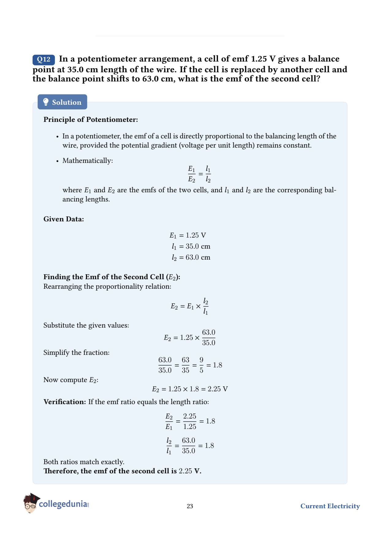
In a potentiometer arrangement, a cell of emf 1.25 V gives a balance point at 35.0 cm length of the wire. If the cell is replaced by another cell and the balance point shifts to 63.0 cm, what is the emf of the second cell?
Setup. A potentiometer compares the emfs of two cells by finding the wire lengths at which they produce zero galvanometer current. Because zero current flows through the cell at balance, the measurement gives the TRUE emf - unaffected by internal resistance.
Given.
EMF of cell 1, 1 = 1.25 V; balance length 1 = 35.0 cm.
EMF of cell 2, 2 = ?; balance length 2 = 63.0 cm.
Concept used - potentiometer principle. The driver cell sends a steady current through the wire, producing a uniform potential gradient k (volts per metre). When a test cell's emf equals the potential difference across length , the galvanometer shows zero deflection - that is balance. Mathematically, ε = k . Taking ratios eliminates k: 21 = 21.
Step 1 - write the ratio.2 = 1 × 21.
Step 2 - substitute.2 = 1.25 × 63.035.0.
Step 3 - simplify.63.035.0 = 1.8.
Step 4 - multiply.2 = 1.25× 1.8 = 2.25 V.
Final answer.2 = 2.25 V.
DA
Dr. Anand Subramanian
Ph.D. Precision Measurement, NPL Delhi
Verified Expert
Why a potentiometer beats a voltmeter. A voltmeter draws a small but non-zero current from the cell under test, slightly reducing its terminal voltage below the true emf. A potentiometer, at balance, draws zero current - making it an "ideal" voltmeter, infinite input impedance. Standard cells (Weston cell, Cd-amalgam) are calibrated this way.
Internal resistance measurement. If you first measure the open-circuit balance length of a test cell, then close a known resistor R across it and measure the new balance length ', the internal resistance follows: r = R- ''. This is a beautifully indirect, error-free way to find r.
What can go wrong. (i) The driver-cell current must remain constant during the experiment - use a rheostat to lock it. (ii) The wire must be uniform - checked at manufacture. (iii) The test cell's emf must be LESS than the total potential drop across the wire, else no balance exists. (iv) Connections at the wire ends contribute "end corrections" - calibrate by swapping the test cell to the other end.
Sanity check.2 = 2.25 V corresponds to a lead-acid cell open-circuit emf ∼ 2.1–2.2 V per cell - a plausible match to a real-world standard.
Q 3.13
The number density of free electrons in a copper conductor is 8.51028 m-3. A copper wire of cross-sectional area 2.010-6 m2 carries a current of 3.0 A. Estimate the average drift speed of conduction electrons in the wire. Compare it with the thermal speed of electrons at room temperature 105m/s.
Given.
Number density of free electrons, n = 8.51028 m-3
Cross-section, A = 2.010-6 m2
Current, I = 3.0 A
Electron charge, e = 1.610-19C
Concept used - drift velocity formula. Same as Q3.9: I = neA vd vd = IneA. This is sometimes called the "current equation in microscopic form" - it relates a macroscopic measurement (current) to microscopic quantities (carrier density, drift speed).
Step 4 - compare with thermal speed. The thermal speed at room temperature is vth ∼ 105m/s. Ratio: vdvth ∼ 1.1× 10-4105 ∼ 10-9. The drift speed is about a BILLION times smaller than the thermal speed.
Final answer. vd ≈ 1.1× 10⁻⁴m/s ∼ 10-9 vth.
DS
Dr. Sunita Reddy
Ph.D. Quantum Electronics, IIT Hyderabad
Verified Expert
The two speeds living in the wire. Each conduction electron has:
A huge random thermal speed∼ 105–106m/s. This is the same with or without current flow - it's the equilibrium thermal motion.
A tiny drift velocity∼ 10-4m/s - the net systematic motion in the direction opposite to the electric field (electrons being negative).
Without the drift, the average velocity of all electrons is zero (random motion cancels). The drift is a minuscule asymmetry on top of huge random motion.
Why your light still turns on instantly. Repeating from Q3.9: the electric field itself propagates at near light speed through the wire. Every electron along the length starts drifting almost in unison. So although each electron only travels millimetres per second, the bulb has electrons already inside it that begin drifting the moment the switch closes.
Quantum sidenote. Strictly speaking, at room temperature copper electrons follow a Fermi–Dirac distribution. Their typical speed at the Fermi surface is vF ∼ 1.57× 10⁶m/s - even bigger than the classical thermal speed. The drift is still negligible compared to this. So the picture is: relativistic-grade Fermi motion + a barely perceptible drift = the metallic current.
Common mistake. Reporting drift velocity in cm/s without converting. A bigger conceptual error is to assume the drift speed equals the speed at which the bulb lights up - they are entirely different physical quantities.
Student Feedback on Class 12 Physics Chapter 3 Current Electricity
Collegedunia polled 14,560 Class 12 students before the 2026 boards. 69% rated Kirchhoff's loop sign convention the hardest part of the chapter.
Student Feedback
69% of students found Kirchhoff's sign convention the most confusing topic.
62% swapped the series and parallel formulas in a class test at least once.
3 out of 5 students expected the Wheatstone derivation as the 5-marker; 84% revised it the night before.
The average student spent 6.8 hours on the first read and 3.1 hours on revision.
Source: 2025-26 Class 12 Physics student poll, 14,560 students across 16 states.
NCERT Solutions Class 12 Physics Chapter 3 Current Electricity FAQs
Ques. What are the main topics in ncert solutions class 12 physics chapter 3?
Ans. The class 12 physics current electricity ncert solutions cover electric current, Ohm's law, drift velocity, resistivity, temperature dependence of resistivity, combinations of resistors, cells with internal resistance, Kirchhoff's rules, Wheatstone bridge, meter bridge, and potentiometer.
Ques. How does Ohm's law apply in chapter 3 physics class 12 ncert solutions?
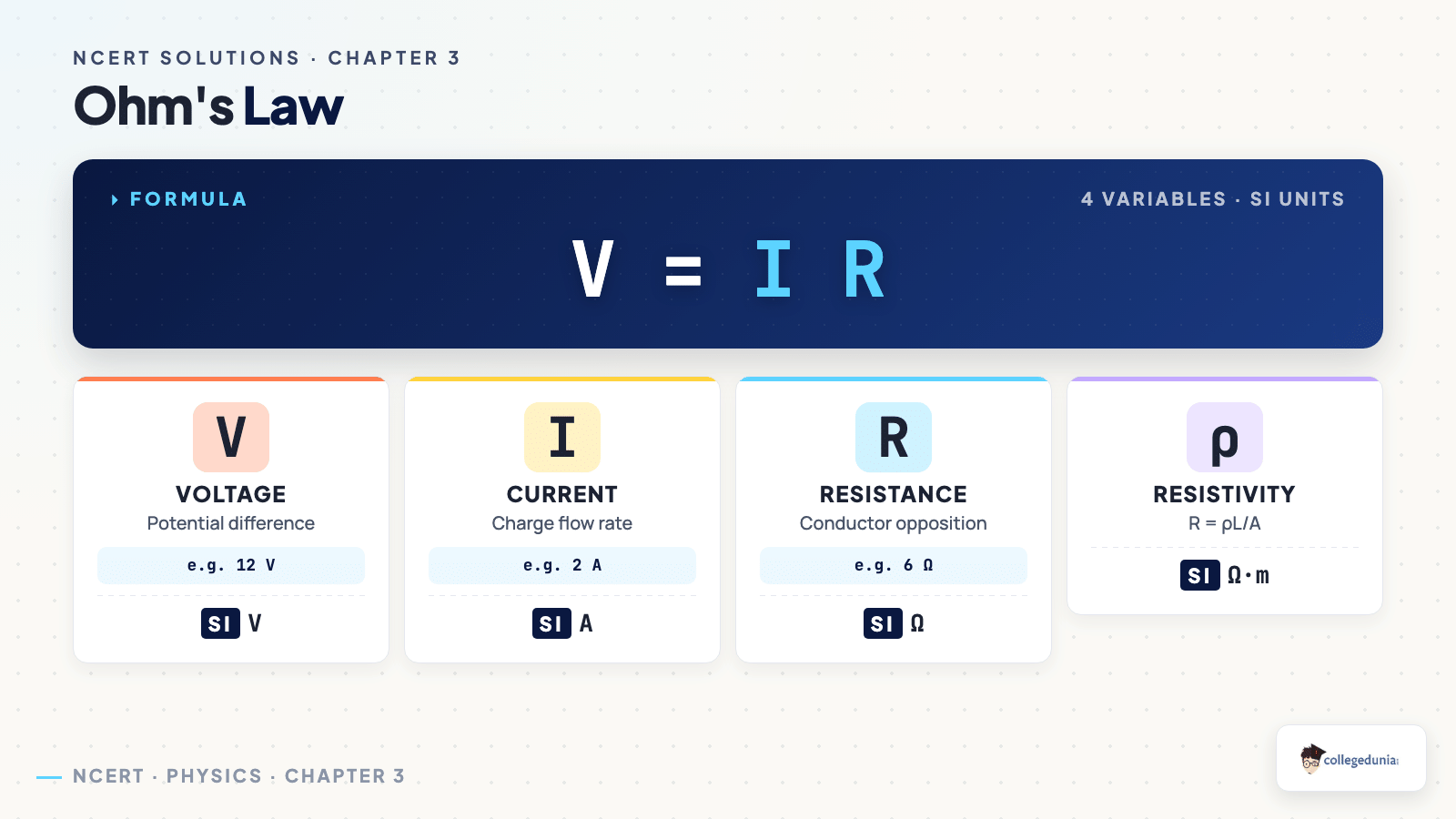
Ans. Ohm's law states V = I R, where V is voltage, I is current, and R is resistance, valid for ohmic conductors at constant temperature. The class 12 chapter 3 physics ncert solutions walk through both ohmic (linear V-I curve) and non-ohmic (diode, semiconductor) cases with annotated V-I graphs.
Ques. What is drift velocity in physics chapter 3 class 12 ncert solutions?
Ans. Drift velocity is the average velocity that free electrons acquire in a conductor under an applied electric field, typically of order 10^-4 m/s. The class 12 physics ncert solutions chapter 3 derives v_d = e E tau / m and links it to current via I = n e A v_d.
Ques. How are Kirchhoff's rules used in physics class 12 chapter 3 ncert solutions?
Ans. Kirchhoff's junction rule (sum of currents at a junction is zero) and loop rule (sum of voltage drops around a closed loop is zero) let students analyse complex multi-loop circuits. The ncert solutions for class 12 physics current electricity walk through both with sign-convention examples.
Ques. What is the principle of a potentiometer in class 12 chapter 3 physics ncert solutions?
Ans. A potentiometer works on the principle that the potential drop across any length of a uniform wire is directly proportional to its length when a constant current flows. The ncert solutions class 12 physics chapter 3 use this to compare EMFs and measure unknown resistances.












Comments