Physics Mentor, SRM Institute | Updated on - Jul 21, 2026
The NCERT Exemplar Class 12 Physics Chapter 6 Electromagnetic Induction Solutions cover all 28 problems with a clear Solution and an Expert Solution each. Every answer is checked against the last five years of CBSE Board, JEE Main and NEET papers. You can read or download the full PDF on this page for free.
CBSE Weightage: 4-6 marks
JEE Main Weightage: 2-3% (1-2 questions per paper)
NEET Weightage: 1-2 questions per year
Both downloads are free and match the 2026-27 NCERT syllabus.
The 28 problems cover Faraday's and Lenz's laws, motional EMF, self and mutual inductance, eddy currents and magnetic-field energy. The heavier MCQ-II and LA load sits on flux-rate and rod-on-rails setups.
What's Inside the NCERT Exemplar Class 12 Physics Solutions
Approximately 22 pages, the NCERT Exemplar Class 12 Physics Solutions carries every Exemplar problem with a clean Solution plus an Expert's Solution, inline TikZ figures for rail circuits and solenoid pairs, and the Exemplar's own numbering (6.1 to 6.28).
Quick Tip: Start with the four LA problems for JEE Advanced revision. They drill ε = -dΦ/dt under three geometries (rectangular loop, semicircular arc, solenoid).
How will the NCERT Exemplar Class 12 Physics Solutions on Collegedunia Help You?
Two-Layer Solution per Problem: A mark-earning Solution plus an Expert's Solution that names every concept invoked.
Inline Diagrams Where They Matter: Rail-and-rod, solenoid-pair, and flux-versus-time figures are redrawn, not skipped.
2026-27 NCERT Alignment: Every formula matches the latest NCERT print of Chapter 6.
JEE and NEET Cross-Tagging: Each Exemplar problem flags the exam year a near-identical setup reappeared.
MCQ-II carries the highest negative-marking risk because students lock in one correct option and skip the second. The verify-each-statement habit on Exemplar 6.5 is the fix.
Exemplar 6.5. A magnet is moved towards a closed coil. Which statements are correct?
(a) The coil face nearer the magnet acts as a like pole.
(b) Flux through the coil increases.
(c) Induced EMF depends only on speed, not magnet strength.
(d) Mechanical work against the magnetic force becomes electrical energy.
Reasoning. Lenz's law forces the near face to repel the magnet, so (a) holds. As the magnet approaches, flux rises, so (b) holds. ε = -dΦ/dt depends on both speed and magnet strength Φ ∝ B, so (c) is wrong. Work done against the retarding force becomes induced electrical energy, so (d) holds. Answers: (a), (b), (d).
Watch Out: Students often mark only (a) and (d). Verifying each statement catches (b) and rejects (c) cleanly.
Why Solving the Electromagnetic Induction Exemplar Sharpens Your JEE and NEET Edge
The textbook tests recall of Faraday-Lenz plus one-step motional EMF. The Exemplar chains two or three ideas: flux through a rotating loop, non-coaxial coupled coils, eddy currents in slotted plates. Most JEE Main and NEET items borrow their scaffold from Exemplar MCQ-II and SA.
Electromagnetic Induction Class 12th: Difficulty Step-Up from NCERT Textbook to Exemplar
The textbook stays one step from a solved examples the Exemplar shifts the geometry, adds a time-dependent field, or asks for the limit case.
Concept
Textbook
Exemplar Twist
Motional EMF
Rod on horizontal rails, constant B
Rotating rod about one end (Ex 6.18)
Flux change
Constant area, B(t)
Shrinking loop AND B(t) (Ex 6.20)
Self-inductance
Long solenoid plug-in
Variable-radius cross-section (Ex 6.24 variant)
Mutual inductance
Coaxial coils
Perpendicular coils: find M (Ex 6.11)
Lenz's law
Identify current direction
Predict ring temperature change (Ex 6.7)
Best Way to Use the Electromagnetic Induction Exemplar for JEE and NEET Prep
Solving 28 problems back-to-back is wrong for a 4-to-6-mark chapter. A type-budgeted pass tuned to target-exam works better.
Goal
Recommended pass
Time budget
CBSE Board 2026
All VSA + half of SA + 2 LA
2.5 h across 2 days
JEE Main 2026
All MCQ-I + MCQ-II + 4 SA
3 h, single sitting
NEET 2026
All MCQ-I + 3 MCQ-II + 2 VSA
2 h, after Moving Charges
Full revision
All 28 problems
5 to 6 h across 3 days
Exemplar-Specific Common Mistakes in Electromagnetic Induction
Sign of induced EMF: Dropping the negative in ε = -dΦ/dt breaks the direction.
Self vs mutual inductance: Students switch to M dI1/dt only when "two coils" is stated explicitly, missing implicit coupled setups.
Tilted loop flux: Forgetting the cosθ factor when the area-vector is not parallel to B.
Energy vs power: Stored energy is 12LI2;
instantaneous power is LI dI/dt. Mixing them costs 2 marks in LA.
Treating eddy currents as a separate phenomenon costs marks they are Lenz's law on a continuous conductor.
How Frequently Has Electromagnetic Induction Been Asked in CBSE, JEE and NEET (Top 3 Recurring Topics)
Three Exemplar sub-topics reappear disproportionately often across the last five years. The full year-wise PYQ trend is on the NCERT Solutions page.
Rank
Recurring topic
Recent appearances
1
Motional EMF on rod-and-rails
CBSE 2024, JEE Main 2025 Jan, NEET 2023
2
Solenoid self-inductance derivation
CBSE 2023, JEE Main 2024 Apr
3
Lenz's law direction with changing B
NEET 2025, JEE Main 2025, CBSE 2022
Electromagnetic Induction Top 5 Formulae for Exemplar Numericals
These five carry the bulk of SA and LA. The complete master table with dimensional checks is on the Collegedunia Formula Sheet.
All NCERT Exemplar Questions for Electromagnetic Induction with Step-by-Step Solutions
Every question of the NCERT Exemplar set for Class 12 Physics Chapter 6 Electromagnetic Induction is listed below with its full Solution and Expert Solution hidden inside collapsible tabs. Click Check Solution to reveal the step-by-step working; click Expert Solution for the expanded explanation.
Questions
Q 6.1
A square of side L metres lies in the x–y plane in a region, where the magnetic field is given by B=B0(2i+3j+4k) T, where B0 is constant. The magnitude of flux passing through the square is
(A) 2B0 L2Wb.
(B) 3B0 L2Wb.
(C) 4B0 L2Wb.
(D) √29 B0 L2Wb.
Correct option: (C)4B0 L2Wb.
Concept used. The magnetic flux through a flat surface of area
A in a uniform field B is the scalar product
B=B·A=BAcosθ, where θ is the angle
between B and the area vector A. The area vector is along
the outward normal of the surface, and its magnitude equals the area.
The square of side L lies in the x–y plane, so its
normal points along k. Hence
A = L2k.
Compute the dot product term by term:
aligned
B &= B·A
= B0(2i+3j+4k)·(L2k)
&= B0 L2[2(i·k)
+3(j·k)
+4(k·k)]
&= B0 L2[0+0+4]
= 4B0 L2 Wb.
aligned
Only the k component of B pierces the loop; the
i and j components lie in the plane of the
square and contribute zero flux. So (A) (which would give the
i coefficient), (B) (the j coefficient) and (D)
(which uses |B| as if the area vector were parallel to
B) are all wrong.
Option (C): B=4B0 L2Wb.
AM
Aarav Mehta
M.Sc. Physics, IIT Bombay
Verified Expert
Strategic angle. A loop only ``sees'' the field component along
its normal. Project the field onto n first; everything else is
arithmetic.
Loop normal: n=k. Component of B along
n is Bz=4B0.
Flux =Bz·(area)=4B0· L2=4B0 L2Wb.
Why this matters. The same trick handles every constant-field
flux problem: identify n, read off the parallel component, and
multiply by area.
Alternative – via |B|cosθ.
The angle between B and k satisfies
cosθ=B·k|B|=4√29,
so B=|B|Acosθ=B0√29· L2·
4√29=4B0L2Wb – exactly the same answer, just a
longer route. Choice (D) is the trap that drops the cosθ factor.
Unit cross-check.[B][A]=T·m2= Wb. Coefficient is
dimensionless, so 4B0L2 carries units of Wb as required.
Concept linkage. The very same projection trick reappears in
Chapter 1 (electric-flux through a tilted area) and in Chapter 4
(force on a current-carrying loop – only the perpendicular component
of B contributes to the torque). Flux is fundamentally a
``component-along-normal × area'' object.
B=4B0 L2Wb.
Q 6.2
A loop, made of straight edges, has six corners at A(0,0,0), B(L,0,0), C(L,L,0), D(0,L,0), E(0,L,L) and F(0,0,L). A magnetic field B=B0(i+k) T is present in the region. The flux passing through the loop ABCDEFA (in that order) is
(A) B0 L2Wb.
(B) 2B0 L2Wb.
(C) 2 B0 L2Wb.
(D) 4B0 L2Wb.
Correct option: (B)2B0 L2Wb.
Concept used. The loop is non-planar but still bounds a
surface. We split it into two planar squares and add their fluxes
Φ=B·A1+B·A2. The normals are
fixed by the order in which the corners are traversed, using the
right-hand rule (curl fingers along ABCD…, thumb gives n).
Sub-square 1:A(0,0,0)(L,0,0)(L,L,0)(0,L,0)
is a square in the x–y plane, traversed counter-clockwise
as seen from +z. So A1=L2k.
Sub-square 2:D(0,L,0)(0,L,L)(0,0,L)(0,0,0)
is a square in the y–z plane (i.e. the x=0 plane).
Traversed in this order it is counter-clockwise as seen from
+x. So A2=L2i.
Strategic angle. Use the fact that flux depends only on the
boundary, not on the chosen surface. Pick the easiest surface –
two squares meeting along AD.
Square in xy-plane bounded by ABCD: normal k, area
L2, gives B0 L2.
Square in yz-plane bounded by ADEF: normal i, area
L2, gives B0 L2.
Sum: 2B0 L2Wb.
Why this matters. Flux through any cap with the same boundary
is the same – a direct consequence of ∇·B=0.
Alternative – shrink the boundary.
You can replace the L-shaped loop with the flat triangle that has the
same edge sequence projected onto each face. Because
B=B0(i+k) has equalx- and z-components,
the two square-projections each carry B0L2, giving the same total
2B0L2 – a nice consistency check.
Sign discipline.
The corner order A
fixes both normals to point outward along +k and +i
respectively. Had the problem said FEDCBA, both normals would flip
and the answer would be -2B0L2. Marks are often lost on this.
Concept linkage. The independence of flux on the chosen cap is
exactly why we can apply Faraday's law to any convenient surface –
critical when handling solenoids and toroids later in this chapter.
B=2B0 L2Wb.
Q 6.3
A cylindrical bar magnet is rotated about its axis (Fig. 6.1). A wire is connected from the axis and is made to touch the cylindrical surface through a contact. Then
(A) a direct current flows in the ammeter A.
(B) no current flows through the ammeter A.
(C) an alternating sinusoidal current flows through the ammeter A with a time period T=2π/ω.
(D) a time-varying non-sinusoidal current flows through the ammeter A. [2pt]
Fig. 6.1, NCERT Exemplar Class 12 Physics, Chapter 6.
Correct option: (B) No current flows through the ammeter.
Concept used. Faraday's law says ε=-dB/dt. A
current can flow only if the magnetic flux linked with the closed
circuit changes with time.
Identify the closed circuit: axis wire → ammeter →
cylindrical surface contact, with the bar magnet itself acting
as one ``arm''.
As the magnet rotates about its own axis, its geometry and its
magnetic field configuration are unchanged at every instant –
the field has cylindrical symmetry about the rotation axis.
Therefore the flux B linked with the circuit is
constant in time:
dBdt=0 ε=0.
With ε=0, Ohm's law gives I=ε/R=0.
Hence no current flows, ruling out (A), (C) and (D).
Option (B): No current; rotating an axially symmetric magnet about its own symmetry axis does not change the flux.
RV
Rohit Verma
M.Sc. Physics, University of Delhi
Verified Expert
Strategic angle. Spin-symmetry test – if rotating the source
leaves it looking identical, the field pattern is time-independent and
no e.m.f. can appear.
The bar magnet is cylindrically symmetric about its axis.
Rotation about that axis is a symmetry of the system.
A symmetry of the source cannot change the flux through any
fixed circuit – so dΦ/dt=0 and ε=0.
Why this matters. A real homopolar generator needs the wire
itself to move through the field, not just the magnet to spin; this
question is its negative counterpart.
Alternative – motional emf check.
Try to compute a motional e.m.f. ∫(v×B)
along the axis wire: v=0 for points on the axis (no
translation), and along the radial brush contact the magnet's surface
also moves with velocity tangential, but the closed loop is stationary
in the lab. The conductor (wire + ammeter) does not move at all, so
the line integral vanishes element-by-element.
Common pitfall. Students often confuse this setup with the
Faraday disc (rotating conducting disc in a fixed field), where
a real DC e.m.f. does appear. The difference: in the Faraday disc the
conductor rotates through the field. Here the conductor is
fixed and only the field source spins – but the field pattern
itself is rotation-invariant, so nothing changes.
Concept linkage. ``A field that is invariant under a continuous
symmetry of its source cannot induce an e.m.f.'' generalises the
``dΦ/dt=0'' criterion to arbitrary geometries.
No current; symmetry forbids any change in flux.
Q 6.4
There are two coils A and B as shown in Fig. 6.2. A current starts flowing in B as shown, when A is moved towards B and stops when A stops moving. The current in A is counter-clockwise. B is kept stationary when A moves. We can infer that
(A) there is a constant current in the clockwise direction in A.
(B) there is a varying current in A.
(C) there is no current in A.
(D) there is a constant current in the counter-clockwise direction in A. [2pt]
Fig. 6.2, NCERT Exemplar Class 12 Physics, Chapter 6.
Correct option: (D) A constant current in the counter-clockwise direction in A.
Concept used. An e.m.f. is induced in coil B only when the
flux through B changes. The flux through B depends on (i) the
current in A and (ii) the separation between A and B.
The current in B exists only while A is moving and
stops the instant A stops. Therefore the source of the
changing flux is the motion of A, not the current variation
in A itself. This rules out (B): if the current in A were
varying, B would show a current even with A at rest.
Since B does carry a current while A is moving, the flux
through B must change with separation, which requires the
current in A to be non-zero. This rules out (C).
The question explicitly tells us the current in A is
counter-clockwise (as seen in the figure). Hence (A), which
specifies clockwise, is wrong.
Combining: the current in A is steady (so motion alone causes
the flux change) and counter-clockwise.
Option (D): constant counter-clockwise current in coil A.
SP
Sneha Patel
B.Tech Electrical Engineering, IIT Gandhinagar
Verified Expert
Strategic angle. Decouple the two causes of flux change –
current variation vs. geometric motion – and test each against the
data.
``B has current iff A moves'' ⇒ flux change is
purely geometric, not current-driven ⇒IA is
constant.
``Current in A is counter-clockwise (given)''. So IA is
constant and counter-clockwise.
Why this matters. This is exactly the principle of a
transformer's primary at DC – moving a DC-energised coil mimics an
AC primary for the secondary.
Alternative – mutual-inductance view.
If B=M(t) IA, then B=-dBdt=
-dMdtIA-MdIAdt.
The data (B exists ⇔A moves) tells us
only the first term contributes: dM/dt≠ 0 (because separation is
changing) but dIA/dt=0 (because IA is steady). This is exactly
the algebraic statement of step 1.
Common pitfall – mistaking B for IA.
Some students see ``current in B is in some direction'' and conclude
that IA must be in that same direction. The current in B is the
induced one and its sign is set by Lenz's law – it has no
direct correspondence with IA. The question states IA's
direction outright; that's what fixes (A) vs. (D).
Concept linkage. The same logic underlies wireless-charging
pads – a DC-energised coil produces no e.m.f. in the receiver
unless the geometry (separation, alignment, or current) changes.
Constant counter-clockwise current in A.
Q 6.5
Same as problem 6.4 except the coil A is made to rotate about a vertical axis (Fig. 6.3). No current flows in B if A is at rest. The current in coil A, when the current in B (at t=0) is counter-clockwise and the coil A is as shown at this instant (t=0), is
(A) constant current clockwise.
(B) varying current clockwise.
(C) varying current counter-clockwise.
(D) constant current counter-clockwise. [2pt]
Fig. 6.3, NCERT Exemplar Class 12 Physics, Chapter 6.
Correct option: (A) Constant current in the clockwise direction in A.
Concept used. As in 6.4, the e.m.f. in B is driven by the
change in flux through B. Here the change is produced by Arotating, not translating.
``No current in B if A is at rest'' ⇒ the
current in A does not vary on its own. So IA is constant
– rules out (B) and (C).
As A rotates, the flux it sends through B oscillates,
producing an alternating e.m.f. in B. The given direction in
B at t=0 is counter-clockwise.
By Lenz's law, the induced current in B opposes the change
that produced it. For B's current to be counter-clockwise at
this instant, the magnetic flux from A through B must be
decreasing in the direction pointing from A into B.
Working backwards through the right-hand rule, this requires
the steady current in A to circulate in the clockwise
sense (as viewed from B). So (A) is correct, (D) is wrong.
Option (A): constant clockwise current in A.
AM
Aarav Mehta
M.Sc. Physics, IIT Bombay
Verified Expert
Strategic angle. Two pieces of evidence: (i) only motion drives
B's current, so IA is steady; (ii) Lenz's law converts the given
direction in B at t=0 into a direction in A.
``At rest ⇒ no current in B'' fixes IA=const.
Sign analysis via Lenz's law on the instantaneous geometry of
Fig. 6.3 reverses the sense from B to A⇒
clockwise in A.
Why this matters. A rotating DC-energised coil is the simplest
AC generator – the same mechanism powers commercial alternators.
Alternative – flux-sign book-keeping.
At t=0 let nB point out of the page. If IB is
counter-clockwise (right-hand rule) then the induced field at
B's centre is along +nB. By Lenz's law the induced field
opposes the change, so the flux through B from A must be
decreasing along +nB. The only way this happens with
IA steady is that A's axis is rotating away from coincidence
with nB, with IA producing field along -nB at the
instant shown – which (right-hand rule applied to A) means IA
runs clockwise.
Numerical cross-check.
If B(t)=M0 IAcos(ω t) with M0>0 and IA>0, then
B=-B=+M0 IA(ω t). At t=0+
this is positive in our convention, so the current in B flows in the
positive sense (counter-clockwise as drawn) – matching the data with
IA steady.
Concept linkage. This is literally how a household ceiling fan
generates back-EMF when momentarily disconnected – a DC-energised
rotor in a stator coil acts as an instantaneous AC source.
Constant clockwise current in A.
Q 6.6
The self inductance L of a solenoid of length l and area of cross-section A, with a fixed number of turns N, increases as
(A) l and A increase.
(B) l decreases and A increases.
(C) l increases and A decreases.
(D) both l and A decrease.
Correct option: (B)l decreases and A increases.
Concept used. The self-inductance of a long air-core solenoid
of length l, cross-sectional area A and N total turns is
L=0 N2Al,
derived from Φ=N BA with B=0(N/l)I.
Read off the dependence: with N fixed and 0 a constant,
L∝ A/l.
Therefore L increases iff A increases and/or ldecreases.
Check each option against L∝ A/l:
(A): both up ⇒ depends on which dominates;
not guaranteed to increase.
(B): A↑, l↓⇒L↑.
(C): A↓, l↑⇒L↓.
(D): both down ⇒ indeterminate.
Option (B): L increases when l decreases and A increases.
PS
Priya Sharma
M.Sc. Physics, IISc Bengaluru
Verified Expert
Strategic angle. Memorise the ratio A/l for a solenoid; the
question is then pure proportionality.
L=0 N2A/l, so the ``increase'' directions are
A↑ or l↓.
Only option (B) does both unambiguously.
Why this matters. Real inductors increase L by packing more
turns into a shorter, fatter coil – exactly the (B) recipe.
Alternative – per-unit-length form.
With n=N/l (turns per metre), B=0 nI and the flux linkage is
NΦ=N· BA=0N2lAI, so
L=0N2Al. The same formula, derived from
Φ=LI, makes the A/l dependence obvious.
Numerical cross-check. For N=1000, A=10-3m2,
l=0.5 m: L=4π10-7· 106· 10-30.5
≈ 2.5 mH. Halving l to 0.25 m doubles it to 5.0 mH;
doubling A to 210-3m2 doubles it again to
10 mH – consistent with (B).
Common pitfall. Many students try option (A) thinking
``bigger means more inductance''. But a longer coil with the same N
reduces n=N/l and so weakens B, dropping Φper turn
faster than the extra length helps. The dependence is on A/l, not
on volume Al.
Concept linkage. The energy stored is
U=12 LI2=120B2· Al, so the energy
density u=B2/(20) is set by B alone (Section 6.10 of NCERT).
L and volume together encode the same physics.
l↓, A↑⇒L↑.
Q 6.7
A metal plate is getting heated. It can be because
(A) a direct current is passing through the plate.
(B) it is placed in a time-varying magnetic field.
(C) it is placed in a space-varying magnetic field, but does not vary with time.
(D) a current (either direct or alternating) is passing through the plate.
Correct options: (A), (B), (D).
Concept used. A metal plate dissipates energy (I2R
Joule heating, or eddy-current heating) whenever there is a current in
it. The current may be supplied externally or induced via Faraday's
law ε=-dB/dt.
(A) A direct current dissipates P=I2R.
(B) A time-varying B produces dΦ/dt≠ 0
and hence eddy currents in the plate – these dissipate as
heat.
(C) A space-varying but static field has
∂B/∂ t=0 everywhere, so no e.m.f. is
induced and (for a stationary plate) no eddy currents flow –
no Joule heat. 55
(D) Any current, DC or AC, dissipates I2R (or
Irms2R).
(A), (B), (D).
RV
Rohit Verma
M.Sc. Physics, University of Delhi
Verified Expert
Strategic angle. Pin down the two energy sources – an
externally driven current ((A) and (D)) and induced eddy currents
((B)). Static spatial variation alone does no work, ruling out (C).
External current ⇒I2R heating: (A), (D).
Time-varying B⇒ eddy currents ⇒
heat: (B).
Static field (even if non-uniform in space) ⇒ no
e.m.f. ⇒ (C) is false.
Why this matters. Eddy-current heating is the principle of
induction cooktops – a time-varying field heats the pan without
contact.
Alternative – energy bookkeeping.
Joule heat per unit volume is j2/σ where j is the current
density and σ the conductivity. So heating requires
j≠ 0 somewhere inside the plate. The only ways to make j≠ 0
are: connect a battery (DC) or supply oscillation (AC) – options (A)
and (D); or drive eddy currents with ∂B/∂ t≠ 0
– option (B). A purely spatial B(r) that does not change in
time leaves ∂B/∂ t=0 everywhere, hence
E=0 in the plate's rest frame and j=σE=0.
Why (C) is wrong, in detail.
``Space-varying but constant in time'' is the field of a permanent
magnet held still next to a stationary plate. No part of the plate
sees a changing flux, so ∮E=0 around every
small loop. No e.m.f., no eddy currents, no heating.
Concept linkage. Eddy currents are not just heaters –
they're also brakes. In electromagnetic braking of trains a copper
plate moves through a static field; the motion of the conductor
turns the static field into a time-varying one in the conductor's
frame, dissipating kinetic energy as heat. (C) becomes a heating
mechanism the moment the plate is allowed to move.
(A), (B), (D).
Q 6.8
An e.m.f. is produced in a coil, which is not connected to an external voltage source. This can be due to
(A) the coil being in a time-varying magnetic field.
(B) the coil moving in a time-varying magnetic field.
(C) the coil moving in a constant magnetic field.
(D) the coil is stationary in an external spatially varying magnetic field, which does not change with time.
Correct options: (A), (B), (C).
Concept used. Faraday's law ε=-dB/dt. The
flux B=∫BA changes if either B
changes with time, or the loop moves/changes shape so that the surface
integral changes.
(A) Stationary coil, B varies in time
⇒dΦ/dt≠ 0⇒ε≠ 0.
(B) Coil moves andB varies in time –
both contributions are present, ε≠ 0.
(C) Coil moves through a static B that is
non-uniform across the coil (or the coil is reoriented) –
motional e.m.f. ε=∮(v×B)l≠ 0.
(D) Coil stationary in a static (but spatially
varying) field ⇒ no time-change of Φ⇒ε=0. 55
(A), (B), (C).
SP
Sneha Patel
B.Tech Electrical Engineering, IIT Gandhinagar
Verified Expert
Strategic angle. Total dΦ/dt has two pieces – ``B
changes'' and ``loop moves''. As long as at least one is non-zero,
ε is non-zero.
(A) B changes only: yes.
(B) both change: yes.
(C) loop moves only: yes (motional e.m.f.).
(D) nothing changes: no.
Why this matters. A generator (case C) and a transformer
(case A) are two sides of the same Faraday-law coin.
Alternative – the Leibniz decomposition.
The total time-derivative of Φ=SBA for a
moving surface S(t) obeys
dΦdt=
S∂B∂ tA
- ∂ S(v×B).
The first term is the ``transformer'' piece (option A); the second is
the ``motional'' piece (option C); option B has both. Option D
zeros both terms.
Why (D) really fails.
``Spatially varying but time-independent'' B has
∂B/∂ t=0. A stationary loop has v=0, so
both terms vanish identically. Even if B varies wildly in space,
no induced e.m.f. appears – Φ is a fixed number set by the
spatial integral.
Concept linkage. The two terms map onto two physical pictures
we learn separately: transformers (term 1) and AC generators / linear
generators / electromagnetic guns (term 2). Faraday's law unifies them.
(A), (B), (C).
Q 6.9
The mutual inductance M12 of coil 1 with respect to coil 2
(A) increases when they are brought nearer.
(B) depends on the current passing through the coils.
(C) increases when one of them is rotated about an axis.
(D) is the same as M21 of coil 2 with respect to coil 1.
Correct options: (A), (D).
Concept used. Mutual inductance is a purely geometric
quantity defined by
12=M12 I2,
where 12 is the flux through coil 1 due to current I2 in
coil 2. Reciprocity theorem: M12=M21.
(A) Bringing coils nearer increases the flux of one
through the other for the same current, so M increases.
(B)M is defined as Φ/I – the ratio is
independent of I. Doubling the current doubles Φ,
leaving M unchanged. So (B) is false. 55
(C) Rotation could either increase or decrease the
overlap of flux lines – e.g. rotating one coil through
90∘ relative to the other reduces M. The statement
``increases when rotated'' is not generally true. 55
(D) The reciprocity theorem M12=M21 follows
from the symmetry of Maxwell's equations in source-free
regions.
(A), (D).
AM
Aarav Mehta
M.Sc. Physics, IIT Bombay
Verified Expert
Strategic angle. Test each option against the defining
relation M12=12/I2 and the reciprocity M12=M21.
Closer coils ⇒ more flux linkage ⇒
(A) true.
M independent of current ⇒ (B) false.
Rotation can decrease coupling ⇒ (C) not universally
true.
Reciprocity ⇒ (D) true.
Why this matters. Reciprocity (D) lets us choose the easier of
the two flux integrals when computing M.
Alternative – vector-potential view.M12 can be written as Neumann's double-line integral
M12=04πC1C2d12|r1-r2|.
The integrand is manifestly symmetric under 1↔ 2,
which proves M12=M21 on the spot (option D). And distance
|r1-r2| appears in the denominator, so reducing it
(bringing coils closer) increases M (option A).
Why (B) is firmly false.M is a geometric coupling coefficient, not a function of I.
This is the same statement as ``capacitance does not depend on the
voltage stored''.
Why (C) is conditional.
Starting from 90∘ misalignment (M≈ 0) and rotating
toward coaxial alignment does increase M. The blanket
statement ``rotation increases M'' is too broad – it depends on
the starting orientation. So (C) is not universally true and is
counted wrong.
Numerical cross-check.
For two coaxial circular coils of radii a and b (b≪ a)
separated by z: M=0π a2b22(a2+z2)3/2.
Independent of I. Decreases as z grows – consistent with (A).
Concept linkage. Reciprocity (D) is the same principle that
gives equal mutual capacitance in a network – a deep result from
linearity of Maxwell's equations.
(A), (D).
Q 6.10
A circular coil expands radially in a region of magnetic field and no electromotive force is produced in the coil. This can be because
(A) the magnetic field is constant.
(B) the magnetic field is in the same plane as the circular coil and it may or may not vary.
(C) the magnetic field has a perpendicular (to the plane of the coil) component whose magnitude is decreasing suitably.
(D) there is a constant magnetic field in the perpendicular (to the plane of the coil) direction.
Correct options: (B), (C).
Concept used. For zero induced e.m.f., dΦ/dt=0, where
Φ=BAcosθ uses only the field component perpendicular to the
loop.
(A) ``Field constant'' alone is not enough; if it is
also perpendicular to the coil, the expanding area changes
Φ and an e.m.f. appears. So (A) is incomplete. 55
(B) If B lies in the plane of the coil, then
BA=0, so Φ=0 regardless of how the
area changes or how B varies in time. Hence
ε=0.
(C) If B⊥ decreases at exactly the rate at
which the area increases (so that B⊥A=const),
then dΦ/dt=d(B⊥A)/dt=0 and ε=0.
(D) Constant perpendicular field with expanding area
gives Φ=B⊥π r2(t) which is increasing, hence
ε≠ 0. 55
(B), (C).
PS
Priya Sharma
M.Sc. Physics, IISc Bengaluru
Verified Expert
Strategic angle. Write Φ=B⊥A and force the
product to be constant (or zero).
B⊥=0 identically ⇒Φ=0⇒
(B).
B⊥(t)A(t)=const⇒dΦ/dt=0⇒ (C).
Why this matters. A vanishing time-derivative of a product is
not the same as either factor being constant – a subtlety that
eliminates (A) and (D).
Alternative – product-rule cross-check.dΦdt=B⊥A+B⊥A. For this to vanish
in case (C), the two terms must cancel: B⊥/B⊥=
-A/A, i.e. B⊥ must decrease at the same logarithmic
rate the area grows. Calling r(t) the loop radius,
B⊥B⊥=-2rr. So B⊥∝
1/r2 keeps Φ constant – a very specific tuning.
Why (D) really fails.
With B constant and perpendicular, Φ=B(π r2). As r
grows, dΦdt=2π Brr≠ 0 unless r=0
(loop is not expanding). The problem states it is expanding,
so (D) generates an e.m.f. – it cannot be one of the zero-emf cases.
Concept linkage.
This setup is the inverse of a homopolar generator: instead of the
e.m.f. driving current, here we force a special B(r,t) to keep the
e.m.f. at zero. The same idea is used in superconducting flux pumps
to maintain constant flux against a changing area.
(B), (C).
Q 6.11
Consider a magnet surrounded by a wire with an on/off switch S (Fig. 6.4). If the switch is thrown from the off position (open circuit) to the on position (closed circuit), will a current flow in the circuit? Explain. [2pt]
Fig. 6.4, NCERT Exemplar Class 12 Physics, Chapter 6.
Concept used. Faraday's law: an e.m.f. is induced in a loop
only when the magnetic flux through that loop changes with
time. Closing a switch makes the circuit conducting; it does
not change the field of the (stationary) magnet.
The bar magnet is at rest and its field is therefore static at
every point. The wire loop is also at rest.
Before the switch is closed, the loop is open – but the
magnet's flux through the surface bounded by the wire still
has some definite value 0. After the switch is closed,
the same field configuration gives the same 0. Hence
dBdt=0 ε=0.
With ε=0, no current flows even though the loop is
now closed and conducting.
No – merely closing the switch does not change the flux, so no current flows. A current would appear only if the magnet (or the loop) starts moving, or the field is altered after the switch is closed.
RV
Rohit Verma
M.Sc. Physics, University of Delhi
Verified Expert
Strategic angle. Separate the topology of the circuit (open
vs. closed) from the time-derivative of the flux. Only the latter
drives an e.m.f.
Closing the switch changes resistance from ∞ to a finite
value but not B.
dΦ/dt=0⇒ε=0⇒ no
current.
Alternative – circuit analogy.
Think of the magnet's flux 0 as a fixed reservoir. Faraday's law
acts like a generator that needs Φ to change; if the
reservoir level is constant, the generator outputs zero volts no
matter whether you've connected a load (closed circuit) or left it
open. Closing S only attaches the load.
Common pitfall. ``Closing the switch should send a current
into the loop because flux now passes through the closed loop.'' Wrong
on two counts: (i) flux through the wire-bounded surface existed
before too (Faraday's law cares about dΦ/dt, not about loop
``closedness''); (ii) the magnet has not moved, so Φ never
changes. Currents need a time-varying flux, not just any flux.
Concept linkage. If immediately after closing S you started
pulling the magnet away (or pushed it in), then dΦ/dt≠ 0 and
a current would appear. This is exactly Faraday's original 1831
experiment.
No current flows on closing the switch.
Q 6.12
A wire in the form of a tightly wound solenoid is connected to a DC source, and carries a current. If the coil is stretched so that there are gaps between successive elements of the spiral coil, will the current increase or decrease? Explain.
Concept used. For a tightly wound solenoid, the flux linked
with the coil is Φ=LI with L=0 n2Vsol and
n=N/l is the turn density. When the geometry is changed, Lenz's
law dictates the direction of the induced response.
Stretching the coil creates gaps between successive turns.
Magnetic field lines now leak out through these gaps,
so the flux Φ linked with the solenoid decreases.
By Lenz's law, the induced e.m.f. opposes this decrease in
flux – it acts in the same direction as the source e.m.f.,
so the net e.m.f. driving the circuit increases.
Equivalently, the inductance L=0 n2Vsol
falls (because n=N/l falls when l rises), so the inductive
reactance / back-e.m.f. drops and more current can flow.
Therefore the current increases once the coil is
stretched.
I=εras flux leakage reduces opposing back-e.m.f.
The current increases, because stretching the coil makes flux leak through the gaps; by Lenz's law the induced e.m.f. aids the source, and the reduced inductance lets more current flow.
SP
Sneha Patel
B.Tech Electrical Engineering, IIT Gandhinagar
Verified Expert
Strategic angle. Apply Lenz's law to the change in flux
caused by stretching. The induced response always opposes the
change, here a decrease in linked flux.
Gaps open between turns ⇒ flux Φ leaks
through the gaps and drops.
Induced e.m.f. opposes this fall ⇒ aids the
source ⇒ current I rises.
Also n=N/l falls ⇒L=0 n2V falls
⇒ inductive reactance falls ⇒ more
current.
Quantitative flavour.
Take a solenoid with N turns, length l0, radius r. Initial
n0=N/l0 and 0=0 n0I π r2N links the coil.
After stretching to length l1>l0, n1=N/l10, 1<0="" ind="-dΦ/dt" (i.="" at="" during="" e.m.f.="" induced="" is="" same="" so="" stretching="" the="">0\) – adding to the source
e.m.f. and momentarily boosting the current.
Why the ``r=ρ/A so current falls'' argument is
not what NCERT wants.
A real solenoid's wire length changes only marginally on stretching
(the helix simply un-tilts); the dominant electromagnetic effect is
the flux leakage through the newly opened gaps. The exemplar's
official answer therefore rests on Lenz's law, not on a small
ohmic correction.
Concept linkage. The same logic explains why a coil with
ferromagnetic core (large r) carries less DC than the air-core
case during transient core insertion: in both problems we
follow the flux change and apply Lenz's law.
Current increases (flux leakage ⇒ Lenz-aiding e.m.f.).
Q 6.13
A solenoid is connected to a battery so that a steady current flows through it. If an iron core is inserted into the solenoid, will the current increase or decrease? Explain.
Concept used. Inserting a ferromagnetic core multiplies the
flux through the solenoid by a factor r≫ 1:
Φ=r0nIA· N. Lenz's law says that the induced
e.m.f. opposes this increase in flux.
Before insertion, the flux through the solenoid is
0=0nIA· N.
As the iron core slides in, r rises from 1 to a large
value (r∼ 103–104 for soft iron), so the
flux Φ=r0 rises sharply.
By Lenz's law, the induced e.m.f. opposes this rise
in flux – it acts against the source e.m.f. and
therefore drives the current down.
Equivalently, L=r0 n2V has grown by a factor
r, so the inductive reactance / opposing back-e.m.f.
is much larger – the steady current that the source can
push through the inductor decreases.
The current decreases, because the iron core multiplies the flux by r; the induced e.m.f. opposes the source (Lenz's law) and the larger inductance lets less current through.
AM
Aarav Mehta
M.Sc. Physics, IIT Bombay
Verified Expert
Strategic angle. Track the flux: any change in r
re-routes flux lines, and Lenz's law fixes the sign of the response.
Iron core enters ⇒r rises ⇒
flux Φ rises.
Lenz: induced e.m.f. opposes the rise ⇒ opposes
the source ⇒Idecreases.
Quantitatively L has grown by factor r, so the
back-e.m.f. is large during insertion and the steady current
settles at a smaller value than before.
Quantitative back-e.m.f.
With L=r0 n2V, inserting the core in time
ins gives dLdt∼(r-1)L0ins.
The back-e.m.f. is then approximately
back=IdLdt∼
I(r-1)L0ins.
For r∼ 5000 (soft iron), L0∼ 1 mH, I∼ 0.1 A
and ins∼ 1 s, we get
back∼ 0.5 V – enough to drop the current
substantially.
Common pitfall. ``Flux Φ=LI increases, so I must
increase too.'' Wrong: the inserted core makes L much larger, and
the source e.m.f. cannot maintain the previous current against the
larger inductance. The induced e.m.f. opposing the source forces
I down.
Concept linkage. Iron-cored chokes in power supplies use
exactly this effect to limit current; without the core, the same
coil would pass a larger current and saturate the load.
Current decreases (Lenz-opposing e.m.f. during r↑).
Q 6.14
Consider a metal ring kept on top of a fixed solenoid (say on a cardboard) (Fig. 6.5). The centre of the ring coincides with the axis of the solenoid. If the current is suddenly switched on, the metal ring jumps up. Explain. [2pt]
Fig. 6.5, NCERT Exemplar Class 12 Physics, Chapter 6.
Concept used. Lenz's law: the induced current in a conductor
opposes the change of flux producing it. Two co-axial current loops
attract if they carry parallel currents and repel if anti-parallel.
Switching the solenoid on causes its axial flux through the
ring to grow from zero. By Lenz's law the induced current in
the ring flows in the direction that produces a flux
opposing the growth – i.e. anti-parallel to the
solenoid's field on the axis.
The induced ring current is therefore in the opposite sense to
the solenoid current at the ring's location. Two coaxial loops
with anti-parallel currents repel each other.
Hence the ring experiences an upward repulsive force; if this
exceeds its weight, the ring jumps up.
Switching on the solenoid induces a ring current opposing the growing flux. The induced current is anti-parallel to the solenoid's, so the two repel and the ring is thrown upward.
PS
Priya Sharma
M.Sc. Physics, IISc Bengaluru
Verified Expert
Strategic angle. Treat the ring as the secondary of a
transformer and apply Lenz's law to read off the direction, then use
the parallel/anti-parallel loop force rule.
Flux growth ⇒ induced current opposes
⇒ anti-parallel to solenoid.
Anti-parallel coaxial loops repel ⇒ ring jumps up.
Alternative – pole picture.
At the top of the solenoid, the field lines emerge upward (say); this
is a magnetic N-pole. By Lenz's law, the induced current in the ring
must produce a flux opposing the growing upward flux. The
ring therefore presents a N-pole on its bottom face – and two N-poles
facing each other repel. Result: the ring is launched upward, exactly
as observed.
Energy budget.
Where does the ring's kinetic energy come from? From the source
e.m.f. driving the solenoid current. Power ε Isol
goes partly to Isol2R heating, partly to building the
magnetic-field energy, and partly to mechanical work on the ring.
Conservation of energy is rigorously maintained.
Concept linkage. The jumping ring is a stock demonstration in
Indian physics labs. A more violent version – a copper ring on an iron
core with an AC coil – can shoot the ring several metres. Same Lenz
mechanism, just at 50 Hz.
Repulsion from induced anti-parallel ring current.
Q 6.15
Consider a metal ring kept (supported by a cardboard) on top of a fixed solenoid carrying a current I (see Fig. 6.5). The centre of the ring coincides with the axis of the solenoid. If the current in the solenoid is switched off, what will happen to the ring? [2pt]
Fig. 6.5, NCERT Exemplar Class 12 Physics, Chapter 6.
Concept used. Same as 6.14 – Lenz's law plus the
parallel/anti-parallel force rule for coaxial loops.
Switching the current off causes the solenoid's axial flux
through the ring to decrease from a non-zero value
toward zero. By Lenz's law the induced current in the ring
flows so as to maintain the existing flux – i.e.
parallel to the solenoid's original current.
Two coaxial loops with parallel currents attract.
Therefore the ring is pulled down toward the (now de-energising)
solenoid.
However, the attractive impulse lasts only as long as the
current is decaying. For a typical sudden switch-off this is
very brief, so in practice the ring is pulled down
momentarily and may also be observed to leap slightly upward
first if the magnetic pressure pulse is large enough.
On switching off, Lenz's law makes the induced ring current parallel to the solenoid current. The two loops attract and the ring is pulled down toward the solenoid (and may oscillate briefly before coming to rest).
RV
Rohit Verma
M.Sc. Physics, University of Delhi
Verified Expert
Strategic angle. Mirror image of 6.14: ``flux decreasing'' is
opposed by an induced current that supports the existing flux.
Flux falling ⇒ induced ring current parallel to
solenoid.
Parallel coaxial currents attract ⇒ ring pulled
down.
Alternative – pole picture.
While energised, the top of the solenoid presented (say) a N-pole.
Switching the solenoid off does not change the ring's pole instantly,
but during the decay the induced current in the ring tries to
preserve the existing flux through itself. The bottom face of
the ring therefore behaves like a S-pole and the top face of the
solenoid (now decaying) still has residual N-character. S meets N
⇒ attraction ⇒ ring snaps downward.
Why the effect is brief.
The attractive impulse lasts only while dIsol/dt≠ 0. For
a typical mechanical switch this is microseconds, and the ring
acquires a small downward momentum but is then in free fall under
gravity. The net observed behaviour: a small ``thud'' onto the
cardboard.
Concept linkage.
Compare with 6.14: switching on gave a sustained jump because
the current rise lasted milliseconds and the magnetic pressure
built up; switching off gives a much shorter pulse because the
inductor's stored energy drops faster (an arc may form across the
switch, draining the energy quickly).
Ring is attracted downward.
Q 6.16
Consider a metallic pipe with an inner radius of 1 cm. If a cylindrical bar magnet of radius 0.8 cm is dropped through the pipe, it takes more time to come down than it takes for a similar unmagnetised cylindrical iron bar dropped through the metallic pipe. Explain.
Concept used. As a magnet falls through a conducting pipe,
its motion produces a changing flux through every horizontal cross-
section of the pipe. By Faraday's and Lenz's laws, eddy currents are
induced that oppose the change of flux – producing a magnetic
braking (retarding) force on the magnet.
Magnetised bar: as it falls, the flux through a ring of
the pipe just below the magnet grows, while the flux through
a ring just above it falls. Both rings develop eddy currents
whose magnetic fields oppose the motion of the magnet (Lenz's
law) – the ring below behaves like a like pole, the ring
above like an unlike pole. The result is an upward
force on the magnet, reducing its acceleration well below g.
Unmagnetised iron bar: carries no permanent magnetic
moment, so no significant changing flux is set up in the
pipe as it falls. No eddy currents, no retarding magnetic
force; the bar accelerates under gravity essentially as in
free fall (apart from negligible air drag).
Hence the magnetised bar takes longer to traverse the
pipe than the unmagnetised one. The effect can be vivid enough
that a strong neodymium magnet drifts down a copper pipe at
nearly constant terminal velocity.
Eddy currents induced in the pipe by the falling magnet exert an upward retarding force (Lenz's law). An unmagnetised iron bar produces no such currents, so it falls faster.
SP
Sneha Patel
B.Tech Electrical Engineering, IIT Gandhinagar
Verified Expert
Strategic angle. Compare flux change: a moving magnet drives
dΦ/dt in the pipe; a moving piece of iron does not.
Magnet falling ⇒ eddy currents in pipe ⇒
Lenz-law retarding force ⇒ slower descent.
Iron bar falling ⇒ no net flux change ⇒
no eddy currents ⇒ near-free fall.
Terminal-velocity estimate.
At terminal velocity vt the magnetic braking force equals weight:
Fbr(vt)=mg. A simple scaling argument gives
Fbr≈α Beff2vRpipe,
where Beff is the field at the pipe wall and
Rpipe is the eddy-current loop resistance. So
vt≈mgRpipeα Beff2. For a
strong NdFeB magnet (Beff∼ 0.5 T) in a copper pipe of
1 cm wall, vt is typically a few cm/s – demonstrably slow to the
eye.
Why an unmagnetised iron bar still feels some drag.
Iron is ferromagnetic, so it does become weakly magnetised by stray
fields and by the Earth's field. But the moment is tiny compared to a
permanent magnet's, so the flux change as it falls through the pipe
is also tiny – the eddy-current braking force is negligible, and
gravity dominates.
Concept linkage.
Electromagnetic braking on rails – some high-speed trains use a strong
magnet hovering over the iron rail; eddy currents in the rail provide
contactless braking. The pipe-and-magnet demo is the laboratory
analogue.
Magnet is slowed by eddy-current braking; iron bar is not.
Q 6.17
A magnetic field in a certain region is given by B=B0cos(ω t) k and a coil of radius a with resistance R is placed in the x–y plane with its centre at the origin in the magnetic field (see Fig. 6.6). Find the magnitude and direction of the current at (a,0,0) at t=π/(2ω), t=π/ω and t=3π/(2ω). [2pt]
Fig. 6.6, NCERT Exemplar Class 12 Physics, Chapter 6.
Concept used. For a flat loop of area A in a uniform
field B(t), B=B·A. Faraday's law gives
ε=-dB/dt and Ohm's law I=ε/R. The
sign of I, with A chosen along +k, follows the
right-hand rule – positive I flows counter-clockwise as seen from
+k.
Induced e.m.f. and current:
ε=-dBdt
=-π a2B0·(-ω t)
=π a2B0 ω t, I(t)=εR
=π a2B0 ωRsinω t.
Let I0≡π a2B0ω/R.
Evaluate at the three instants:
t=π2ω: ω t=π/2, sinω t=+1.
I=+I0, i.e. counter-clockwise (along +j at the point (a,0,0)).
t=πω: ω t=π, sinω t=0.
I=0.
t=3π2ω: ω t=3π/2, sinω t=-1.
I=-I0, i.e. clockwise (along -j at the point (a,0,0)).
I(t)=π a2B0ωRsinω t. At t=π/(2ω), I=+π a2B0ωR along +j; at t=π/ω, I=0; at t=3π/(2ω), I=π a2B0ωR along -j.
AM
Aarav Mehta
M.Sc. Physics, IIT Bombay
Verified Expert
Strategic angle. Differentiate the cosine, plug in the three
phases, attach directions via the right-hand rule.
Φ=π a2B0cosω t⇒ε=π a2B0ω t.
At the three quarter-periods sinω t=1,0,-1⇒I=+I0,0,-I0 with directions as above.
Direction check via Lenz at t=π/(2ω).
At this instant B=B0cos(π/2)k=0, but
Ḃ=-B0(π/2)k=-B0ωk – the
flux through the loop is decreasing along +k. Lenz's
law says the induced current must produce a flux supporting +k.
By the right-hand rule, that current flows counter-clockwise as
viewed from +k – at (a,0,0) this points along +j,
matching the sign found above.
Numerical sanity check.
Pick B0=0.1 T, a=0.05 m, ω=100 rad/s, R=10 Ω:
I0=π(0.05)2(0.1)(100)/10=7.85× 10-4A
≈ 0.78 mA. A meter would register this comfortably.
Concept linkage.
This is a textbook AC dynamo problem – a sinusoidal field through a
fixed loop produces a sinusoidal current that is π/2 out of phase
with the field (current is maximum when B is maximum, which is
when B is zero). The same phase relation governs every transformer
secondary.
I0=π a2B0ω/R; signs follow sinω t.
Q 6.18
Consider a closed loop C in a magnetic field (Fig. 6.7). The flux passing through the loop is defined by choosing a surface whose edge coincides with the loop and using the formula φ=B1A1+B2A2+…. Now if we choose two different surfaces S1 and S2 having C as their edge, would we get the same answer for flux? Justify your answer. [2pt]
Fig. 6.7, NCERT Exemplar Class 12 Physics, Chapter 6.
Concept used. Gauss's law for magnetism: ∇·B=0
everywhere, equivalently ∂ VBA=0
for any closed surface V. There are no magnetic monopoles.
Take both surfaces S1 and S2 with the loop C as their
common boundary. Together they enclose a closed volume.
Choosing outward normals on this closed surface, Gauss's law
gives
∮(BA)=
S1BA1 out
+S2BA2 out=0.
The outward normal of S2 is opposite to the orientation we
would give it if we wanted both surfaces oriented consistently
with the boundary loop C (right-hand rule). Flipping that
sign,
S1BA1
=S2BA2.
Therefore the flux through C is the same for any cap, S1
or S2.
Yes – because ∇·B=0, the flux through any surface bounded by the loop C depends only on C, not on the surface chosen. So S1 and S2 give identical fluxes.
PS
Priya Sharma
M.Sc. Physics, IISc Bengaluru
Verified Expert
Strategic angle. ``Two caps on one boundary'' = closed
surface; apply ∮BA=0.
S1∪ S2 closes the surface; net outward flux is zero.
Sign-flipping one surface to match the boundary gives equal
fluxes through S1 and S2.
Why this matters. The same reasoning is what allows you to
choose ``any convenient surface'' when applying Faraday's law.
Alternative – vector-potential argument.
Since ∇·B=0 globally, there is a vector potential
A with B=∇×A. By Stokes' theorem,
SBS=
S(∇×A)S=
∂ SA.
The last expression depends only on the boundary ∂ S=C, not
on S. So Φ is a property of C alone – exactly what we wanted
to show.
Where this fails. If there were a magnetic monopole inside
the volume enclosed by S1∪ S2, then ∮BA=0 qm≠ 0 and the two cap fluxes would differ by
0 qm. The non-observation of any flux discrepancy in
electromagnetic-induction experiments is one of the most precise
upper bounds on monopole abundance.
Concept linkage.
This freedom is what lets us draw a Faraday-law solenoid problem with
a ``cup-shaped surface'' rather than a flat disc – crucial when the
flat disc cuts the solenoid axis at an awkward place.
Same answer; flux depends only on the boundary.
Q 6.19
Find the current in the wire for the configuration shown in Fig. 6.8. Wire PQ has negligible resistance. B, the magnetic field, is coming out of the paper. θ is a fixed angle made by PQ travelling smoothly over two conducting parallel wires separated by a distance d. [2pt]
Fig. 6.8, NCERT Exemplar Class 12 Physics, Chapter 6.
Concept used. Motional e.m.f.: for a straight conductor of
length eff sliding with velocity v in a uniform
field B perpendicular to the rails,
ε=Beff v⊥.
Here eff is the component of the conductor that ``cuts''
the field lines as it moves.
The slider PQ makes angle θ with the rails, so the
length of the sliding conductor between the two rails is
PQ=dsinθ.
Only the component of PQ perpendicular to its velocity v
contributes to the area-sweep rate. That component is the rail-
separation d itself (the rails are parallel to v).
Equivalently, the area swept per unit time is dv.
Hence the induced e.m.f. is
ε=BdAdt=Bdv.
With PQ having negligible resistance and total resistance
R (the rest of the circuit), Ohm's law gives
I=εR=BdvR.
I=BdvR (independent of the angle θ, because the rate at which area is swept depends only on the rail separation d and the slider speed v).
RV
Rohit Verma
M.Sc. Physics, University of Delhi
Verified Expert
Strategic angle. Forget the angle; compute dA/dt directly.
In time dt, the slider moves v dt along the rails; area
swept is dA=d· v dt.
ε=B dA/dt=Bdv; I=Bdv/R.
Why this matters. The slanted slider does not change
ε – it just stretches the slider's physical length without
adding any flux-cutting power.
Alternative – motional-emf integral.
Compute ε=PQ(v×B)
along the slanted rod. With v=vx, B=Bz, we get
v×B=-vBy. Parameterise the rod from P to
Q as r(s)=s(cosθx+sinθy),
0≤ s≤ d/sinθ, so d=(cosθx+
sinθy) ds. The dot product is
(-vB)(sinθ) ds, integrating to
(-vBsinθ)·(d/sinθ)=-vBd. Magnitude ε=vBd
– same answer, θ cancels.
Why the angle cancels.
The slanted rod has more wire-length contributing per unit
swept area, but each unit of wire moves through less
field-cutting (only the perpendicular component of velocity matters).
The two effects cancel and only B, d, v survive.
Concept linkage.
This Bdv formula is the universal motional-emf result – it underlies
linear induction generators (used in some MAGLEV systems) and is
identical to the e.m.f. in a rectangular sliding-bar setup at
θ=90∘.
I=Bdv/R.
Q 6.20
A (current vs time) graph of the current passing through a solenoid is shown in Fig. 6.9. For which time is the back electromotive force (u) a maximum? If the back e.m.f. at t=3 s is e, find the back e.m.f. at t=7 s, 15 s and 40 s. OA, AB and BC are straight-line segments. [2pt]
Fig. 6.9, NCERT Exemplar Class 12 Physics, Chapter 6.
Concept used. The back-e.m.f. of a solenoid of self-inductance
L is
u=-LdIdt.
Its magnitude is proportional to the slope of the I–t graph.
For piecewise-linear segments, the slope is constant on each segment.
Read slopes from Fig. 6.9:
OA (between t=0 and t=5 s): I rises from 0
to 1 A. Slope mOA=(1-0)/(5-0)=+0.2 A/s.
AB (between t=5 and t=10 s): I falls from
+1 A to -2 A. Slope mAB=(-2-1)/(10-5)=-0.6 A/s.
BC (between t=10 and t=30 s): I rises from
-2 A to 0 A. Slope mBC=(0-(-2))/(30-10)=+0.1 A/s.
For t>30 s, I=0 (constant); slope =0.
Maximum |u| occurs where |dI/dt| is maximum – on segment
AB, 5 s.< li="">
Given u(t=3 s)=e. Here t=3 is on OA, slope
+0.2 A/s. So in magnitude
e=L (0.2).
Thus L=e/0.2=5e (in units where 1 A/s gives
1 V).
Compute back-e.m.f. at the requested instants:
t=7 s on AB: |u|=L |mAB|=5e× 0.6=3e.
Slope is negative, so u(t=7)=-(-3e)=+3e. Magnitude
3e, with sign opposite to the OA case.
t=15 s on BC: |u|=L |mBC|=5e× 0.1=0.5e.
Slope positive, same sign as OA, so u(t=15)=-0.5e.
(Sign relative to u(3)=e is the same as OA's slope
sign, so u(t=15)=e· 0.1/0.2=0.5e with the
same sign as e.)
t=40 s: I is constant, so dI/dt=0 and u=0.
The back-e.m.f. is maximum on segment AB (between t=5 and t=10 s). With u(3)=e we get u(7)=-3e, u(15)=+0.5e and u(40)=0. (The sign of u tracks the sign of -dI/dt, but the magnitudes are the ones to memorise.)
SP
Sneha Patel
B.Tech Electrical Engineering, IIT Gandhinagar
Verified Expert
Strategic angle. The back-e.m.f. is proportional to slope –
read the three slopes, scale them by |u|/slope at t=3 s.
Slopes: OA=0.2, AB=-0.6, BC=0.1, beyond C =0 A/s.
|u| is 3× on AB, 0.5× on BC, and 0 for
t>30, relative to |u(3 s)|=e.
Max at AB. u(7):|3e|, u(15):0.5e, u(40)=0 (signs as
in the main solution).
Alternative – ratio approach.
Since u∝ dI/dt and L is fixed, u(t)u(3)=
m(t)mOA on any segment. So
u(7)/e=mAB/mOA=-0.6/0.2=-3;
u(15)/e=mBC/mOA=0.1/0.2=0.5;
u(40)/e=0/0.2=0. No need to compute L explicitly.
Why the sign matters.
Back-e.m.f. opposes the change in current. On OA, I is
rising, so u opposes the rise (sign convention chosen so this is
``positive e''). On AB, I is falling, so u acts to oppose
the fall – its sign reverses, hence u(7)=-3e. Sign tracking
is what distinguishes a competent answer from a copy of formulas.
Concept linkage.
This is exactly the principle behind flyback diodes across
inductors and relay coils: when the supply current is suddenly cut
(AB-like steep drop), the inductor generates a huge L |dI/dt|
voltage that would damage transistors – the flyback diode shunts
the current safely.
|u| max on AB; |u(7)|=3e, |u(15)|=0.5e, u(40)=0.
Q 6.21
There are two coils A and B separated by some distance. If a current of 2 A flows through A, a magnetic flux of 10-2 Wb passes through B (no current through B). If no current passes through A and a current of 1 A passes through B, what is the flux through A?
Concept used. The mutual inductance is symmetric:
M12=M21≡ M. The flux through one coil due to current in
the other is Φ=MI.
From the first scenario, with IA=2 A and B=10-2 Wb,
M=BIA=10-2 Wb2 A
=5× 10⁻³H.
By reciprocity, the same M governs the reverse case. With
IB=1 A,
A=M IB=(5× 10⁻³H)(1 A)
=5× 10⁻³ Wb.
A=5× 10⁻³Wb (using M12=M21=5 mH).
AM
Aarav Mehta
M.Sc. Physics, IIT Bombay
Verified Expert
Strategic angle. The two scenarios share a single number M.
Extract M from one, plug into the other.
M=10-2/2=5 mH.
A=M· 1=5 mWb.
Why reciprocity is non-trivial.
A naive expectation would be that flux ``transferred'' from a bigger
coil to a smaller one differs from the reverse. The reciprocity
theorem (M12=M21) says no – this remarkable fact follows
directly from ∇·B=0 and the linearity of Maxwell's
equations.
Unit cross-check.M in henries = Wb/A. So 5× 10⁻³Wb/A =5 mH.
A=M IB has units H·A = Wb.
What if the coils had iron in between?
A high-r medium between the coils would multiplyM
by roughly r – the same flux-amplification mechanism that
gives transformers their high coupling coefficient k≈ 1.
Concept linkage.
Reciprocity also implies that a single coupling coefficient k
controls both ``A-to-B'' and ``B-to-A'' transfer, justifying
the ideal-transformer ratio V2/V1=N2/N1 used in Chapter 7.
A=5 mWb.
Q 6.22
A magnetic field B=B0sin(ω t) k covers a large region where a wire AB slides smoothly over two parallel conductors separated by a distance d (Fig. 6.10). The wires are in the x–y plane. The wire AB (of length d) has resistance R and the parallel wires have negligible resistance. If AB is moving with velocity v, what is the current in the circuit? What is the force needed to keep the wire moving at constant velocity? [2pt]
Fig. 6.10, NCERT Exemplar Class 12 Physics, Chapter 6.
Concept used. Total induced e.m.f.
ε=-dB/dt has two contributions here: (i) the field
B(t) itself changes in time, and (ii) the area of the circuit
changes because AB moves. We compute Φ, differentiate, then use
Ohm's law and the magnetic force on a current-carrying conductor.
Let x(t)=vt be the position of the slider measured from some
reference. The area of the circuit is A(t)=dx(t)=dvt
(taking x=0 at t=0). With A along k,
B(t)=B0sin(ω t)· dvt.
Differentiate with the product rule:
dBdt=B0dv[ω tcos(ω t)+sin(ω t)].
Force on the slider: the magnetic force on a current-carrying
rod of length d in field B(t) has magnitude
Fmag=B(t) I(t) d. To keep AB at constant
velocity, an external agent must apply
Fext(t)=B0sin(ω t)· I(t)· d
=B02 d2vRsin(ω t)[ω tcos(ω t)+sin(ω t)].
Strategic angle. Recognise the two flux-change contributions
and combine via the product rule.
Flux Φ=B(t)A(t)=B0sinω t· dvt.
dΦ/dt gives ε, then I=ε/R and the
agent force F=BId as above.
Alternative decomposition.
Split the e.m.f. into transformer + motional pieces:
ε=
-B(t)· A(t)transformer
-B(t)·A(t)motional
=-B0(ω t)· dvt-B0sin(ω t)· dv.
Factor: ε=-B0dv[ω tcosω t+sinω t] – same
answer. The split shows clearly that both mechanisms contribute and
the formula is just the Faraday law written two ways.
Limiting checks.
(a) Constant field (ω→ 0, B=B0): ε=-B0dv,
F=B02d2v/R – the standard sliding-rod result.
(b) Stationary rod (v→ 0): both ε and F vanish,
which is wrong! Actually with v=0, the area A= const but flux
Φ=B0sinω t· A0 still varies in time, so
ε≠ 0. The expression in the answer assumed A=dvt
starts at A=0 – so the limit v→ 0 collapses the loop too.
A more general start with A(0)=A0>0 would handle this case.
Concept linkage.
This problem is a microcosm of all AC-generator analysis: the
secondary's e.m.f. has a ``transformer'' part (changing B) and
a ``motional'' part (moving rotor). Real generators harness both.
I and F as in the main solution.
Q 6.23
A conducting wire XY of mass m and negligible resistance slides smoothly on two parallel conducting wires as shown in Fig. 6.11. The closed circuit has a resistance R due to AC. AB and CD are perfect conductors. There is a magnetic field B=B(t) k.
(i) Write down the equation for the acceleration of the wire XY.
(ii) If B is independent of time, obtain v(t), assuming v(0)=u0.
(iii) For (ii), show that the decrease in kinetic energy of XY equals the heat lost in R. [2pt]
Fig. 6.11, NCERT Exemplar Class 12 Physics, Chapter 6.
Concept used. Motional e.m.f. ε=Bv on a
sliding rod; Newton's second law on the rod under the magnetic
braking force F=BI; energy balance using Pdiss=I2R.
Let be the length of XY between the rails (the figure
labels this l) and x(t) its position along the rails, with
v=dx/dt. The flux through the circuit is
Φ=B(t) x(t), so
ε=-dΦdt
=-[B(t) x+B(t) v].
Current: I=ε/R.
Magnetic force on XY: F=IB(t), directed opposite to
v (Lenz's law). Newton's second law:
mdvdt
=-B(t)[B(t)x+B(t)v]R. iThis is the equation of motion.
(ii) Constant B: put B=0, B(t)=B. Equation
(i) becomes
mdvdt=-B22Rv.
Separate variables and integrate:
u0vdv'v'=-B22mR0tdt', ln(v/u0)=-B22mRt, v(t)=u0 e-B22t/(mR).
(iii) Energy balance. Power dissipated in R:
Pdiss=I2R=(BvR)2R
=B22v2R.
Rate of change of kinetic energy of XY:
dKdt=ddt(12mv2)
=mvdvdt
=mv(-B22mRv)
=-B22v2R.
So dK/dt+Pdiss=0 at every instant, i.e. the rate
of loss of kinetic energy equals the rate of Joule heating in
R. Integrating from 0 to ∞:
12m u02=0∞Pdiss dt.
(i) mx=-B(t)[B(t)x+B(t)x]/R. (ii) v(t)=u0 e-B22t/(mR). (iii) dK/dt=-I2R at every instant, so the total kinetic energy lost equals the total heat developed in R.
RV
Rohit Verma
M.Sc. Physics, University of Delhi
Verified Expert
Strategic angle. The rod is a one-dimensional damped system
mv=-γ v with γ=B22/R. Exponential decay
follows.
EOM mv+γ v=0 with γ=B22/R.
Solution v=u0 e-γ t/m.
Power dissipated I2R=γ v2=-dK/dt confirms
0∞ I2R dt=12m u02.
Why this matters. Electromagnetic braking on a rail is the
direct DC analogue of viscous drag.
Time-constant interpretation.
The decay time is τ=mR/(B22). Larger R⇒
weaker eddy current ⇒ weaker braking ⇒ longer
τ. Stronger B or longer rod ⇒ faster decay. This
is exactly the design knob for an electromagnetic brake – engineers
choose the rail resistance and magnet strength to set τ for
target stopping distance.
Energy as integral.0∞ I2R dt=0∞B22v2Rdt.
Substituting v=u0 e-t/τ:
0∞B22u02Re-2t/τdt
=B22u02R·τ2
=B22u02R·mR2B22
=12m u02. Exactly the initial kinetic energy –
zero leakage.
Common pitfall (time-varying B case).
For part (i) with non-zero B the EOM has two damping
terms and an extra forcing through B(t)x. Students often
drop the B(t)x term, but it represents the transformer e.m.f.
which can drive the rod even when stationary.
v=u0 e-B22t/(mR); lost KE = heat in R.
Q 6.24
ODBAC is a fixed rectangular conductor of negligible resistance (CO is not connected) and OP is a conductor which rotates clockwise with an angular velocity ω (Fig. 6.12). The entire system is in a uniform magnetic field B whose direction is along the normal to the surface of the rectangular conductor ABDC. The conductor OP is in electric contact with ABDC. The rotating conductor has a resistance of λ per unit length. Find the current in the rotating conductor as it rotates by 180∘. [2pt]
Fig. 6.12, NCERT Exemplar Class 12 Physics, Chapter 6.
Concept used. Rotational motional e.m.f. across a uniform rod
rotating in a perpendicular uniform B:
ε=12Bω L2,
where L is the active length (from the pivot to the contact point).
The current is then I=ε/r, with r the resistance of
the section of OP in the circuit.
Label the geometry from Fig. 6.12: the rectangle has sides
l (vertical, from AC to DB on each side of O) and total
horizontal length 2l (from C to D through O). The rod
OP has length L and is pivoted at O (centre of CD).
For 0θ≤π/4, the rod OP first sweeps the
rectangle OBA on the right; its end P touches the side
BD at a distance from O equal to OP=l/cosθ.
For π/4θ≤ 3π/4, P touches the upper side
AB at OP=l/sinθ (so OP=l when
θ=π/2).
For 3π/4θ≤π, P touches the left side AC
at OP=-l/cosθ=l/|cosθ|.
The e.m.f. developed across the full rod between O
and its end P is ε=12BωOP2
(the standard rotating-rod result). The portion of the rod in
the circuit has length OP, so its resistance is
r=λ OP.
Current at angle θ:
I(θ)=εr
=12BωOP2λOP
=BωOP2λ.
Substituting the three pieces:
0θ≤π/4:
I=Bω l2θ.
π/4θ≤ 3π/4:
I=Bω l2θ.
3π/4θ≤π:
I=Bω l2λ|cosθ|.
The direction follows from the right-hand rule applied to
v×B on a segment of the rod and the
circuit's closure through the rectangle.
Piecewise current in the rotating conductor: I=Bω l2θ for 0θ≤π/4 and for 3π/4θ≤π (using |cosθ| in the second range), and I=Bω l2θ for π/4θ≤ 3π/4.
SP
Sneha Patel
B.Tech Electrical Engineering, IIT Gandhinagar
Verified Expert
Strategic angle. The e.m.f. of a uniformly rotating rod and
its resistance both scale with the same length OP; the
OP2/OP ratio leaves a single power of length in
the answer.
ε=12BωOP2,
r=λOP, so I=BωOP/(2λ).
Express OP piecewise as above to get I(θ) on
each side.
Derivation of ε=12Bω L2.
A point on the rod at distance r from the pivot has speed v=ω r.
The motional-e.m.f. contribution from an element dr is
dε=Bvr (dr/r)=Bω r dr. Integrate from r=0 to
r=L: ε=Bω0Lr dr=12Bω L2.
Why current diverges at θ=π/4 junctions.
As θ→π/4-, OP=l/cosθ→ l2; at the
junction the formula switches to l/sinθ=l2. The two
branches give the same OP at the corner – I is continuous,
not divergent. (A pure formula like 1/cosθ diverges at
π/2, but the physical rod never reaches a corner with
cosθ→ 0 while still using that branch.)
Concept linkage.
This is essentially a disc generator with a piecewise-linear ``rim''.
A circular rim (the Faraday disc) gives constant OP=L,
constant I. The rectangular boundary modulates the contact length
and so modulates the output current.
Diagram-based reasoning.
The current peaks at θ=π/4,3π/4 where OP=l2
is largest, and dips to its minimum at θ=π/2 (where
OP=l). The output is therefore a non-sinusoidal but periodic
waveform with period π.
I(θ)=BωOP/(2λ) with OP as given.
Q 6.25
Consider an infinitely long wire carrying a current I(t), with dIdt=λ= constant. Find the current produced in the rectangular loop of wire ABCD if its resistance is R (Fig. 6.13). [2pt]
Fig. 6.13, NCERT Exemplar Class 12 Physics, Chapter 6.
Concept used. Field of an infinite straight wire at distance
r: B(r)=0I/(2π r), directed by the right-hand rule. The
flux through the rectangle is found by integrating across its width.
Let the rectangle ABCD have side l parallel to the wire and
extend from r=x0 to r=x0+x perpendicular to the wire.
A strip of width dr at distance r has area l dr and
flux contribution
dΦ=B(r) l dr=0I(t)2π rl dr.
Integrate from r=x0 to r=x0+x:
Φ(t)=0I(t) l2πx0x0+xdrr
=0I(t) l2πln(x0+xx0).
Differentiate, using dI/dt=λ:
dΦdt=0l λ2πln(x0+xx0).
Induced e.m.f. and current (magnitudes):
ε=dΦdt=0l λ2πln(x0+xx0), Iloop=εR
=0l λ2π R
ln(x0+xx0).
Iloop=0l λ2π R ln(x0+xx0).
AM
Aarav Mehta
M.Sc. Physics, IIT Bombay
Verified Expert
Strategic angle. The wire's 1/r field forces an integration
across the loop; the time derivative pulls λ out front.
Strip integration ⇒Φ(t)∝ I(t)ln[(x0+x)/x0].
Differentiate, divide by R.
Why a logarithm appears.
Field B(r)∝ 1/r integrated across a strip gives
∫ dr/r=ln r. Whenever you see a long straight wire and a
parallel rectangle, expect a logarithm in the flux – it's the
signature of the 1/r falloff.
Sanity check via direction.dI/dt=λ>0 means current in the wire is increasing; flux
through the rectangle increases (say) into the page; by Lenz's law
the induced current in the loop flows counter-clockwise (as seen from
the side where flux exits) – opposing the increase. Sign of the
answer depends on convention; magnitude is fixed.
Numerical check.
For l=0.1 m, λ=10 A/s, x0=0.01 m, x=0.05 m,
R=1 Ω:
Iloop=4π× 10-7· 0.1· 10
2π· 1ln(6)≈ 2.0× 10-7· 1.79
≈ 3.6× 10⁻⁷A. Tiny, but non-zero.
Concept linkage.
The integral ∫ B(r) l dr here is the same one used in
Chapter 4 to compute the field of a Helmholtz coil and the mutual
inductance between a straight wire and a parallel loop. The result
M=0l2πln(x0+xx0) is a
standard textbook formula.
Iloop=0 lλ2π Rln(x0+xx0).
Q 6.26
A rectangular loop of wire ABCD is kept close to an infinitely long wire carrying a current I(t)=I0(1-t/T) for 0≤ t≤ T and I(t)=0 for t>T (Fig. 6.14). Find the total charge passing through a given point in the loop in time T. The resistance of the loop is R. [2pt]
Fig. 6.14, NCERT Exemplar Class 12 Physics, Chapter 6.
Concept used. The total charge through any cross-section of a
loop in time T is
Q=0TIloop dt
=0TεR dt
=1R0T-dΦdt dt
=Φ(0)-Φ(T)R=ΔΦR,
i.e. charge equals total flux change divided by R, independent of
the time profile.
As in 6.25, the flux through the rectangle (side L1 along
the wire; perpendicular range from x to x+L2) is
Φ(t)=0I(t) L12πln(L2+xx).
At t=0: I(0)=I0, so
Φ(0)=0 I0 L12πln(L2+xx).
At t=T: I(T)=I0(1-T/T)=0, so Φ(T)=0.
Total charge:
Q=Φ(0)-Φ(T)R
=0 I0 L12π R ln(L2+xx).
Q=0 I0 L12π R ln(L2+xx).
PS
Priya Sharma
M.Sc. Physics, IISc Bengaluru
Verified Expert
Strategic angle. ``Charge =ΔΦ/R'' bypasses the
detailed time dependence completely; we only need Φ(0) and
Φ(T).
Φ(0) from I0, Φ(T)=0.
Q=ΔΦ/R gives the boxed answer.
Why this matters. The ΔΦ/R shortcut is the standard
way to read total induced charge from a ballistic-galvanometer
experiment.
Derivation of Q=ΔΦ/R.Q=∫ I dt=∫(ε/R)dt=∫(-dΦ/dt)· dt/R=
-ΔΦ/R. The minus sign just records the convention; magnitude
is |ΔΦ|/R. Remarkably, the answer depends only on the
endpointsΦ(0) and Φ(T) – not on how I(t) varies in
between, not on whether the source ramps linearly or oscillates wildly.
Why a galvanometer reads Q directly.
A ballistic galvanometer integrates current pulses lasting much
shorter than its mechanical period. Its first throw is proportional to
the total charge that flowed – which equals ΔΦ/R.
Historically this is how mutual inductance and unknown B fields
were measured (the ``flip coil'' method).
Alternative – direct integration.ε=-dΦ/dt. With I(t)=I0(1-t/T), dΦ/dt=
0 L1ln(·)2π·(-I0/T), so
|ε|=0 I0 L1ln(·)2π T – constant.
Iloop=ε/R, also constant. Total charge
Q=Iloop· T=0 I0 L1ln(·)2π R.
Matches the shortcut.
Concept linkage.Q=ΔΦ/R is to electromagnetism what impulse =Δ p is to
mechanics – a ``net effect'' result that bypasses moment-by-moment
details. It's the basis for fluxmeters, search coils and the
classical magnetic measurements of B fields before Hall probes
existed.
Q=0 I0 L12π Rln(L2+xx).
Q 6.27
A magnetic field B is confined to a region r≤ a and points out of the paper (the z-axis), r=0 being the centre of the circular region. A charged ring (charge =Q) of radius b, b>a, and mass m lies in the x–y plane with its centre at the origin. The ring is free to rotate and is at rest. The magnetic field is brought to zero in time Δ t. Find the angular velocity ω of the ring after the field vanishes.
Concept used. A time-varying flux induces a circumferential
electric field via Faraday's law ∮El=-dΦ/dt.
This field exerts a tangential force on the ring's charge, producing
an angular impulse = change in angular momentum, Iringω.
Flux through the ring (it encloses the entire field region
since b>a): Φ=Bπ a2. As B falls to zero in time
Δ t, the average rate of change is
|dΦ/dt|=Bπ a2/Δ t.
Symmetry ⇒ the induced electric field is tangential
on the ring: E· 2π b=|dΦ/dt|, so
E=B a22 b Δ t.
Total tangential force on the ring: F=QE. Torque about the
centre:
τ=Fb=QbE=QB a22Δ t.
Angular impulse during Δ t equals change in angular
momentum L=Iringω with Iring=m b2:
τ Δ t=Iring ω
QB a22=m b2 ω.
Solve for ω:
ω=QB a22 m b2.
ω=QB a22 m b2, in the sense fixed by Lenz's law (the ring spins in the direction that the induced current would have to circulate to oppose the decrease of flux).
RV
Rohit Verma
M.Sc. Physics, University of Delhi
Verified Expert
Strategic angle. Reduce to angular-impulse = angular-momentum
change, using the induced tangential E-field on the ring.
Tangential E=Ba2/(2bΔ t) from Faraday.
Torque τ=QEb=QBa2/(2Δ t).
Δ t=mb2ω gives ω=QBa2/(2mb2).
Key insight: Δ t cancels.
The torque depends on 1/Δ t (faster decay ⇒ stronger
E), but the duration of the angular impulse is Δ t itself –
multiplying through gives a result independent of how quickly the
field is turned off. Total angular impulse is set by the
total change in flux, not its rate.
Alternative – vector-potential angular-momentum.
A clean way to see why ω doesn't depend on Δ t: the
total ``canonical angular momentum'' (mechanical + field
contributions) is conserved. Initially the field carries
Lfield=12QBa2 of angular momentum around the
ring (a standard result for a charged ring in a coaxial uniform B).
Finally the field is gone, so this angular momentum must reside in
the mechanical motion: mb2ω=12QBa2.
Sign of rotation – Lenz's law.B points out of the paper and is decreasing. The induced E-field
circulates in the direction that would drive a current to maintain the
outward flux – counter-clockwise as seen from outside. A positive
charge on the ring is pushed counter-clockwise; the ring spins that
way.
Concept linkage.
This is the basic principle of the betatron, the first accelerator
for electrons: a slowly increasing flux through a circular guide tube
accelerates electrons azimuthally via the induced E-field. Same
physics, opposite sign.
ω=QBa22mb2.
Q 6.28
A rod of mass m and resistance R slides smoothly over two parallel perfectly conducting wires kept sloping at an angle θ with respect to the horizontal (Fig. 6.15). The circuit is closed through a perfect conductor at the top. There is a constant magnetic field B along the vertical direction. If the rod is initially at rest, find the velocity of the rod as a function of time. [2pt]
Fig. 6.15, NCERT Exemplar Class 12 Physics, Chapter 6.
Concept used. On an inclined rail-and-rod setup with vertical
B, only the horizontal component of the rod's velocity (and
only the horizontal projection of the rod's length) contribute to the
flux change. The rod is also subject to a gravity component
mgsinθ down the incline. Newton's second law along the incline,
balanced by the magnetic retarding force, gives an exponential approach
to terminal velocity.
Let the rod have length d (separation of rails). When the
rod moves down the incline with speed v, its horizontal
velocity component is vcosθ, and the horizontal length
of the rod that ``cuts'' the vertical field is dcosθ
(the perpendicular component of d relative to B is
d itself since d lies in the incline plane horizontally;
more carefully, the effective area-sweep rate is
dA/dt=d vcosθ).
Hence
ε=Bd vcosθ, I=εR
=Bd vcosθR.
Magnetic force on the rod: horizontal, of magnitude
Fmag=BId=B2d2vcosθR.
Its component along the incline (opposing motion) is
Fmagcosθ=B2d2cos2θRv.
Newton's second law along the incline (taking down-the-incline
as positive):
mdvdt=mgsinθ-B2d2cos2θRv.
Solve the linear first-order ODE. Terminal velocity:
vT=mg RsinθB2d2cos2θ.
Standard solution with v(0)=0:
v(t)=vT[1-exp(-B2d2cos2θmRt)].
v(t)=mg RsinθB2d2cos2θ[1-exp(-B2d2cos2θmRt)].
SP
Sneha Patel
B.Tech Electrical Engineering, IIT Gandhinagar
Verified Expert
Strategic angle. Inclined rod with vertical B – the
effective ``coupling factor'' is cosθ (twice: once in ε
and once when resolving the magnetic force along the slope).
Effective damping coefficient γ=B2d2cos2θ/R.
ODE mv=mgsinθ-γ v has terminal speed
vT=mgsinθ/γ and the standard exponential
approach.
Where each cosθ comes from.
The rod has length d in the incline plane. Its horizontal projection
(the component perpendicular to vertical B) is dcosθ.
The horizontal velocity is vcosθ. Area-sweep rate is
dA/dt=(dcosθ)(vcosθ)? No – here the rod's
horizontal extent stays dcosθ but the swept rate is
dcosθ· vcosθ=d vcos2θ only if we account
for the rod sweeping only its horizontal projection. The clearer way:
ε=B(d vhoriz)θ=Bdvcosθ (the
last cosθ accounts for the rod's tilt relative to horizontal).
The force on this rod is BId horizontally, and only BIdcosθ
projects along the slope. Net: onecosθ each in
ε and in F|, giving cos2θ in damping.
Limiting checks.θ=0 (horizontal track, B perpendicular): vT→ 0
(no driving gravity). Sensible. θ=π/2 (vertical track,
B parallel to track): cosθ→ 0, γ→ 0, no
braking. Then v→ gt (free fall). Sensible.
Numerical check.
For B=0.5 T, d=0.5 m, θ=30∘, m=0.1 kg,
R=0.1 Ω, g=10 m/s2:
vT=0.1· 10· 0.1· 0.5(0.25)(0.25)(0.75)
=0.050.0469≈ 1.07 m/s. Decay constant
τ=mR/(B2d2cos2θ)=0.1· 0.10.25· 0.25· 0.75
≈ 0.21 s – a quick approach to terminal velocity.
Concept linkage.
Inclined-rod problems are the workhorse of competitive-exam EM
induction. The two-cosθ pattern crops up in dozens of JEE
problems involving inclined rails.
v(t)=vT(1-e-γ t/m) with vT,γ as above.
Q 6.29
Find the current in the sliding rod AB (resistance =R) for the arrangement shown in Fig. 6.16. B is constant and is out of the paper. Parallel wires have no resistance. v is constant. Switch S is closed at time t=0. [2pt]
Fig. 6.16, NCERT Exemplar Class 12 Physics, Chapter 6.
Concept used. The switch S connects a capacitor C in
series with the rod. The motional e.m.f. ε=Bvd is constant
in time; this charges the capacitor through resistance R exactly
like an RC charging circuit driven by a DC source ε.
Motional e.m.f. across the rod:
ε=Bvd=constant.
Kirchhoff's voltage law around the loop, with q the charge on
the capacitor and I=dq/dt the current:
ε-IR-qC=0
⇒
Rdqdt+qC=Bvd.
Solve with q(0)=0:
q(t)=C Bvd[1-e-t/(RC)], I(t)=dqdt=BvdR e-t/(RC).
I(t)=BvdR e-t/(RC), decaying from Bvd/R at t=0+ to 0 as t→∞.
AM
Aarav Mehta
M.Sc. Physics, IIT Bombay
Verified Expert
Strategic angle. A constant motional e.m.f. charging a
capacitor through R is the classic RC charging response.
DC source = Bvd; series R, C; time constant τ=RC.
I(t)=(Bvd/R) e-t/RC.
Limiting behaviour and physical interpretation.
At t=0+, the uncharged capacitor acts like a short circuit; the
full e.m.f. drops across R, giving Imax=Bvd/R. As the
capacitor charges up, the voltage across C rises and the voltage
across R falls, so I decays. At t→∞, the capacitor is
fully charged to VC=Bvd, no current flows – the rod is now in
electrostatic equilibrium with the capacitor.
Energy budget.
Total energy supplied by the rod (acting as the e.m.f. source):
Esupplied=ε Q=Bvd· CBvd=CB2v2d2.
Energy stored in capacitor: EC=12 CVC2=12 CB2v2d2.
Energy dissipated in R: ER=0∞ I2R dt
=R0∞(Bvd)2R2e-2t/RCdt
=(Bvd)2R·RC2=12 CB2v2d2.
Sum: EC+ER=CB2v2d2=Esupplied. Half goes to the
capacitor, half to resistor – the celebrated ``RC-charging
factor-of-2 energy result''.
What keeps the rod moving?
An external agent must supply mechanical energy at rate
Fextv=BId· v=BvId, which equals the instantaneous
power ε I=Bvd· I delivered to the circuit. The
mechanical work done by the agent over all time equals
Esupplied.
Concept linkage.
This is conceptually identical to ``a battery charging a capacitor
through a resistor'' (Chapter 3) – the motional e.m.f. plays the
role of the battery. All familiar RC results carry over.
I(t)=(Bvd/R) e-t/RC.
Q 6.30
Find the current in the sliding rod AB (resistance =R) for the arrangement shown in Fig. 6.17. B is constant and is out of the paper. Parallel wires have no resistance. v is constant. Switch S is closed at time t=0. [2pt]
Fig. 6.17, NCERT Exemplar Class 12 Physics, Chapter 6.
Concept used. The same motional e.m.f. ε=Bvd
drives the circuit, but now an inductor L is in series with the
resistor R. This is an RL charging circuit fed by a constant
e.m.f.
Motional e.m.f.: ε=Bvd=constant.
Kirchhoff's voltage law:
ε=LdIdt+IR
⇒
LdIdt+IR=Bvd.
Solve with I(0)=0 (the switch was just closed and an inductor
forbids a step in current):
I(t)=BvdR[1-e-Rt/L].
I(t)=BvdR [1-e-Rt/L], rising from 0 to the steady value Bvd/R.
PS
Priya Sharma
M.Sc. Physics, IISc Bengaluru
Verified Expert
Strategic angle. Replace ``capacitor'' in 6.29 with
``inductor'' and the response flips from decaying current to rising
current.
RL circuit with DC source Bvd, time constant τ=L/R.
I(t)=(Bvd/R)(1-e-Rt/L).
Why the limits are reversed compared to 6.29.
For an inductor, ``no current can change instantly'' so I(0+)=0.
For a capacitor, ``no voltage can change instantly'' so the cap acts
like a short and I(0+)=ε/R. So the RL circuit
rises from zero to the steady current Bvd/R, while the RC
circuit decays from Bvd/R to zero. Both reach steady state
exponentially with time constant τ (different formula in each
case).
Steady state interpretation.
At t→∞, dI/dt=0 in the inductor, so VL=0. The full
e.m.f. drops across R: I∞=Bvd/R. The inductor stores
EL=12 LI∞2=L B2v2d22R2 of
magnetic energy.
Power balance at general t.
Source power: ε I=Bvd· I(t).
Resistor dissipates: I2R.
Inductor stores at rate: LI dI/dt.
Balance: Bvd· I=I2R+LI dI/dt. Differentiating I(t) from
the boxed answer verifies this identity at every instant.
Concept linkage.RL charging mirrors RC charging with the role of voltage and
current interchanged – a deep duality that runs through all linear
circuits. In an LC circuit (no resistance) you'd get sustained
oscillations instead of exponential decay; with R≠ 0 you get
damped sinusoids.
I(t)=(Bvd/R)(1-e-Rt/L).
Q 6.31
A metallic ring of mass m and radius l (ring being horizontal) is falling under gravity in a region having a magnetic field. If z is the vertical direction, the z-component of the magnetic field is Bz=B0(1+λ z). If R is the resistance of the ring and if the ring falls with a velocity v, find the energy lost in the resistance. If the ring has reached a constant velocity, use the conservation of energy to determine v in terms of m, B, λ and acceleration due to gravity g.
Concept used. A ring falling through a z-dependent field
experiences a changing flux Φ(z)=Bz(z) Aring.
Differentiating gives an e.m.f. proportional to v, hence a current
and Joule heat. At terminal velocity, all gravitational power is
dissipated in R.
Flux through the ring:
Φ=Bz·π l2=π l2B0(1+λ z).
Differentiate with respect to time (and use dz/dt=v,
downward positive):
dΦdt=π l2B0λ v.
So the induced e.m.f. magnitude is
ε=π l2B0λ v,
and the induced current
I=εR=π l2B0λ vR.
Power dissipated in the ring's resistance:
Pdiss=I2R=(π l2B0λ v)2R
=π2l4B02λ2 v2R.
Terminal velocity. At constant v there is no change
in kinetic energy, so gravitational power mgv equals
Pdiss:
mgv=π2l4B02λ2 v2R, vterminal=mgRπ2l4B02λ2.
Power lost in R: P=π2l4B02λ2v2R. Terminal velocity: v=mgRπ2l4B02λ2.
RV
Rohit Verma
M.Sc. Physics, University of Delhi
Verified Expert
Strategic angle. Set up Pdiss(v) from
ε=Bvl-style reasoning, then equate to mgv for the
terminal speed.
ε=π l2B0λ v, I=ε/R,
Pdiss=I2R as above.
Terminal: mgv=Pdiss gives v=mgR/(π2l4B02λ2).
Why this matters. A non-uniform static field is enough to
brake a falling loop, because the loop sees a changing Bz as
it descends.
Why B0 alone (the uniform part) doesn't brake.
Plug in λ=0: Bz=B0 everywhere, no z-dependence. Then
dΦ/dt=0 as the ring falls (uniform field, ring horizontal – no
flux change). No e.m.f., no eddy current, no braking. The ring falls
freely under gravity. The braking is entirely due to the
gradientλ.
Sign of λ.
If λ>0, field grows with z; if the ring falls in the
+z direction (increasing z), Φ grows – the induced current
opposes the growth, exerting an upward force. If λ<0, field
falls with z; ring falling in +z sees decreasing Φ, induced
current tries to maintain, still gives an upward force. Both signs
give the same speed magnitude (it depends on λ2).
Force-from-energy cross-check.
The magnetic force on the ring is F=I(2π l)Br where Br is the
radial component near the ring (since ∇·B=0,
Br∼ -l2∂ Bz/∂ z=-l2B0λ).
Substituting and using I=π l2B0λ v/R, the upward force
is Fbr=π2l4B02λ2v/R. Setting Fbr=mg
gives the same terminal velocity – independent confirmation.
Concept linkage.
This problem is the radial-gradient analogue of the magnet-in-pipe
problem (6.16). There the gradient is along the magnet's axis;
here it's in the field profile. Either way, eddy currents create
contactless braking.
vT=mgR/(π2l4B02λ2).
Q 6.32
A long solenoid S has n turns per metre, with diameter a. At the centre of this coil we place a smaller coil of N turns and diameter b (where b). m="" a="" appearing="" as="" coil?="" current="" e.m.f.="" e.m.f.,="" function="" graph="" if="" in="" increases="" induced="" is="" linearly="" nature="" of="" p="" plot="" showing="" smaller="" solenoid="" t2+c.<="" the="" time,="" variation="" varies="" what="" with="">
Concept used. Field inside a long solenoid (well away from the
ends): B=0nI, uniform across the cross-section. The flux through
a small coaxial coil of N turns and area A=π(b/2)2 is
small=NBA=0n Nπ(b/2)2I. The induced e.m.f.
is ε=-dΦ/dt.
Linear current in the solenoid: I(t)=kt with k=dI/dt
constant. Then
B(t)=0nkt,
Φ(t)=0n Nπ(b/2)2 kt.
E.m.f. in the small coil:
ε=-dΦdt
=-0n Nπ(b/2)2k
=-0n Nπ b24dIdt. For a linearly rising I, ε is a (negative)
constant – a horizontal line on the ε–t graph.
For I(t)=m t2+C, dI/dt=2 mt, so
ε(t)=-0n Nπ b24· 2 mt
=-0n Nπ b2m2t.
The e.m.f. varies linearly with time through the origin,
with slope -0n Nπ b2m/2.
Sketch: with the ε-axis vertical and t horizontal,
the graph is a straight line through the origin with negative
slope. For t>0 the e.m.f. is negative (opposes the growing
flux from the solenoid's current); for t<0 (hypothetically)
it would be positive.
[See diagram in the PDF version]
Induced e.m.f.: ε=-0n Nπ b24dIdt. For I=mt2+C: ε(t)=-0n Nπ b2m2t, a straight line through the origin.
SP
Sneha Patel
B.Tech Electrical Engineering, IIT Gandhinagar
Verified Expert
Strategic angle. The small coil sees B=0 nI(t) over its
area π(b/2)2; differentiating once gives ε∝ dI/dt.
Mutual inductance: M=0n Nπ b2/4.
ε=-M dI/dt.
For I=mt2+C: dI/dt=2mt, so ε=-2Mmt – a line
through the origin with negative slope -2Mm.
Why this matters. Knowing M=0n Nπ b2/4 lets you
replace the messy two-coil calculation with a one-step
ε=-M dI/dt.
Quick numerical estimate.n=1000 turns/m, N=20, b=2 cm, m=5 A/s2:
M=4π10-7· 1000· 20·π· 410-44
≈ 7.9 μH.
At t=2 s, dI/dt=2mt=20 A/s, so
ε=-7.9× 10-6· 20=-1.6× 10⁻⁴V
=-0.16 mV. Small but measurable.
Why we use the solenoid's field, not the small coil's own.
The small coil is coaxial with the long solenoid and lies at
its centre. Inside a long solenoid the field is essentially uniform
at 0 nI across the cross-section. The small coil's flux is just
this B times its (smaller) area times N. The small coil's own
field perturbs the solenoid only via self-inductance corrections,
which are negligible for our problem.
Diagram-based reasoning.
For I=mt2+C: at t=0, ε=0 (since dI/dt=0 when t=0,
because I has a minimum there if m>0). As |t| grows,
|ε| grows linearly. The graph is a straight line through
the origin, slope -2Mm. For comparison, if I rises linearly
(I=kt), ε is a constant; if I varies as t3,
ε is parabolic. The general rule: take one time-derivative
of the current profile to get the e.m.f. profile.
Concept linkage.
This is the basic operation of a current sensor / Rogowski coil:
a small pick-up coil reports dI/dt of a large nearby current. By
integrating its output one recovers I(t) – the principle behind
non-contact current measurements in power systems.
ε=-M dI/dt with M=0n Nπ b2/4.
NCERT Exemplar Solutions for Class 12 Physics: All Chapters
Exemplar Solutions for all 14 chapters of Class 12 Physics:
In a quick poll of 600 Class 12 students, 82% said the two-layer Solution plus Expert Solution helped them spot sign errors in Lenz's law. Most also found the LA problems on solenoid energy the best practice for JEE Advanced.
NCERT Exemplar Class 12 Physics Solutions - Frequently Asked Questions
Ques. Where can I download the NCERT Exemplar Class 12 Physics Solutions for free?
Ans. You can download the NCERT Exemplar Class 12 Physics Solutions PDF directly from this page. Both the Normal and HD versions are available, and both are free.
Ques. How many problems does the Electromagnetic Induction Exemplar have, and is it aligned with the 2026-27 NCERT?
Ans. The Chapter 6 Exemplar has 28 problems: MCQ-I (9), MCQ-II (5), VSA (4), SA (6), and LA (4). The solutions match the current 2026-27 NCERT, and Faraday's law, Lenz's law, motional EMF, self and mutual inductance, and eddy currents are all retained.
Ques. How many pages is the Class 12th Physics Electromagnetic Induction Exemplar Solutions PDF?
Ans. The Exemplar Solutions PDF runs approximately 22 pages and covers all 28 problems with a clean Solution plus an Expert's Solution per item, plus inline TikZ figures for rail circuits and coupled coils.
Ques. Are the Class 12 Physics Electromagnetic Induction Exemplar problems useful for JEE Main and NEET?
Ans. Yes. Most JEE Main and NEET items on this chapter borrow their scaffold from Exemplar MCQ-II and SA, particularly the motional-EMF rod-on-rails setup and the self-inductance derivation for a long solenoid. Working through all 28 Exemplar problems is the single highest-yield prep activity for this chapter.
Ques. Which Exemplar question type is the hardest in Electromagnetic Induction?
Ans. MCQ-II is the most-failed type because students lock in one correct option and skip the second. The verification-by-elimination habit shown on the solved Exemplar 6.5 walk-through above is the fix.
Ques. What is the difference between the Exemplar and the NCERT Textbook for Electromagnetic Induction?
Ans. The NCERT Textbook moves one step from a solved examples. The Exemplar shifts the geometry, adds a time-dependent field, or asks for the limiting case. The Difficulty Step-Up table on this page maps the five most common Exemplar twists against their textbook originals.





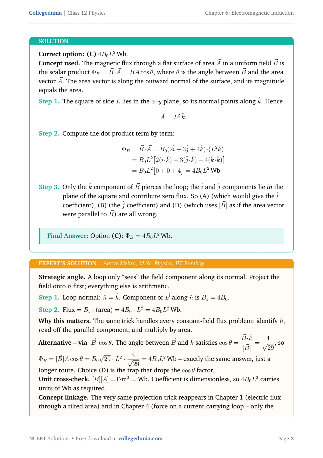
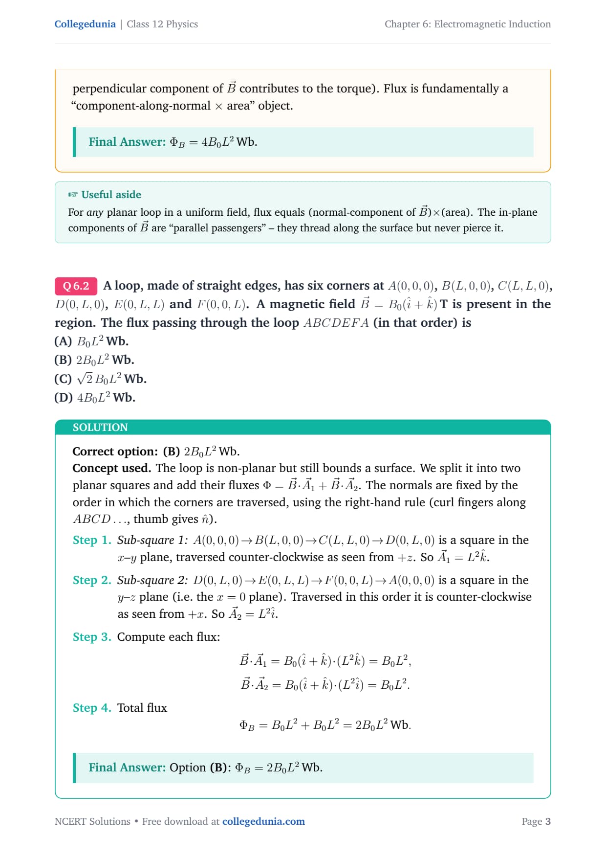
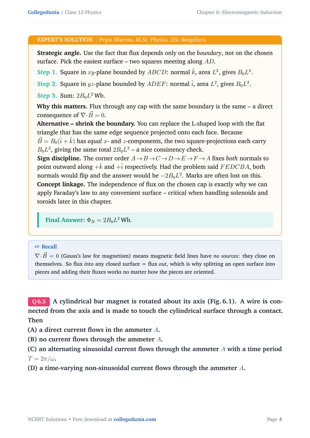
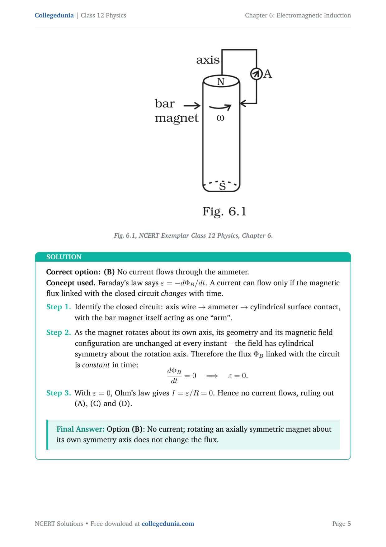
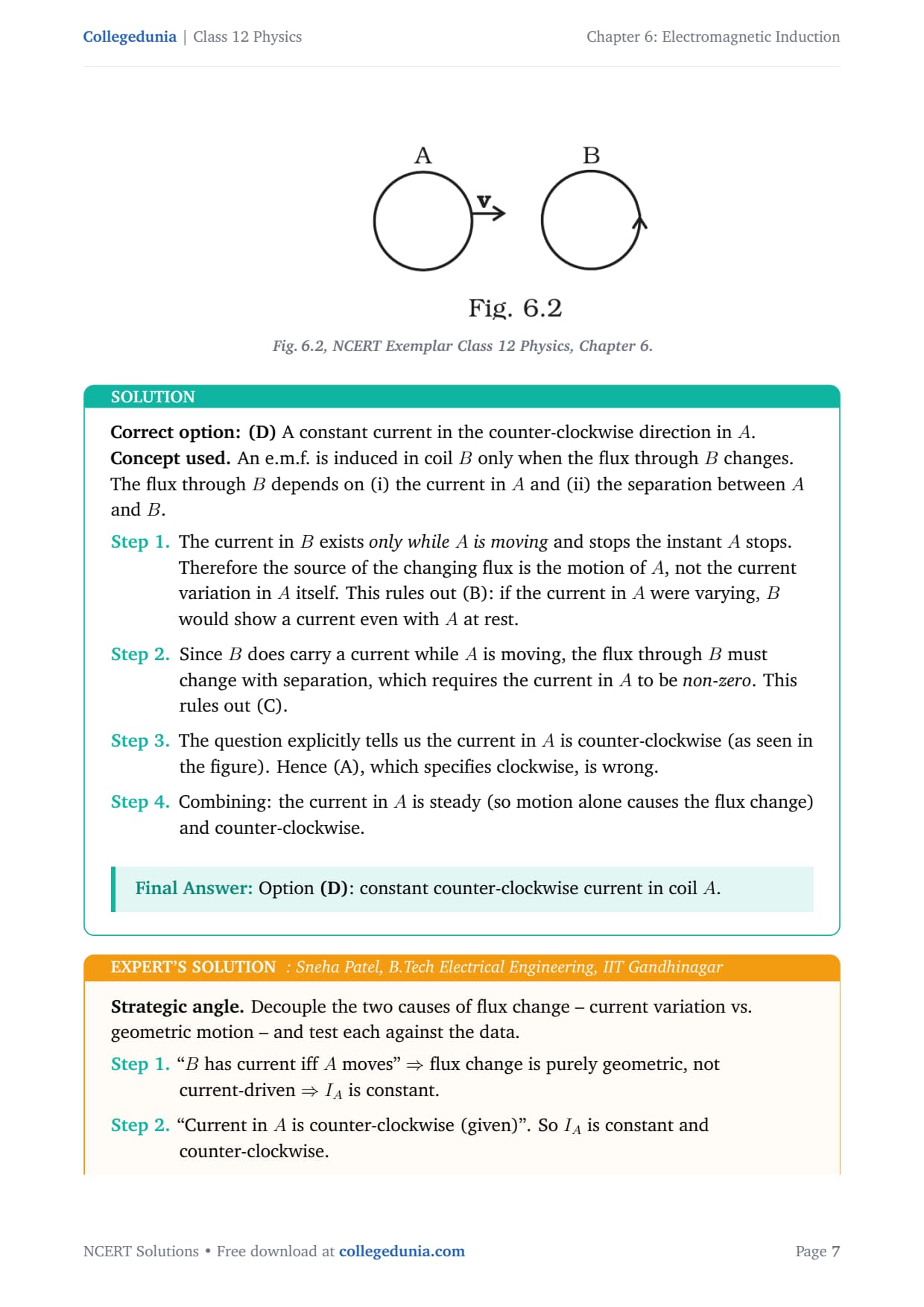
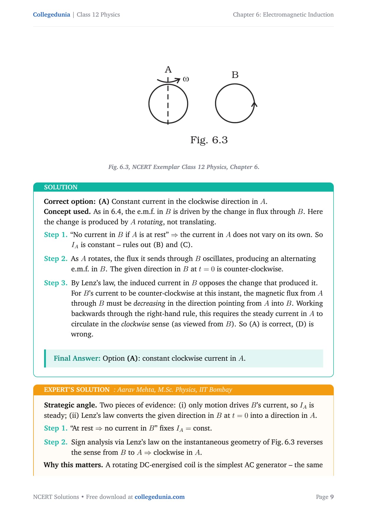

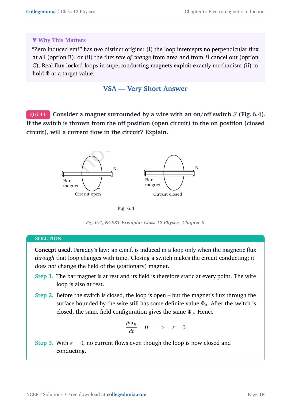
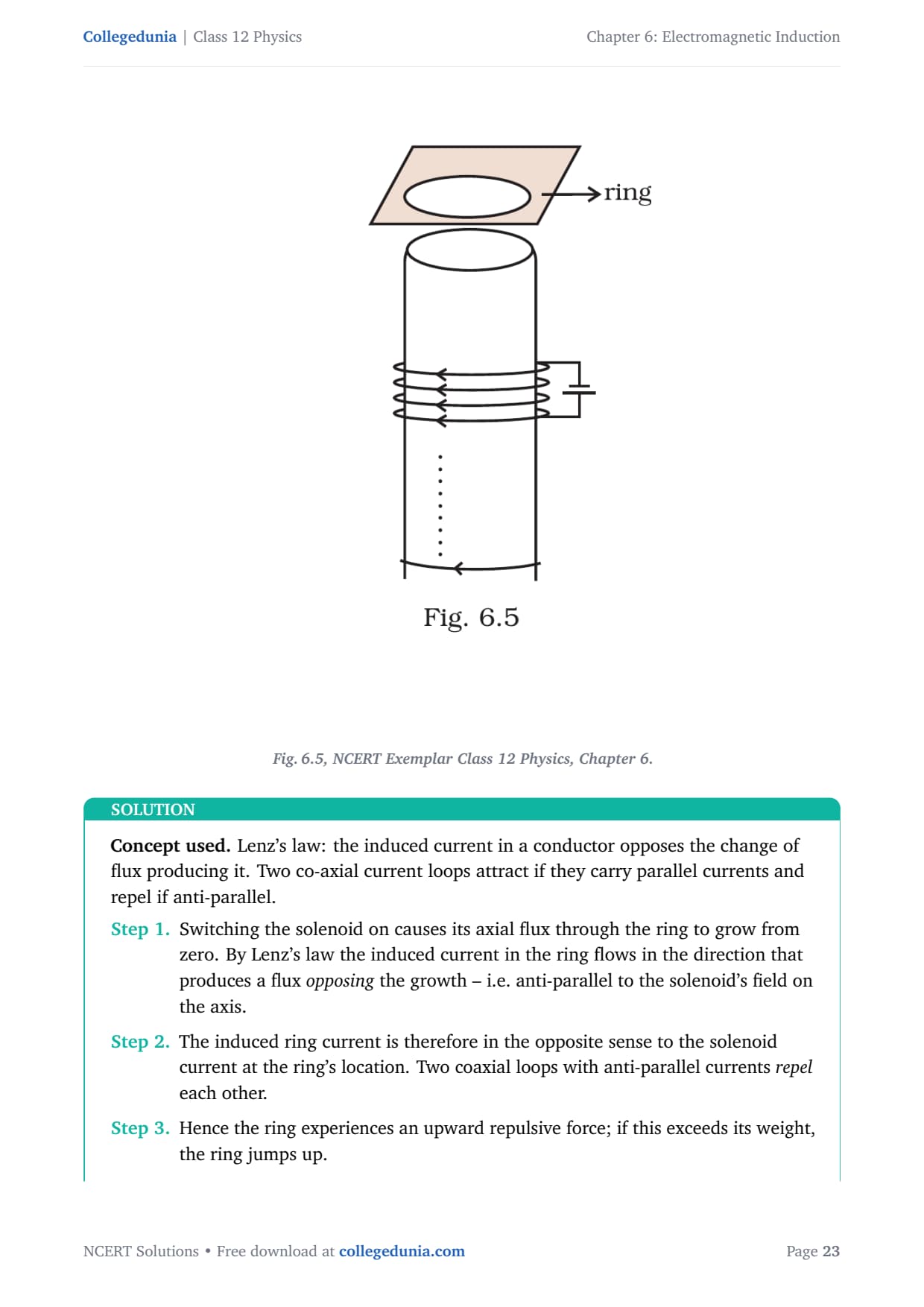
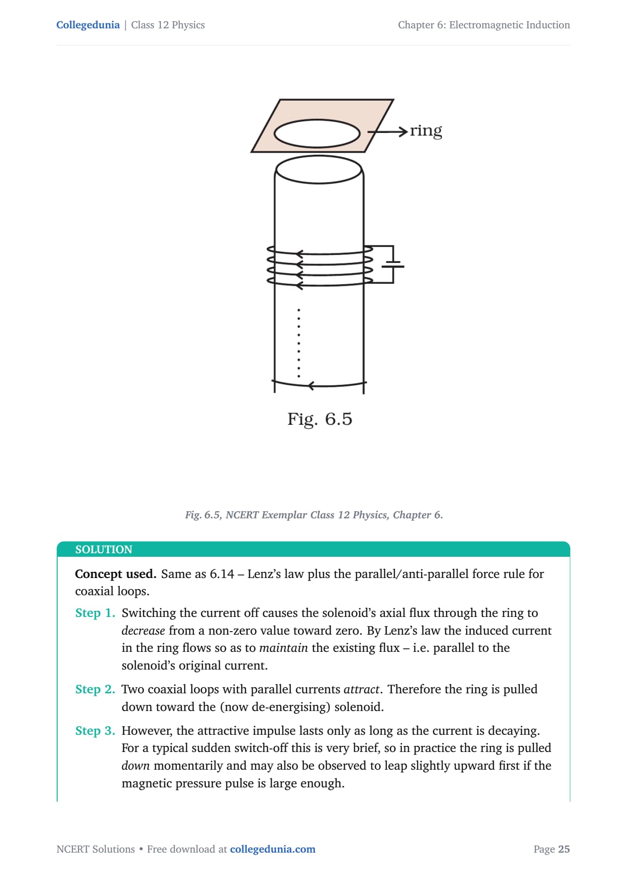
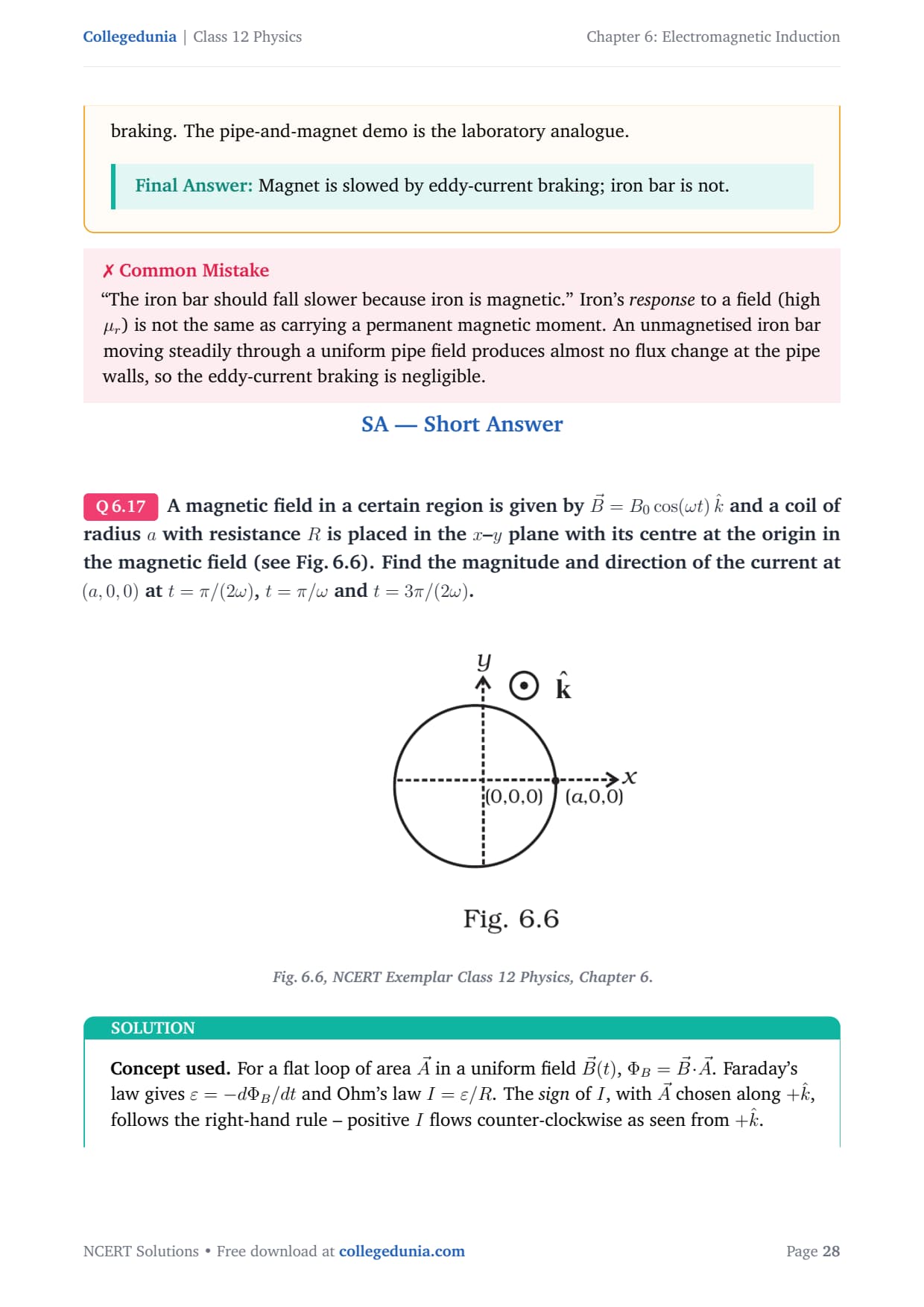
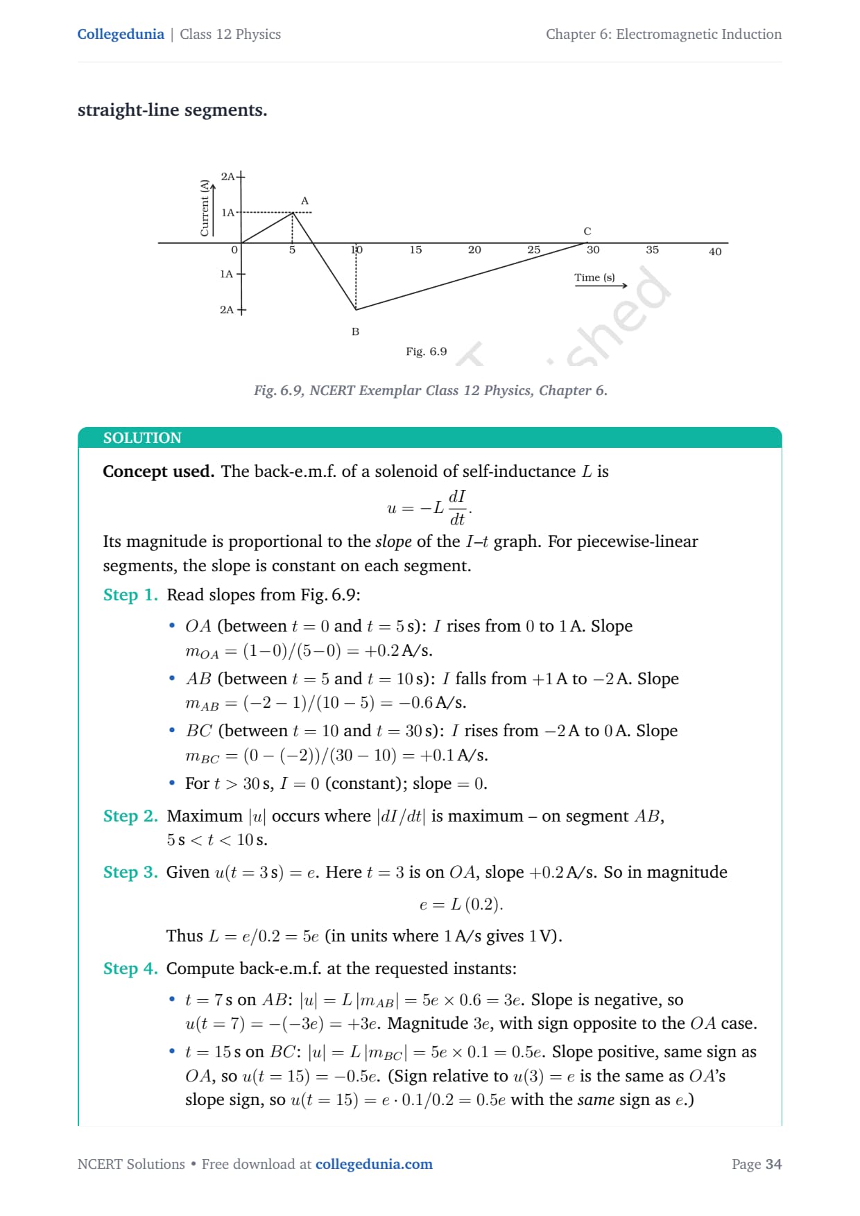
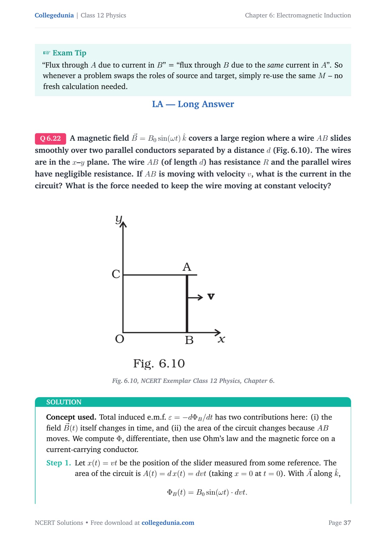
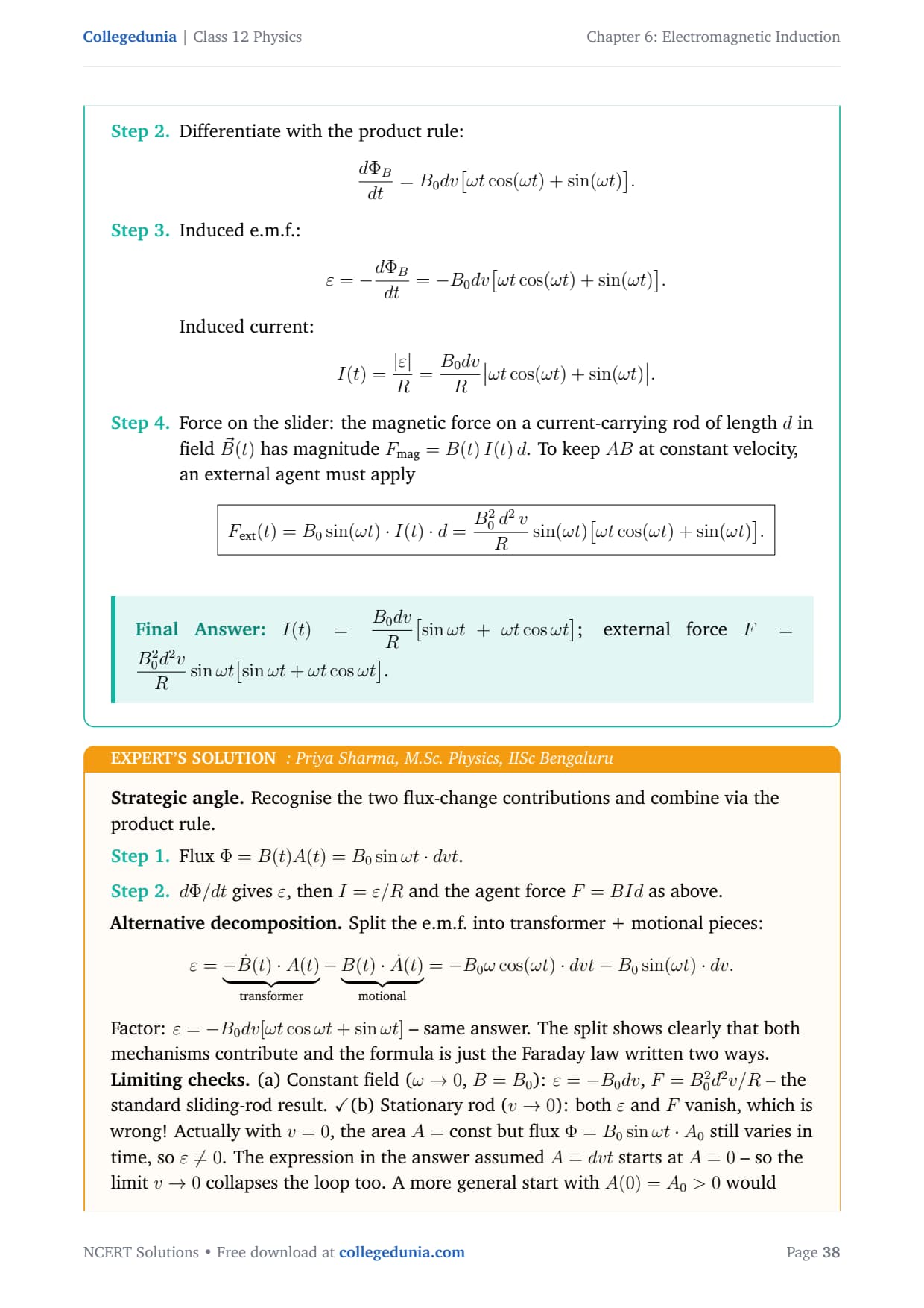
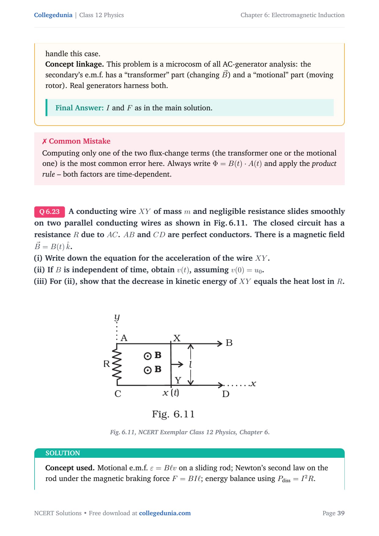
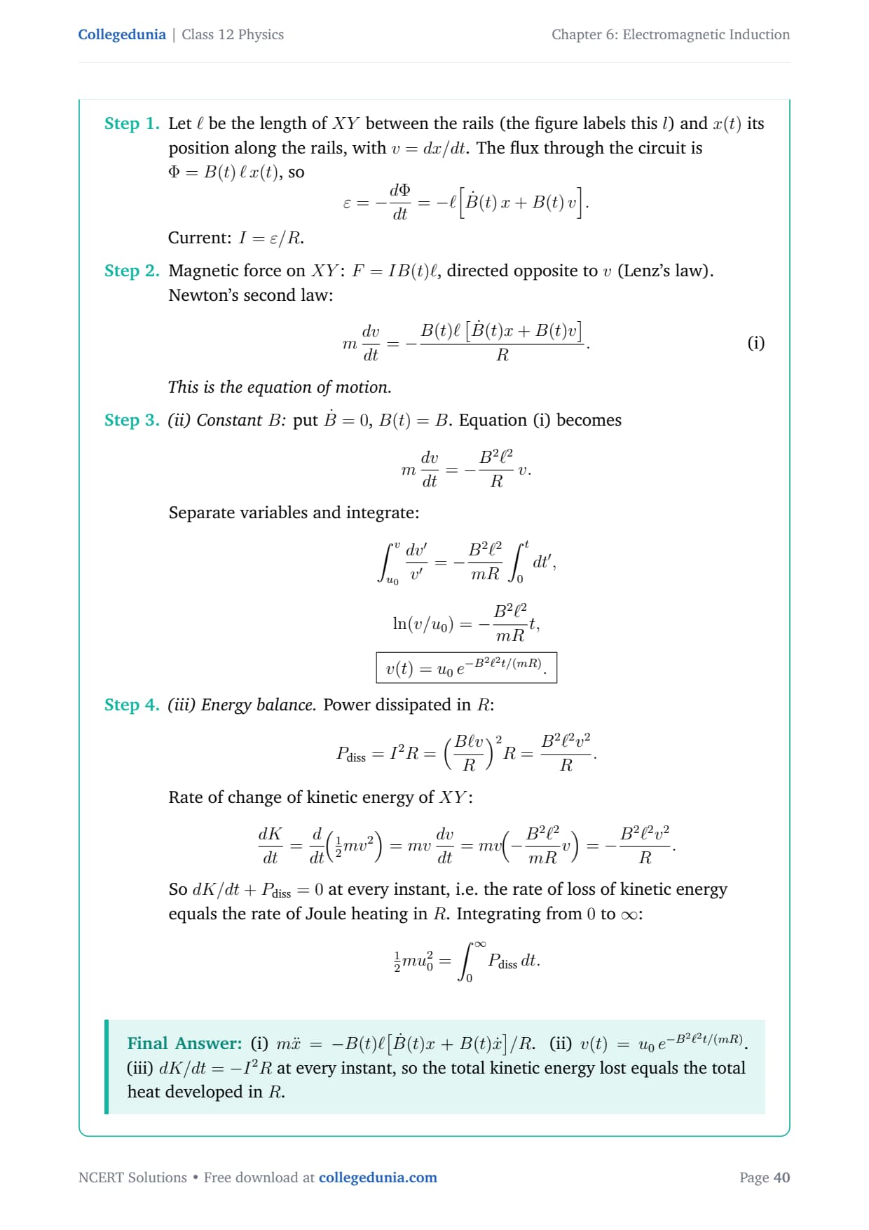
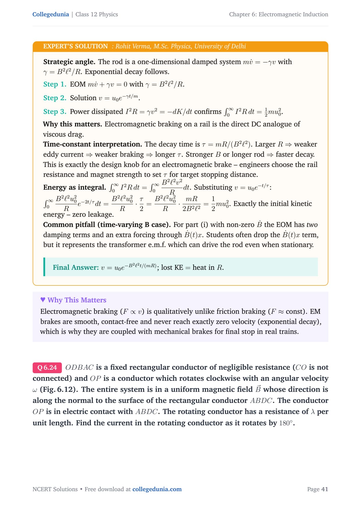
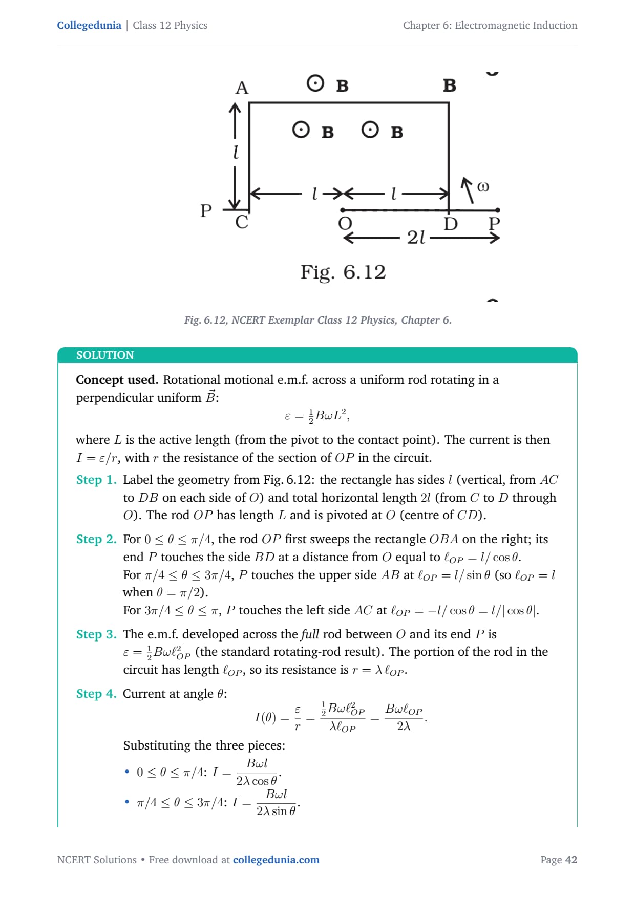
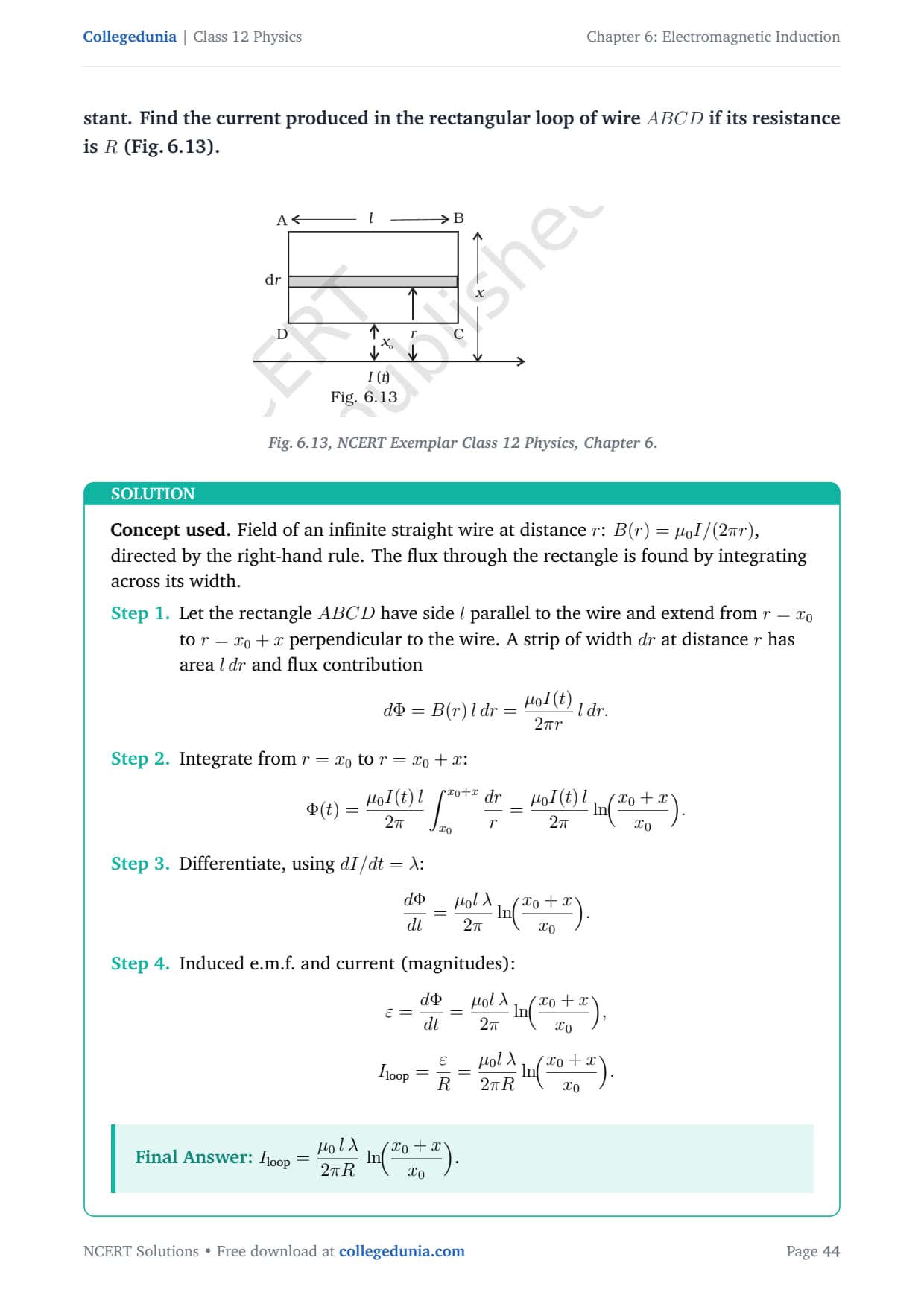
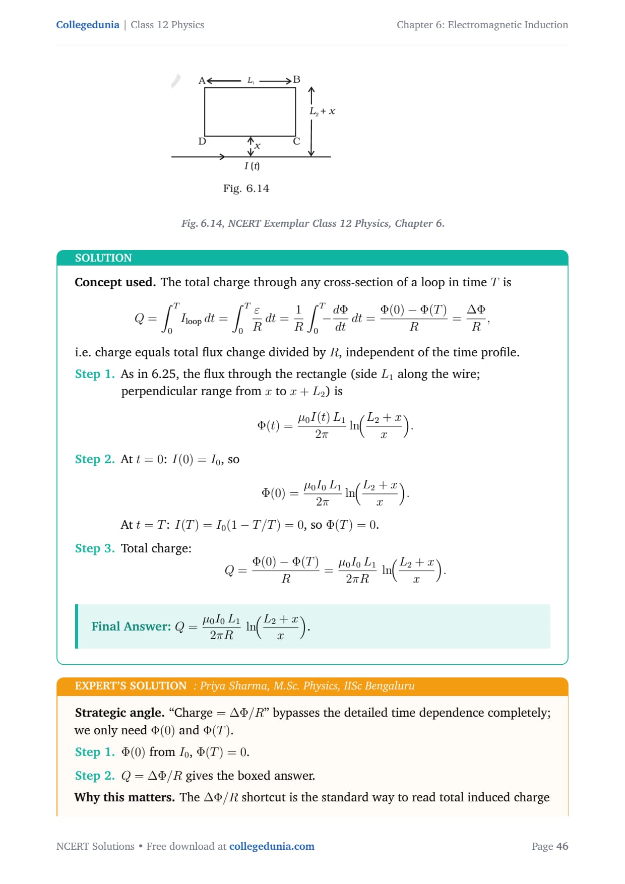
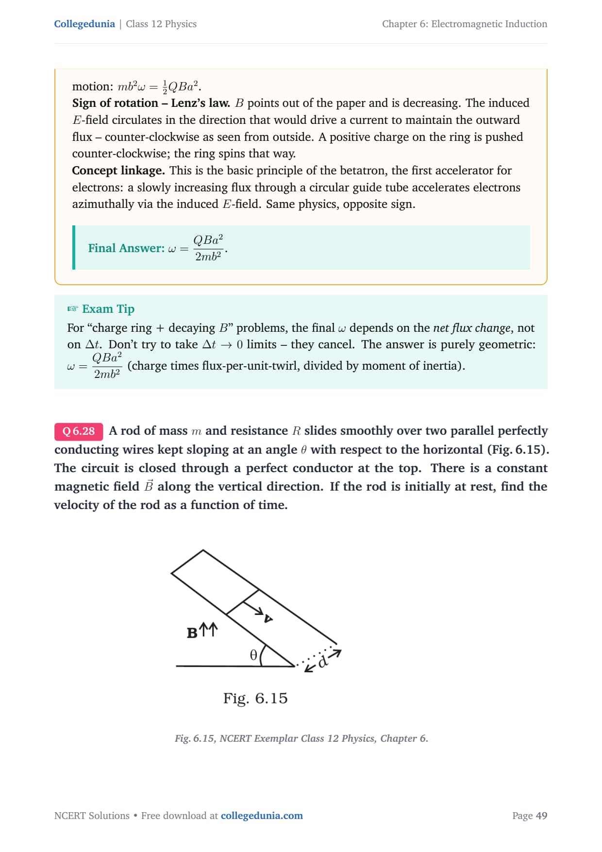
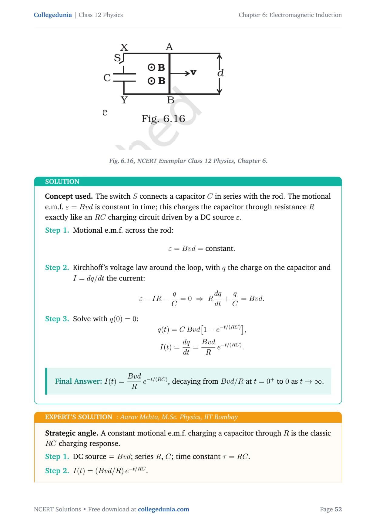
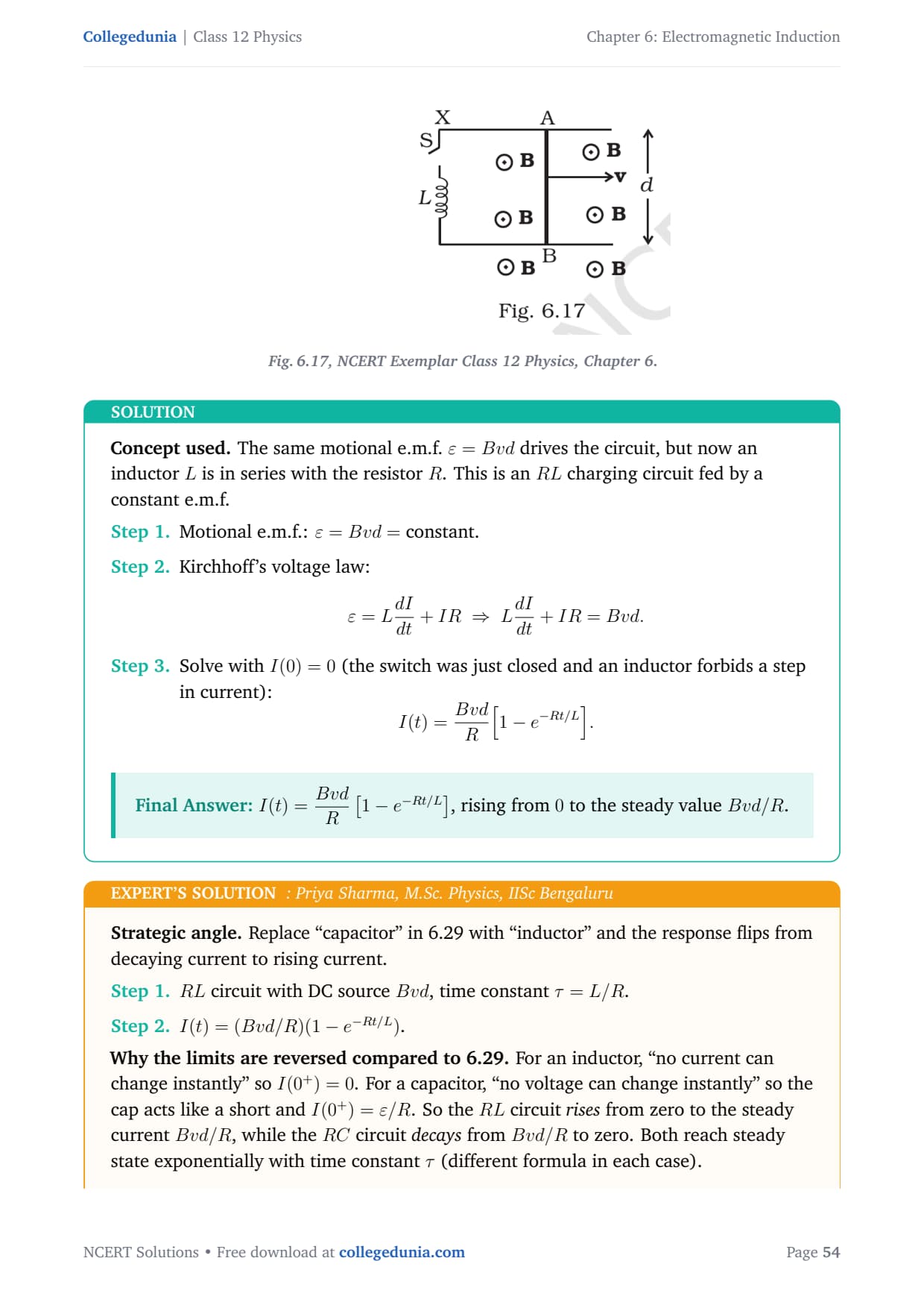
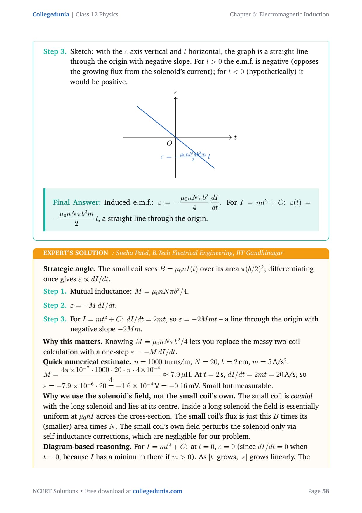
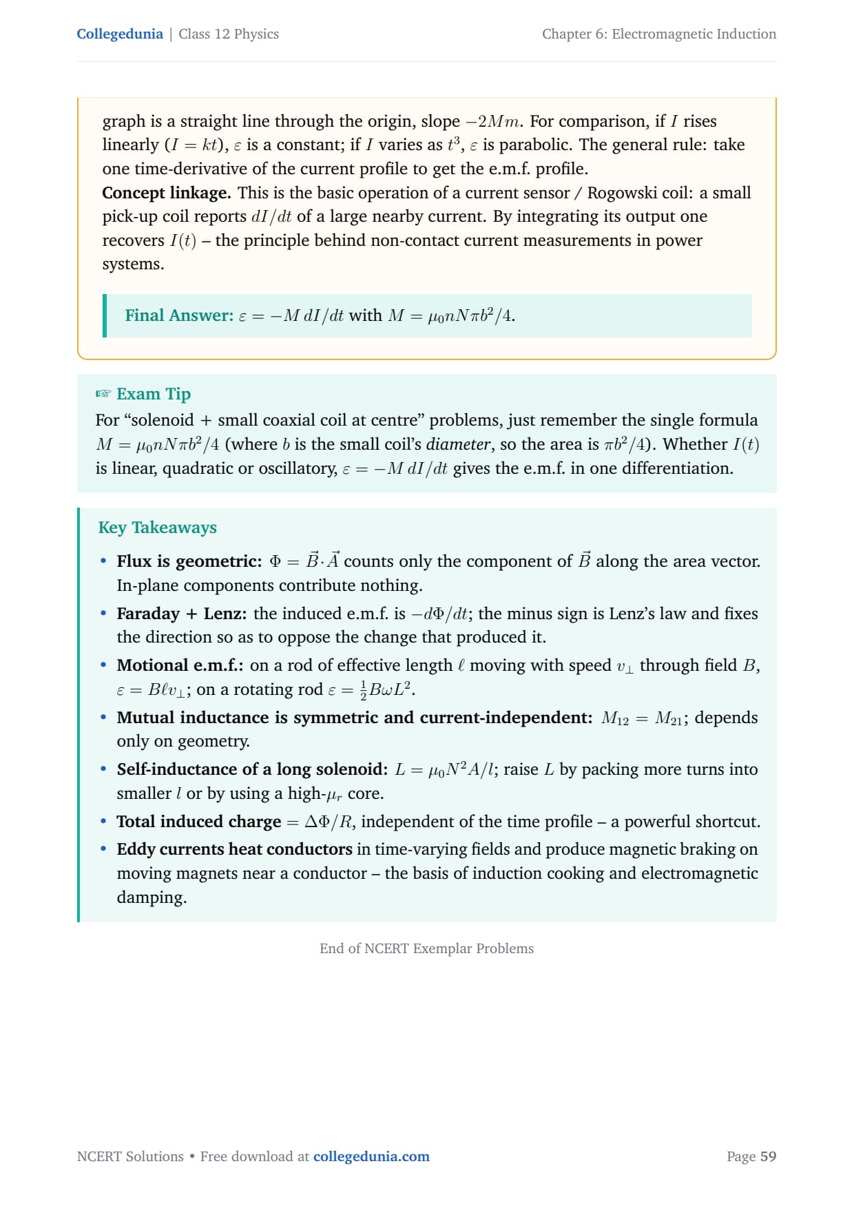


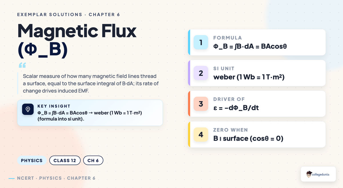
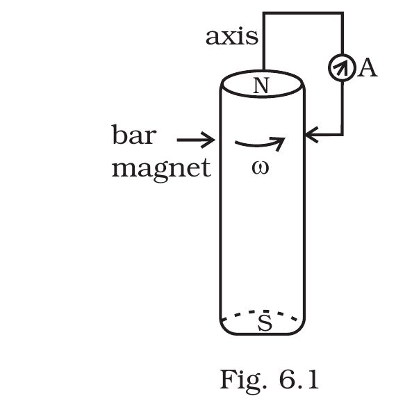
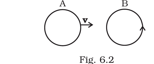
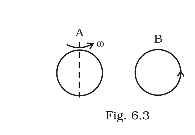
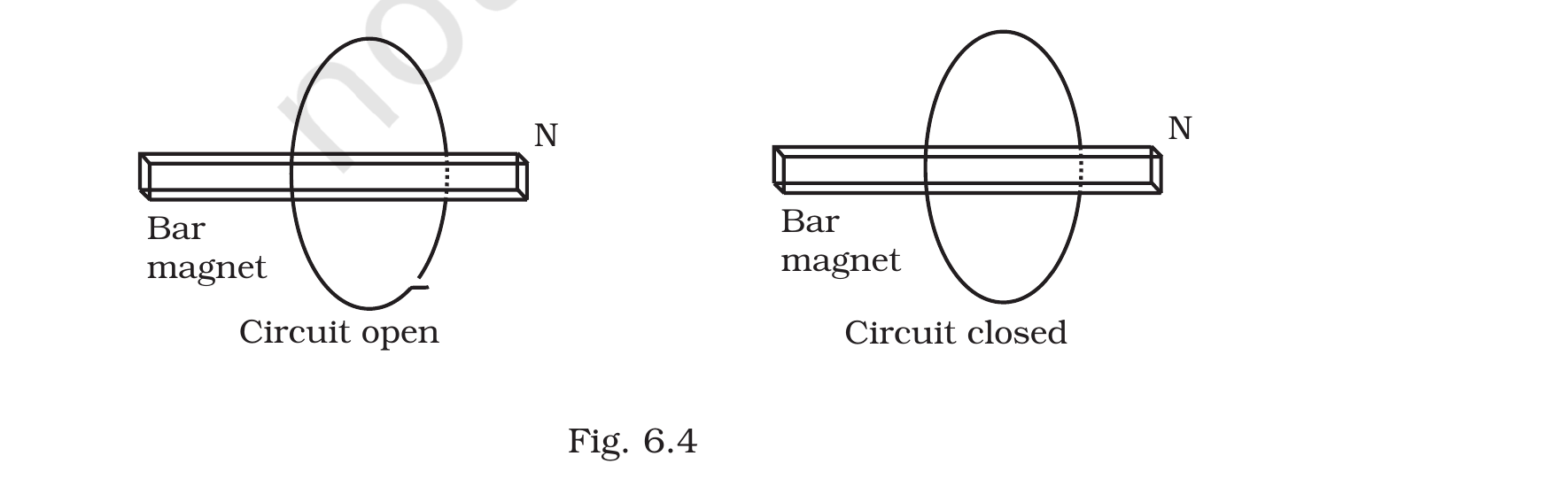
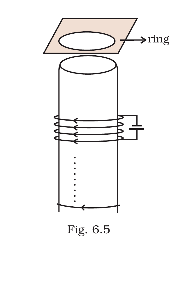
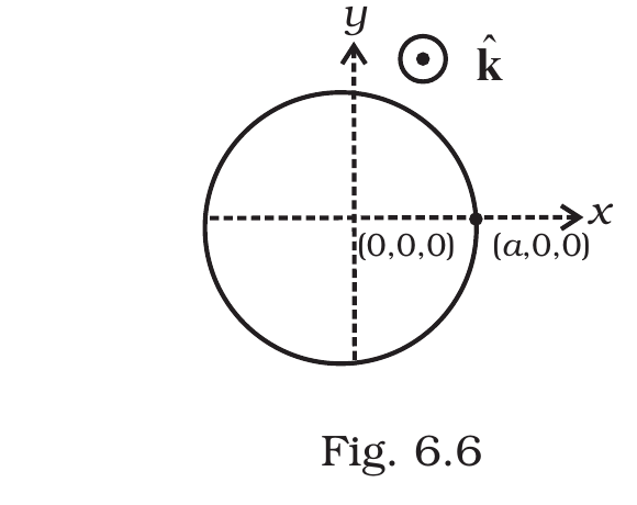
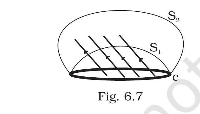
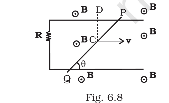
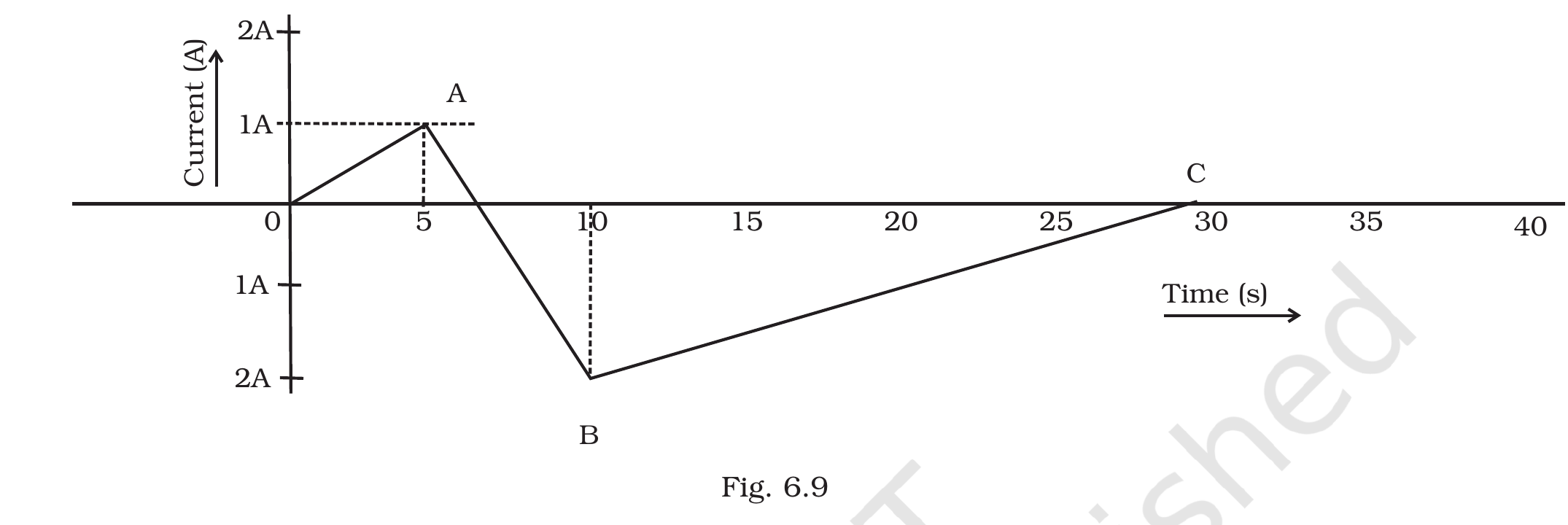
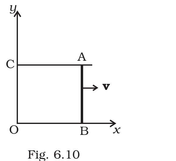
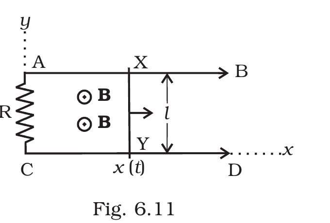
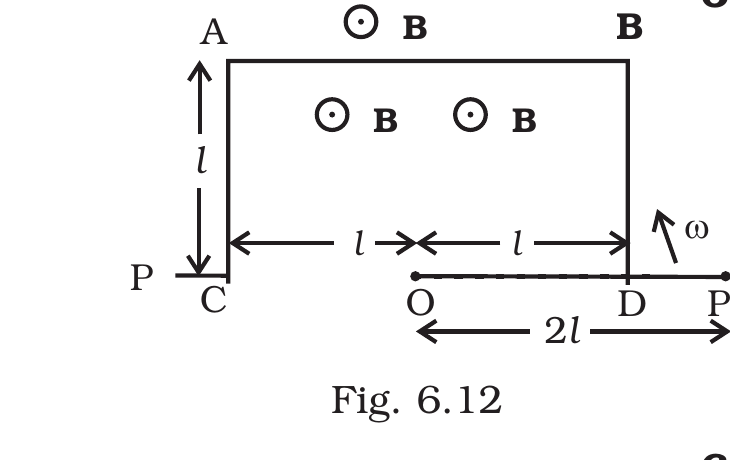
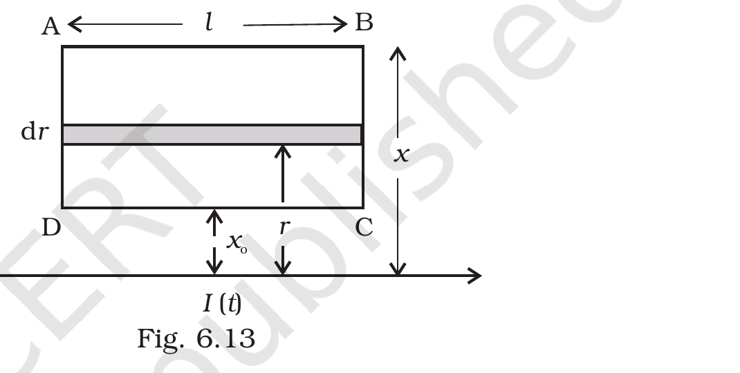
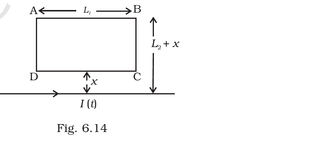
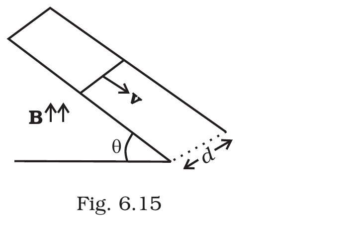
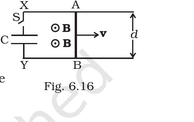
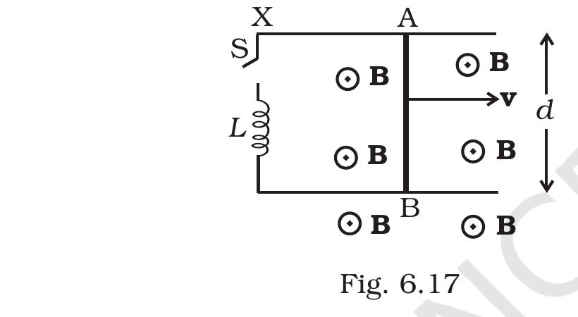



Comments