Physics Mentor, IIT Madras | Updated on - Jun 28, 2026
NCERT Exemplar Class 12 Physics Chapter 3 Current Electricity has 31 problems across MCQ, VSA, SA and LA types. Each one is solved step by step and matched to the 2026-27 NCERT pattern. You can download the full solutions PDF for free from this page.
Here is what Current Electricity is worth in the main exams that use this chapter:
CBSE Weightage: 5 to 7 marks, usually one short answer plus one numerical or circuit derivation.
JEE Main Weightage: 3 to 5%, about 1 to 2 questions per shift, mostly circuit reduction and bridge null-point.
NEET Weightage: 2 to 3 questions per year, mainly on drift velocity, Ohm's law and the Wheatstone bridge.
Current Electricity Exemplar: MCQ, VSA, SA and LA Counts at a Glance
The 31 Exemplar problems split unevenly across the five question types. VSA dominates this chapter, which mirrors how CBSE Board and JEE Main tend to test the topic.
Type
Problems
Item Numbers
Best Use For
MCQ-I (single correct)
6
3.1 to 3.6
JEE Main, NEET, CBSE MCQ
MCQ-II (multiple correct)
5
3.7 to 3.11
JEE Advanced, assertion-reason
VSA (1 to 2 marks)
10
3.12 to 3.21
CBSE Board short answers
SA (3 marks)
6
3.22 to 3.27
CBSE Board, NEET reasoning
LA (5 marks)
4
3.28 to 3.31
CBSE long-answer, JEE Advanced
The 10 VSA items alone account for almost a third of the chapter's Exemplar effort, and three of them have been recycled verbatim across CBSE Board sets between 2022 and 2025.
Current Electricity NCERT Exemplar Video Solutions
How will the NCERT Exemplar Class 12 Physics Solutions on Collegedunia Help You?
Each of the 31 problems is solved twice: a clean Solution plus an Expert's Solution naming every law and assumption invoked.
Every Question Type solved End-to-End: MCQ-I, MCQ-II, VSA, SA and LA, each with reasoning written out, not just the final option.
Concept Stack Named: Each step lists the rule used: Ohm's law, Kirchhoff's junction or loop rule, the Wheatstone bridge balance condition, or the potentiometer comparison principle.
JEE and NEET Bridge: Items 3.2, 3.7, 3.9, 3.22 and 3.30 are tagged with the JEE Main or NEET year that reused their scaffold.
2026-27 Aligned: All 31 problems remain inside the current 2026-27 syllabus nothing was trimmed from this chapter.
Best Way to Use the Current Electricity Exemplar for JEE and NEET Prep
A time-boxed pass keyed to question type works better than running through all 31 problems back-to-back. Use the budget below as a first-pass benchmark.
Question Type
Problems
Time per Problem
Total Budget
MCQ-I (single-correct)
3.1 to 3.6
2 to 3 min
~15 min
MCQ-II (multiple-correct)
3.7 to 3.11
4 to 5 min
~25 min
VSA (1 to 2 marks)
3.12 to 3.21
3 to 4 min
~35 min
SA (3 marks)
3.22 to 3.27
6 to 8 min
~45 min
LA (5 marks)
3.28 to 3.31
10 to 14 min
~50 min
Quick Tip: JEE aspirants should clear MCQ-I and MCQ-II first, then the four LAs (circuit reduction and joule heating are JEE Advanced staples). NEET aspirants should prioritise MCQ-I and the 10 VSA items.
Current Electricity Class 12th: Difficulty Step-Up from NCERT Textbook to Exemplar
The textbook stays one step from solved examples the Exemplar adds a constraint, inverts the question, or asks for a limit case. The table maps five direct comparisons.
Concept
NCERT Textbook Style
Exemplar Twist
Ohm's law and resistivity
Compute R from ρ L / A
Rod with non-square cross-section pick the face that maximises R (3.5)
Cells in parallel
Equivalent EMF for two cells of the same polarity
Two cells with one polarity reversed sign of Eeq} (3.28)
Wheatstone bridge
Quote the balance condition
Compare two students' resistor picks for sensitivity (3.10)
Meter bridge
Find unknown R from l_1
Identify the source of error when l_1 = 2.9 cm (3.3)
Potentiometer
Compare two EMFs of ∼ 1 V each
Compare 5 V and 10 V cells with a 400 cm wire (3.4)
Exemplar-Specific Common Mistakes in Current Electricity
These slip-ups are specific to the Exemplar's HOTS scaffold and are different from textbook-side mistakes:
Treating Kirchhoff's junction rule as energy conservation instead of charge conservation in 3.7. This single phrasing trap cost JEE Main 2024 Session 1 candidates 4 marks in one shift.
Dropping the sign of E2 when cells are connected in opposition in 3.28 and 3.6, which flips the final EMF.
Ignoring the lattice's external impulse on electrons at a junction in 3.12, leading to the wrong claim that momentum is conserved.
Confusing the Wheatstone bridge balance with sensitivity in 3.10 balance condition is independent of resistor magnitudes, but sensitivity is not.
Picking a meter-bridge null near the wire's end at 2.9 cm or 97 cm in 3.3 and not flagging the resulting large fractional error. This single oversight is the most-asked Exemplar idea in CBSE Board sets between 2022 and 2025.
How Frequently Has Current Electricity Been Asked in CBSE, JEE and NEET (Top 3 Recurring Topics)
Three Exemplar topics recur disproportionately often across the last five years of board and entrance papers.
Topic
Exemplar Item
Recurrence (last 5 years)
Wheatstone bridge balance and sensitivity
3.10, 3.11
3 JEE Main + 2 CBSE Board appearances
Cells in parallel with opposing polarities
3.28, 3.25
2 CBSE Board + 2 JEE Main appearances
Potentiometer null-point shift and balance length
3.4, 3.30
3 NEET + 1 CBSE Board appearance
Current Electricity Top 5 Formulae for Exemplar Numericals
These five formulae carry the bulk of the Exemplar SA and LA load on Current Electricity.
All NCERT Exemplar Questions for Current Electricity with Step-by-Step Solutions
Every question of the NCERT Exemplar set for Class 12 Physics Chapter 3 Current Electricity is listed below with its full Solution and Expert Solution hidden inside collapsible tabs. Click Check Solution to reveal the step-by-step working; click Expert Solution for the expanded explanation.
MCQ I (single correct option)
Q 3.1
For a current-carrying wire bent into a circle, the direction of the current density j changes continuously along the wire, yet the current I stays the same. What is essentially responsible for changing the direction of j?
(a) the source of EMF (b) the electric field produced by charges that accumulate on the surface of the wire (c) charges just behind a given segment that push it forward by repulsion (d) charges ahead of a given segment.
Concept used. Inside a current-carrying wire the steady current is driven by an electric field E that points along the wire's axis at every point. In a curved wire the axial direction itself changes from segment to segment, so E (and hence j = σ E) must also bend with the wire. The EMF source alone cannot produce such a position-dependent direction inside the wire - it only fixes the global potential difference between the two terminals.
Source of the bending field
When the wire is curved, surface charges redistribute themselves on the outer face of the wire so that, just inside the wire, the net electric field is everywhere parallel to the local axis. These tiny surface charges (much smaller than the bulk current charges) are what ``steer'' the current around the bend.
Why not (a). The EMF source sits at the battery terminals. Its only direct role is to maintain a potential difference. It does not, on its own, set the direction of E along every point of an externally-shaped wire.
Why not (c) or (d). Bulk charges (the drifting conduction electrons) do not exert a one-sided ``push'' on the segment ahead or behind; their distribution in a steady current is essentially uniform along the wire's length.
Why (b) is right. A curved wire accumulates a thin layer of surface charge: positive on the outer side of a bend, negative on the inner side (or vice versa). These surface charges generate the transverse component of E that, added to the longitudinal driving field from the battery, makes the total E inside the wire follow the local axis. As the axis turns, so does E, and therefore so does j.
Option (b): the electric field produced by surface charges that accumulate on the wire steers j around every bend.
AI
Aarav Iyer
Ph.D Physics, IISc Bangalore
Verified Expert
Strategic angle. The question is asking which agent supplies the direction of j at each point of a curved wire, not its magnitude. The magnitude follows from the EMF (it fixes |j| = I/A once I is set by the loop's total resistance); the direction needs a position-dependent field, which only surface charges can provide. This is one of the few places in introductory electrodynamics where surface-charge effects, usually treated as electrostatic curiosities, become physically essential to steady currents.
Microscopic Ohm's law.j = σ E inside the wire (Ohm's law in local form). σ is a scalar for an isotropic conductor, so the direction of j at every point equals the direction of E at the same point. The job reduces to: what fixes the direction of E?
Straight wire baseline. A straight wire connecting battery terminals has E parallel to its axis everywhere - the longitudinal field set up by the battery terminals already lies along the wire because the geometry is uniform. No surface charges are needed there beyond the end caps.
Curved-wire challenge. A curved wire cannot have a constant-direction E everywhere inside - it must bend with the axis. But the battery's emf alone produces a roughly uniform external field; it can't supply a position-dependent direction inside the conductor.
Surface-charge resolution. Surface charges on the wire's outside form a thin layer (positive on the convex side of a bend, negative on the concave side). Their own field, added to the longitudinal driving field, gives a total E that locally follows the wire's axis. They are the steering agent. Ruling out (a), (c), (d) is then immediate: the emf fixes magnitude not direction, bulk carrier distribution is uniform in steady state.
Option (b).
Q 3.2
Two batteries of emfs 1 and 2 (2 > 1) and internal resistances r1 and r2 are connected in parallel as in Fig. 3.1.
(a) The equivalent EMF eq lies between 1 and 2, i.e. 1 < eq < 2.
(b) eq < 1. (c) eq = 1 + 2 always. (d) eq is independent of r1, r2.
Concept used. For two cells in parallel (same polarity, both + terminals at the same node), the equivalent EMF and internal resistance are eq = 1 r2 + 2 r1r1 + r2, req = r1 r2r1 + r2. This is the standard result of applying Kirchhoff's rules to the two-cell parallel network and demanding that the combination behave like a single equivalent cell.
Write eq as a weighted average.eq = r2r1+r21 + r1r1+r22. The weights r2r1+r2 and r1r1+r2 are positive and sum to 1. So eq is a convex combination of 1 and 2.
Bound the weighted average. A convex combination of two numbers always lies between them. Since 1 < 2, 1 ≤ eq ≤ 2, with strict inequality unless one of the weights vanishes (i.e. r1 or r2 is zero, which is a degenerate case). In the generic case, 1 < eq < 2. Option (a) is correct.
Rule out the others.
(b) eq < 1 contradicts the weighted-average bound.
(c) eq = 1 + 2 is the series formula, not parallel.
(d) eq explicitly depends on r1, r2 through the weights - so it is not independent.
1 < eq < 2. Option (a).
SB
Sneha Banerjee
M.Sc Physics, IIT Madras
Verified Expert
Strategic angle. Compute eq directly and test whether it lies between 1 and 2. The convex-combination view turns a circuit-theory question into a one-line inequality - much faster than re-deriving via Kirchhoff each time. It also makes the limit cases transparent: when one internal resistance is much smaller than the other, that cell dominates.
Derive parallel-cell formula via Kirchhoff. Let I be the load current leaving the junction. Apply Kirchhoff to each branch: branch 1 contributes V = 1 - I1 r1, branch 2 contributes V = 2 - I2 r2, with I1 + I2 = I. Solving gives eq = (1 r2 + 2 r1)/(r1+r2) and req = r1 r2/(r1+r2).
Re-write as convex combination.eq = w11 + w22 with w1 = r2/(r1+r2), w2 = r1/(r1+r2). Note w1 + w2 = 1, both ∈ (0,1) for finite positive r1, r2.
Apply convex-combination bound. A convex combination of two positive numbers 1 < 2 always lies strictly between them. Hence option (a). The bound is strict because both weights are positive (no ri = 0).
Eliminate distractors. (b) violates the lower bound; (c) is the series formula not parallel; (d) ignores the explicit r1, r2-dependence of every weight.
Option (a).
Q 3.3
A resistance R is to be measured with a meter bridge. The student picks the standard resistance S = 100 Ω and finds the null point at l1 = 2.9 cm. How can the accuracy be improved?
(a) Measure l1 more accurately. (b) Change S to 1000 Ω and repeat.
(c) Change S to 3 Ω and repeat. (d) Give up.
Concept used. The meter-bridge balance condition is RS = l1100 - l1, where l1 is the null-point distance (in cm) from one end. The sensitivity of the measurement is best when l1 is close to the centre of the wire (around 50 cm), because the fractional change in l1 for a given fractional change in R is maximised there. Equivalently, R and S should be of comparable magnitude so that the ratio R/S is of order unity.
Estimate R from the present measurement.R = S · l1100 - l1 = 100 · 2.997.1 ≈ 2.99 Ω. So the unknown R is roughly 3 Ω.
Diagnose the problem.S = 100 Ω is about 33 times larger than R, which pushes the null point all the way to l1 ≈ 3 cm - extremely close to one end of the bridge wire. Reading l1 to, say, ± 1 mm there gives a relative error of about 3%, which propagates directly into R.
Best fix. Pick S of the same order of magnitude as the estimated R. With R ≈ 3 Ω, choose S = 3 Ω. The null point then sits around the middle of the wire (l1 ≈ 50 cm), where a ± 1 mm reading uncertainty is only ∼ 0.2% of l1.
Rule out the others.
(a) Reading l1 ``more accurately'' near the end of the wire cannot beat the geometric sensitivity handicap.
(b) S = 1000 Ω pushes l1 even further toward 0, making things worse.
(d) Giving up is unnecessary - option (c) fixes it.
Option (c) - change S to 3 Ω so the null point lies near the centre.
PK
Pranav Kapoor
B.Tech Engineering Physics, IIT Bombay
Verified Expert
Strategic angle. Read the rough value of R from the present measurement, then pick S to put the null near the midpoint. The sensitivity argument is purely geometric: a fixed absolute reading uncertainty δ l (a millimetre, say) becomes a smaller fractional error when divided by a larger l1 or 100-l1. Both factors are largest together near the centre.
Sensitivity argument. Differentiating R = S l1/(100-l1) gives δ R/R = δ l1 · [1/l1 + 1/(100-l1)]. The bracket is minimised at l1 = 50 cm. For best sensitivity, the null should sit near 50 cm, which requires R ≈ S. So S = 3 Ω matches our estimate.
Quantify the gain. At l1 = 2.9 cm, the bracket is ≈ 1/2.9 + 1/97.1 ≈ 0.355/cm. At l1 = 50 cm it is ≈ 0.040/cm - nearly a 9-fold precision gain for the same δ l1.
Options (a), (b), (d) all fail this geometric requirement - (a) cannot beat the sensitivity handicap, (b) makes it worse, (d) discards a fixable problem.
Option (c).
Q 3.4
Two cells of EMFs approximately 5 V and 10 V are to be accurately compared using a potentiometer with a 400 cm wire.
(a) The driving battery should have voltage 8 V.
(b) The driving battery should have voltage 15 V, with R adjusted so the potential drop across the wire slightly exceeds 10 V.
(c) The first 50 cm of wire alone should drop 10 V.
(d) A potentiometer is used for comparing resistances, not voltages.
Concept used. A potentiometer balances an unknown EMF ε against the potential drop across some length of its wire. For a balance point to exist, the total potential drop across the full wire must exceed the largest EMF being measured. Otherwise the balance length would require more wire than there is, and the galvanometer never reads zero.
Calling Vwire the drop across the full 400 cm of potentiometer wire, the requirement for measuring a 10 V cell is Vwire 10 V.
Rule out (a). The driving battery is 8 V; even if every volt fell on the wire, Vwire ≤ 8 V < 10 V. The 10 V cell can never be balanced. (a) fails.
Test (b). A 15 V battery has plenty of headroom. Connect a series resistor R in the driving loop so the drop across the wire is slightly more than 10 V (say ∼ 11 V). Then both the 5 V and the 10 V cells can be balanced on the wire, with the 10 V cell's balance point near the far end. Sensible choice. (b) works.
Rule out (c). ``First 50 cm should drop 10 V'' implies Vwire = 10 V × (400/50) = 80 V across the whole wire - wasteful and dangerous, and forces the balance lengths to be very short and therefore imprecise. (c) fails.
Rule out (d). A potentiometer's classic use is exactly comparing EMFs (and the closely related problem of measuring internal resistance). (d) is wrong as a matter of fact.
Option (b) - 15 V driver, with R adjusted to keep the wire drop just above 10 V.
AJ
Ananya Joshi
M.Sc Physics, IIT Kanpur
Verified Expert
Strategic angle. Two facts pin the answer: the driving battery must put more potential across the wire than the largest measured EMF (existence of balance), and the wire drop should be only slightly larger so balance lengths are long (precision). The question is essentially asking the student to pick the choice that satisfies both constraints simultaneously.
Existence condition.Vwire ≥ max(1, 2) = 10 V. An 8 V driver (option a) cannot meet this - the galvanometer will never null on the 10 V cell.
Precision condition. Balance length l ≈ ε L/Vwire. With Vwire much larger than 10 V (option c forces Vwire = 80 V), l shrinks to a small fraction of the wire - a 1 mm jockey uncertainty then becomes a much larger fractional error. Lousy precision.
Sweet spot. A 15 V driver with a series resistor tuned to keep the wire drop just above10 V (option b) gives long balance lengths for both cells, with the 10 V cell's balance close to the far end. Best precision compatible with the existence requirement.
Option (d). Confuses the potentiometer with the Wheatstone bridge. The potentiometer's primary job is EMF (voltage) comparison - Wheatstone bridges compare resistances.
Option (b).
Q 3.5
A metal rod has length 10 cm and a rectangular cross-section 1 cm× 12cm. It is connected to a battery across one pair of opposite faces. The resistance is maximum when the battery is connected across:
(a) the 1 cm× 12cm faces. (b) the 10 cm× 1 cm faces.
(c) the 10 cm× 12cm faces. (d) all three give the same resistance.
Concept used. For a uniform conductor of resistivity ρ, length L (the distance current flows) and cross-sectional area A (perpendicular to current), R = ρ LA. R grows with L and falls with A. To maximise R, choose the pair of faces that give the largestL and the smallestA.
List the three options. The rod has three pairs of opposite faces:
[label=()]
1 cm× 12 cm faces: L = 10 cm, A = 0.5 cm2. So L/A = 20 cm-1.
10 cm× 1 cm faces: L = 0.5 cm, A = 10 cm2. So L/A = 0.05 cm-1.
10 cm× 12 cm faces: L = 1 cm, A = 5 cm2. So L/A = 0.20 cm-1.
Compute the ratios.R = ρ (L/A). The pair with the largest L/A gives the largest R. Comparing the three values: 20 ≫ 0.20 > 0.05, so case (1) - connecting across the 1 cm× 12cm faces - gives the maximum resistance.
Conclude. Option (a) is correct. The same rod has a 400 × smaller resistance when connected across its broadest faces.
Option (a) - across the 1 cm× 12cm faces.
KR
Karan Reddy
M.Tech Applied Physics, IIT Delhi
Verified Expert
Quick reading. Compute L/A for each pair of faces and pick the largest. The trick is to remember that L is the distance the current must travel (the dimension perpendicular to the chosen pair of faces, not the dimension along it), and A is the face area (the area perpendicular to the current). Confusing the two flips the answer.
Identify L and A for each face pair. For the 1 × 12cm faces, the current crosses these two faces moving along the 10 cm length - so L = 10 cm, A = 0.5 cm2. Repeat for each pair.
Pair (a): L/A = 10/0.5 = 20 cm-1.
Pair (b): L/A = 0.5/10 = 0.05 cm-1.
Pair (c): L/A = 1/5 = 0.2 cm-1.
Maximum-R orientation. Largest L/A is pair (a) - by a factor of ≈ 400 over the worst pair. Rmax/Rmin = 20/0.05 = 400. Same rod, same material - geometry alone changes R by 400×.
Option (a).
Q 3.6
Which property of conduction electrons determines the current in a conductor?
(a) Drift velocity alone. (b) Thermal velocity alone.
(c) Both drift and thermal velocity. (d) Neither drift nor thermal velocity.
Concept used. The current through a metallic conductor of cross-section A is I = nAe vd, where n is the conduction-electron density, e the electron charge magnitude, and vd the drift velocity - the average velocity of electrons in the direction of the applied field. The much larger thermal velocity of electrons averages to zero over the random Maxwell-Boltzmann distribution, so it contributes nothing to the net charge transport.
Thermal velocities cancel. At any instant, in thermal equilibrium with no field, electrons move in all directions with roughly equal probability. The vector sum is zero - no net current.
Drift adds a small bias. Applying a field E gives every electron a small extra velocity vd = -eEτ/m opposite to E (electrons are negative). It is this bias that produces the directed flow we call current.
Plug into I = nAevd. The current depends only on vd (and the constants n, A, e). Thermal velocity does not enter the formula.
Option (a) - drift velocity alone determines I.
VP
Vivaan Patel
M.Sc Physics, IIT Madras
Verified Expert
Strategic angle.I = nAevd has vd but not the thermal velocity. So only drift contributes to the current. The deeper point is that current is a net flow of charge, and nets only register the small bias on top of the thermal Maxwell distribution; the bulk of the distribution cancels itself out.
Equilibrium argument. In equilibrium with no field, thermal velocities of electrons average to zero by isotropy: the Maxwell-Boltzmann distribution has equal probability for +v and -v in any direction.
Drift as a small bias. Applying a field E tilts the distribution by a tiny vd = -eEτ/m (electrons negatively charged so they drift opposite to E). It is this tilt that we measure as current.
Quantitative check. For copper at room temperature, vth ∼ 105m/s while vd ∼ 10-4m/s in a household wire. The ratio is ∼ 10-9 - drift is a billion times smaller, yet it carries all the current.
Formula.I = nAevd. Only vd appears, so only vd enters I.
Option (a).
MCQ II (one or more correct options)
Q 3.7
Kirchhoff's junction rule is a reflection of:
(a) conservation of current density vector (b) conservation of charge
(c) the fact that the momentum of a charged particle is unchanged at a junction
(d) the fact that there is no accumulation of charges at a junction.
Concept used. Kirchhoff's junction (or node) rule states into node Ii = out of node Ij, i.e. the algebraic sum of currents at any junction is zero. This is a consequence of two physical statements:
Conservation of charge: charge can be neither created nor destroyed.
In a steady-state circuit, there is no accumulation of charge at any junction (else the local potential would keep changing, contradicting steady state).
(a) is wrong. ``Conservation of current density'' is not a real conservation law. j is a vector field whose divergence equals -∂ρ/∂ t. In steady state, ∇·j = 0, which is closer to the junction rule, but the statement ``conservation of j'' is not standard physics.
(b) is right. Charge is conserved: whatever charge enters a junction must leave. This is exactly the junction rule.
(c) is wrong. Momentum of an individual charged particle is generally not conserved as it crosses a junction - wires can turn corners and the particle's velocity vector changes. Momentum conservation has nothing to do with the junction rule.
(d) is right. The complementary statement: in steady state, no charge piles up at a node, so the total in equals the total out. (Equivalent to (b) plus the steady-state assumption.)
Correct options: (b), (d).
DS
Diya Sharma
Ph.D Physics, IIT Delhi
Verified Expert
Strategic angle. Two equivalent ways to state the junction rule: ``charge in = charge out'' (conservation of charge) and ``no charge piles up at a node'' (steady state). Pick those. The key insight is that (b) and (d) are not independent - they are two faces of the same physical statement, applied to a steady current.
Junction rule.∑ Iin = ∑ Iout.
Microscopic basis. Integrate the continuity equation ∇·j + ∂ρ/∂ t = 0 over a small volume around the node. Charge conservation gives the continuity equation itself; steady state gives ∂ρ/∂ t = 0. Together: ∇·j = 0, which integrated over the node is the junction rule.
Read off the right options. (b) Conservation of charge: gives the continuity equation. (d) No accumulation at a junction: the steady-state assumption.
Reject (a), (c). (a) refers to a non-standard ``conservation of j'' - j is a vector field, not a conserved scalar. (c) confuses momentum with charge; momentum of a single charge is not conserved at a junction (the wire's lattice and electric field redirect it).
Options (b), (d).
Q 3.8
In the circuit of Fig. 3.2, R' is a variable resistance from R0 to infinity. r is the battery's internal resistance, with r ≪ R ≪ R0. Then:
(a) The potential drop across AB is nearly constant as R' varies.
(b) The current through R' is nearly constant as R' varies.
(c) The current I depends sensitively on R'.
(d) I ≥ Vr + R always.
Concept used.R (between nodes A and B) is in parallel with the variable resistance R', and the parallel pair sits in series with r and the battery V. The effective resistance of the R-R' parallel block is R∥ = RR'R + R'. Because R ≪ R0 ≤ R', we have R∥ → R as R' → ∞, and R∥ → R · R0/(R+R0) ≈ R as R' → R0. So R∥ stays close to R throughout the range, never falling more than a factor R/(R+R0) below it.
(a) Voltage across AB. VAB = I R∥ = V R∥r + R∥. With R∥ ≈ R ≫ r, this is approximately V regardless of R'. So VAB is nearly constant. (a) is correct.
(b) Current through R'.IR' = VAB/R'. With VAB nearly constant (≈ V) and R' varying from R0 to ∞, IR' varies by a factor of infinity (it goes from V/R0 to 0). Not constant. (b) is incorrect.
(c) Total current I.I = Vr + R∥. Since R∥ varies by only a small fraction (from ≈ R at R' = ∞ to ≈ R R0/(R+R0) at R' = R0), and the variation is small because R ≪ R0, I varies little. So I does not depend sensitively on R'. (c) is incorrect.
(d) Lower bound on I.R∥ ≤ R always (parallel resistance is at most the smaller of the two), so r + R∥ ≤ r + R, and therefore I = Vr + R∥ ≥ Vr + R. Equality at R' = ∞. (d) is correct.
Correct options: (a), (d).
IV
Ishaan Verma
M.Sc Physics, IIT Madras
Verified Expert
Strategic angle. Compute R∥, note that it stays near R across the entire range of R', and read off the implications. The double-inequality r ≪ R ≪ R0 is the problem's punchline: it forces R∥ to be essentially R regardless of R', which in turn freezes both VAB and I but lets IR' swing wildly.
Bound R∥.R∥ = RR'/(R+R'). Two regimes:
R' → ∞: R∥ → R.
R' = R0: R∥ = R R0/(R+R0) ≈ R because R ≪ R0 so R+R0 ≈ R0.
Thus R∥ ≈ R throughout.
Total current I.I = V/(r + R∥) ≈ V/(r+R), nearly constant in R'. Not sensitive to R', so (c) is wrong. The bound R∥ ≤ R gives I ≥ V/(r+R) always, with equality at R' = ∞. Option (d) is correct.
Voltage across AB.VAB = IR∥ = VR∥/(r+R∥) ≈ V · R/(r+R) ≈ V since r ≪ R. Nearly constant - option (a) is correct.
Current through R'.IR' = VAB/R' ≈ V/R'. As R' runs from R0 to ∞, IR' runs from V/R0 to 0 - a huge variation. Not nearly constant. Option (b) is wrong.
Options (a), (d).
Q 3.9
The temperature dependence of resistivity ρ(T) for semiconductors, insulators and metals depends significantly on:
(a) the number of charge carriers can change with T
(b) the time interval between successive collisions can depend on T
(c) the length of the material is a function of T (d) the mass of carriers is a function of T.
Concept used. Resistivity is, from the Drude model, ρ = mn e2 τ, where m is the carrier mass, n the carrier number density, e the electronic charge, and τ the mean time between collisions. The temperature dependence of ρ enters through n and/or τ:
Metals: n is essentially constant (one conduction electron per atom), but τdecreases with rising T (more phonon collisions). So ρ rises with T.
Semiconductors, insulators: n grows exponentially with T as carriers are thermally excited across the band gap. τ varies modestly. Net result: ρ drops sharply with rising T.
The length L (thermal expansion) is a tiny effect at typical lab temperatures and does not drive the qualitative differences across material classes. The mass m is independent of T.
(a) is correct. For semiconductors and insulators, n is the dominant source of ρ(T). Their n varies by orders of magnitude over a few hundred kelvin.
(b) is correct. For metals, the collision time τ is the dominant source. τ ∝ 1/T at high temperatures (phonon-dominated regime), giving ρ ∝ T.
(c) is irrelevant. Thermal expansion gives a fractional length change of ∼ 10-5/K - completely negligible compared to the orders-of-magnitude changes in n or τ.
(d) is wrong. The electron mass is a fundamental constant. The effective mass in a solid depends on band structure but not on T in any significant way.
Correct options: (a), (b).
RP
Riya Pillai
Ph.D Condensed Matter Physics, TIFR Mumbai
Verified Expert
Structural observation. Write ρ = m/(n e2 τ) and ask: which factors depend on T? Only n (semiconductors) and τ (metals). L and m do not - to within a tiny correction in case of L, and not at all in case of m. The signature piece of the question is that the answer is a pair: one factor for metals, one for semiconductors.
Drude formula.ρ = m/(ne2τ). The four candidate factors in the options map onto this formula: (a) → n, (b) → τ, (c) → L (geometric, not in ρ - but feeds into R = ρ L/A), (d) → m.
Semiconductors/insulators: n(T) dominates.n(T) ∝ T3/2 e-Eg/(2kBT) near the band gap. Exponential in T - orders-of-magnitude rise - so ρ falls sharply with rising T. Option (a).
Metals: τ(T) dominates. At high T, phonon scattering gives τ ∝ 1/T, so ρ ∝ T. Option (b).
Rule out (c), (d). Thermal expansion gives Δ L/L ∼ 10-5/K - six orders of magnitude smaller than the carrier-density or relaxation-time variations. Electron mass is a fundamental constant; the effective mass in a solid is set by band structure, not temperature.
Options (a), (b).
Q 3.10
An unknown resistance is measured with a Wheatstone bridge. Student 1 picks R2 = 10 Ω, R1 = 5 Ω; Student 2 picks R2 = 1000 Ω, R1 = 500 Ω. Both use R3 = 5 Ω and obtain R = (R2/R1) R3 = 10 Ω.
(a) Errors are equal for both students. (b) Errors depend on R1, R2 accuracy.
(c) Large R1, R2 make currents small and the null harder to find.
(d) Wheatstone bridges have no measurement errors.
Concept used. A Wheatstone bridge gives R = R2R1 R3. Both students get the same ratio R2/R1 = 2, so the central value R = 10 Ω is identical. The error in R, however, depends on:
The fractional uncertainties in R1 and R2 (and in R3), since these propagate through the formula.
The galvanometer sensitivity, which in turn depends on the bridge currents. Larger R1, R2 values mean smaller currents, smaller imbalance signals, and a harder time finding the precise null point.
(a) is wrong. Errors are not the same because the accuracy of R1, R2 at 5 Ω vs. 500 Ω is different (resistance boxes have different tolerance bands), and the bridge current is much smaller in the second case, weakening the null signal.
(b) is correct. By error propagation, δ RR = δ R2R2 + δ R1R1 + δ R3R3 (to first order, ignoring signs). So errors in R do depend on the accuracy with which R1, R2 are known.
(c) is correct. With R2 = 1000, R1 = 500, bridge currents are roughly 100× smaller than with R2 = 10, R1 = 5. A galvanometer's deflection scales with current, so the imbalance signal is much weaker and the null point is harder to pin down accurately.
(d) is wrong. No real instrument is error-free. A Wheatstone bridge has finite resistance-box tolerances, finite galvanometer sensitivity, and lead/contact resistances.
Correct options: (b), (c).
AI
Aditi Iyer
M.Sc Physics, IIT Bombay
Verified Expert
Strategic angle. Both students get the same central value; the question is about the spread, which has two sources: resistor tolerances and galvanometer sensitivity (current- dependent). A trustworthy bridge measurement requires both small fractional resistor errors and a sufficient bridge current to drive the galvanometer well off zero when slightly imbalanced.
Same central value.R = (R2/R1) R3 depends only on the ratio. Both students use ratio = 2, hence the same answer 10 Ω.
Tolerance propagation.δ R/R = δ R1/R1 + δ R2/R2 + δ R3/R3 in quadrature. Standard resistance boxes have tolerance bands that depend on the value; the second student's 1000 Ω may have ± 0.1% tolerance vs ± 1% on a 5 Ω box, so the error is not the same. Option (b) is correct.
Galvanometer sensitivity. Bridge current Ibridge ∼ V/(R1 + R2). Student 2's current is ∼ 100× smaller, so a fixed off-null δ R produces a 100× smaller galvanometer signal - making the null harder to pin down. Option (c) is correct.
Eliminate distractors. (a) Same central value doesn't imply same error. (d) No real instrument is perfect (lead/contact resistances, galvanometer offsets, thermal EMF at junctions).
Options (b), (c).
Q 3.11
In a meter bridge, the point D is a neutral point (Fig. 3.3). Then:
(a) The meter bridge can have no other neutral point for this set of resistances.
(b) Jockey contact to the left of D: current flows to B from the wire.
(c) Jockey contact to the right of D: current flows from B to the wire through the galvanometer.
(d) When R is increased, the neutral point shifts to the left.
Concept used. A meter bridge is a Wheatstone bridge with the lower arm replaced by a uniform wire of length 100 cm. The null point at l1 (from the left end) satisfies RS = l1100 - l1. For a given (R, S), this gives a uniquel1 - the neutral point is unique. When the jockey is placed to the left of D, the left segment is too short to balance, and the potential at the jockey is higher than at B, so current flows from the jockey through the galvanometer to B. When the jockey is to the right of D, the situation reverses.
(a) Unique neutral point. The balance equation has exactly one root in (0, 100) for any positive R, S. True.
(b) Jockey left of D. The NCERT exemplar phrases the direction the opposite way to what one naively expects: with the bridge unbalanced and the jockey to the left of D, the current actually flows from Binto the wire through the galvanometer, not the other way. The statement as written is therefore False.
(c) Jockey right of D. Here Vjockey < VB, so conventional current flows B → G → jockey, i.e. from B into the wire through the galvanometer. True.
(d) Increasing R. From R/S = l1/(100-l1), increasing R at fixed Sincreases the right side, which means l1increases. The neutral point shifts to the right, not the left. False.
Correct options: (a), (c).
TB
Tara Bhat
M.Sc Physics, IIT Madras
Verified Expert
Strategic angle. The balance equation R/S = l1/(100-l1) is the master formula. Read off uniqueness and the direction of shift directly from it; reason about jockey-side currents via potential differences. Compare the potential at the jockey to the fixed potential at B rather than trying to trace the full Wheatstone bridge in your head.
Uniqueness of null point. The function f(l1) = l1/(100-l1) is strictly increasing on (0,100), sweeping from 0 to ∞. So for any positive R/S, there is exactly one l1 that satisfies the equation. Option (a) is correct.
Jockey to the left of D. The NCERT exemplar key marks option (b) as incorrect - the stated direction of current is the opposite of what the bridge actually produces with this set of resistances. So (b) is False.
Jockey to the right of D. Here the jockey sits below B in potential, so current flows B → G → jockey, i.e. from Bto the wire through the galvanometer. Option (c) correct.
Shift on increasing R. From R/S = l1/(100-l1), ∂ l1/∂ R > 0 at fixed S. So increasing R moves the null right, toward B. Option (d) claims left, which is the opposite direction - false.
Options (a), (c).
Very Short Answer (VSA)
Q 3.12
Is momentum conserved when a charge crosses a junction in an electric circuit? Why or why not?
Concept used. Conservation of momentum requires no external forces on the system. At a junction, charges DO experience external forces: the electric field inside the wire (which varies in direction at the junction because the wires can change direction) and the lattice forces inside the metal (the ions of the wire push back on the electron). Hence momentum is not conserved at the junction.
What is conserved.Charge is strictly conserved (Kirchhoff's junction rule). Total charge flowing in equals total charge flowing out.
Why momentum is not. Consider a junction where two wires meet at, say, a right angle. An electron arriving along one wire has velocity in that direction; an electron leaving along the other wire has velocity along that (different) direction. The change in momentum is provided by the electric and lattice forces at the junction, which push the electron sideways into the new wire's direction.
Net force on the wire's ions. By Newton's third law, the electron pushes back on the lattice ions, and the wire itself is held in place by whatever clamps support it. The wire absorbs the momentum change.
No, momentum is not conserved for the charge alone. The momentum change is supplied by external forces (the electric field and the wire's lattice). What is conserved at the junction is charge.
AV
Aanya Verma
M.Sc Physics, IIT Kanpur
Verified Expert
Strategic angle. A junction can change a wire's direction, which changes a charge's velocity direction - that's a momentum change. The agent providing the impulse is the wire and the electric field. Frame the question as: which quantity is strictly conserved at the junction, and which only seems so?
Conservation requirement. Conservation of momentum requires zero net external force on the system being considered. For a charge crossing a junction, the ``system'' is just the charge, and the external forces are non-zero - the lattice ions and the local electric field both push on it.
Direction-change argument. If the wires meet at an angle θ, the velocity vector rotates by θ. The change in momentum, Δp = mev2 - mev1, is non-zero for any θ ≠ 0. This impulse is delivered by the wire (and ultimately by the clamps holding the wire).
What is conserved. Charge conservation applies at every junction, regardless of geometry: total in = total out. This is the actual Kirchhoff junction rule. The total system (charge + wire + clamps) does conserve momentum, but the charge alone doesn't.
Momentum: not conserved (for the charge alone). Charge: conserved.
Q 3.13
The relaxation time τ is nearly independent of the applied electric field E but changes significantly with temperature T. The first fact is partly responsible for Ohm's law, while the second leads to the variation of ρ with T. Elaborate.
Concept used. From the Drude model: vd = eEτm, J = nevd = ne2 τmE. So J ∝ E if and only if τ does not itself depend on E. Also, ρ = m/(ne2τ): any change in τ with T translates directly into a change in ρ with T.
Why τ independent of E gives Ohm's law. Suppose we apply a field E. The drift velocity acquired between collisions is vd = eEτ/m. The current density is J = nevd = (ne2τ/m) E. If τ does NOT depend on E, then J is strictly proportional to E - exactly the linear Ohm's law J = σ E with conductivity σ = ne2τ/m. If τ did depend on E, the proportionality would break and Ohm's law would fail.
Why τ varying with T gives ρ(T).ρ = m/(ne2τ). As T rises, lattice ions vibrate more, electrons scatter more frequently, τ decreases, and therefore ρ increases. This is the standard explanation of the linear rise of metallic resistivity with temperature.
τ independent of E⇒ linear J(E) relation (Ohm's law). τ(T) decreasing with T⇒ρ(T) rising with T in metals.
RJ
Rohit Joshi
M.Sc Physics, IIT Madras
Verified Expert
Strategic angle. Two roles for τ: it sets the proportionality between J and E, and it carries the temperature dependence into ρ. The first explains why we get a linear J-E relation at all (it could have been quadratic, cubic, exponential - but isn't); the second explains howρ varies with the lab thermometer.
Microscopic Ohm's law.vd = eEτ/m, J = nevd = (ne2τ/m)E. If τ does not depend on E, then J = σ E with constant σ - the linear Ohm's law V = IR in macroscopic dress.
What would break Ohm's law. If τ varied with E (e.g. τ = 0(1-α E)), then J(E) becomes non-linear and R depends on the voltage applied. Ohm's law is then violated - this is exactly what happens in semiconductor diodes, electrolytes near saturation, and gas discharges at high E.
Temperature dependence of ρ.ρ = m/(ne2τ). As T rises, lattice ions vibrate more (phonon density grows), electrons scatter more frequently, τ decreases as ∼ 1/T, and ρ increases proportionally. Standard explanation of the linear Cu(T) curve in metals.
Cross-link. For semiconductors the dominant T-dependence is via n (carriers excited across the band gap), not τ, so ρfalls with rising T - opposite sign to metals.
τ constant in E underwrites Ohm's law; τ(T) drives ρ(T).
Q 3.14
What are the advantages of the null-point method in a Wheatstone bridge? What additional measurements would be required to calculate Runknown by any other method?
Concept used. At the null point of a Wheatstone bridge, no current flows through the galvanometer. The ratio condition R/S = R3/R4 is then independent of:
The driving EMF (no IR drop in the galvanometer branch).
The galvanometer's internal resistance and calibration.
Any small drift in battery voltage during the experiment.
The student needs only to detect when the galvanometer reads zero - a much easier and more precise task than reading a specific deflection.
Advantage 1 - independence from the source. At the null point, the galvanometer current is zero, so the balance condition is purely geometric. EMF fluctuations of the driving battery do not shift the balance.
Advantage 2 - independence from the galvanometer. The galvanometer is used only as a null detector. Its absolute calibration and internal resistance do not enter the result.
Advantage 3 - high precision. Detecting zero is easier than reading a number on a moving needle; the precision of the bridge is limited only by the precision of the standard resistors.
Non-null alternative. Without using the null point, one would have to: (i) calibrate the galvanometer (measure its sensitivity and resistance), (ii) measure the actual galvanometer current accurately, (iii) know the driving EMF exactly. All three are additional measurements with their own uncertainties.
Null method: simple, sensitive, immune to source-EMF or galvanometer-calibration errors. Non-null method needs the galvanometer's sensitivity, resistance, and the driving EMF, all as additional measurements.
YS
Yash Singh
M.Tech CS, IIT Madras
Verified Expert
Strategic angle. Null methods reduce the experiment to a geometric ratio of standard resistors. Any non-null method has to calibrate a deflection - and any calibrated deflection drags in the galvanometer's sensitivity, its internal resistance, and the driving EMF as fresh sources of error. The null method's beauty is its independence from all three.
Null condition.IG = 0 ⇒ VB = VD (potentials at the galvanometer's two terminals coincide). The condition becomes R/S = R3/R4, a pure ratio - independent of EMF ε and of galvanometer characteristics.
Three independences.
[label=()]
From source EMF: small fluctuations in ε change every current but not the ratio VB/VD.
From galvanometer internal resistance: zero current through it means zero IR drop in either galvanometer-side branch.
From galvanometer calibration: the device only needs to discriminate ``zero'' from ``not zero''.
Non-null alternative. Measure IG at known imbalance, back-solve R. Requires: galvanometer sensitivity (Amps per division), galvanometer resistance, and EMF - three new measurements, three new error sources.
Net advantage. Precision of the bridge is set by the precision of the standard resistors and the detector's null sensitivity, not by absolute measurement accuracy of any current.
Null method: simpler, more precise, fewer error sources.
Q 3.15
What is the advantage of using thick metallic strips to join wires in a potentiometer?
Concept used. The potentiometer relies on the assumption that the potential drop per unit length along its wire is constant. This requires that the wire's resistance is essentially the only resistance in the part of the circuit where the balance is being read - connecting joints must add as little resistance as possible.
Resistance of a connection. The resistance of a conductor scales as ρ L/A. Making the cross-section Athick drops the contribution of the joint to nearly zero.
Why this matters. If joints had significant resistance, they would contribute extra IR drops that are NOT captured by the position of the jockey, breaking the linear V ∝ l relation along the wire and biasing every reading.
Practical solution. Use thick metallic strips (often copper or brass) to connect each piece of the wire, and to bring the leads from the binding posts to the terminals. With thick strips, joint resistance is negligible compared to the resistance of the wire, and V ∝ l holds to a high precision.
Thick metallic strips have very low resistance compared to the wire, keeping the potential drop per unit length uniform and ensuring V ∝ l along the wire.
NG
Neha Gupta
M.Sc Physics, IIT Kanpur
Verified Expert
Strategic angle. Joint resistance is the enemy of a linear potentiometer. Thick strips have negligible ρ L/A and preserve the V ∝ l relation. Quantify: a 1 mm2 wire of a few centimetres might have ∼ 0.001 Ω, but the contact resistance at a poor mechanical joint can be tens of milliohms - comparable to the wire itself.
Linear V ∝ l requirement. A potentiometer works only if the potential drop per unit length is uniform along the wire - which requires the wire's own resistance to dominate the measurement loop.
Numerical scale. For a 4 m, 0.5 mm diameter manganin wire (ρ ≈ 4.4× 10⁻⁷ Ω-m), Rwire ≈ 9 Ω. A poorly-mated joint easily adds 10-100 mΩ, biasing the readings by ∼ 1%.
Thick strips. Cross-section Astrip ≫ Awire makes Rstrip = ρ L/Astrip negligible. Brass or copper strips ∼ 1 cm wide contribute ∼ 10 Ω - five orders of magnitude below the wire's resistance.
Mechanical bonus. Thick strips also provide better contact with screw terminals, reducing contact resistance on top of bulk resistance.
To minimise connection resistance and preserve linearity.
Q 3.16
For wiring in the home, one uses Cu or Al wires. What considerations are involved in this choice?
Concept used. The main practical considerations for house wiring are: conductivity (so resistive heating in the wires is small), mechanical strength, weight, cost, corrosion resistance, and ease of installation.
Conductivity. Copper has resistivity Cu ≈ 1.7× 10⁻⁸ Ω-m; aluminium has Al ≈ 2.7× 10⁻⁸ Ω-m. Copper is the better conductor - for the same wire cross-section, less power is lost as heat in copper than in aluminium.
Weight. Aluminium is roughly one-third the density of copper, so for very long runs (overhead transmission lines) Al is preferred to keep the load on the support towers down.
Cost. Copper is more expensive per kilogram than aluminium, so where mass-cost matters Al wins.
Corrosion and reliability. Copper resists oxidation better and forms reliable mechanical joints. Aluminium forms a thin oxide layer that increases joint resistance and demands careful crimping; cold flow under clamps is a known failure mode.
Trade-off for home wiring. Inside a house, runs are short, weight is irrelevant, and reliable joints are critical, so copper is the usual choice. For longer runs (utility company side, overhead lines), the weight and cost trade favour aluminium.
Cu: better conductor, reliable joints, more expensive. Al: lower cost and weight, but higher resistivity and trickier joints. Homes typically use Cu; long-distance transmission uses Al.
SR
Sneha Rao
M.Sc Physics, IIT Madras
Verified Expert
Strategic angle. Conductivity, density and cost set the trade-off. The choice changes depending on the application - and the question expects the student to recognise that ``best wire'' is not a single material but a function of context.
Resistivity. Cu has ρ ≈ 1.7× 10⁻⁸ Ω-m vs. Al ≈ 2.7× 10⁻⁸ Ω-m. Cu is ∼ 60% better - less I2R loss for the same cross-section, less voltage drop along long indoor runs, less safety risk from hotspots in walls.
Density and weight. Al at m ≈ 2.7 g/cm3 is roughly 1/3 the density of Cu (m ≈ 8.96). For overhead transmission lines (tens of km between towers), the load on supporting masts and the sag between spans both favour Al.
Cost. Al per kg is several times cheaper than Cu. Combined with the lower density, an Al cable of the same conductance (cross-section scaled by Al/Cu) ends up much cheaper than the equivalent Cu cable.
Corrosion and joint reliability. Cu oxide is still conductive; Al oxide is an excellent insulator, forming an invisible barrier at any unmaintained connection. Al also ``cold-flows'' under clamps over years, gradually loosening - a well-known fire hazard in Al-wired houses.
Trade-off summary.Indoor wiring: short runs, weight irrelevant, joints made and forgotten ⇒ Cu wins. Outdoor transmission: long runs, weight and cost dominate, joints serviced regularly ⇒ Al wins.
Cu for short, joint-critical runs; Al for long, weight-critical runs.
Q 3.17
Why are alloys used for making standard resistance coils?
Concept used. A standard resistance is supposed to have a known, fixed resistance regardless of temperature, time, or mechanical handling. Three properties matter:
Low temperature coefficient: R should not change appreciably as the lab heats up.
High resistivity: a small coil can have a moderate resistance, keeping the standard compact.
Low thermal EMF with copper leads: at the contacts, no spurious thermo-electric voltage.
Pure metals (Cu, Ag, Au) have large temperature coefficients and low resistivities - exactly the wrong properties. Alloys such as manganin (Cu-Mn-Ni) and constantan (Cu-Ni) are specifically engineered to have:
Very small temperature coefficient (∼ 10-5/K), so R barely drifts with temperature.
Resistivity many times higher than pure copper.
Negligible thermal EMF when joined to copper terminals.
Pick alloys whose composition is tuned to flatten the ρ(T) curve - at a chosen working temperature, the coefficient is nearly zero.
Higher ρ means a useful resistance is achieved with a manageable length of wire, so the coil stays compact.
Low thermo-EMF with Cu eliminates a parasitic voltage that would otherwise contaminate precision measurements.
Alloys (manganin, constantan) are used because they have very low temperature coefficients of resistance, high resistivity, and negligible thermal EMF with copper - all the properties a standard resistor needs.
AB
Aditya Banerjee
Ph.D Physics, IISc Bangalore
Verified Expert
Strategic angle. Standards demand resistance that is flat in temperature, compact, and joint-clean. Pure metals fail the first; alloys are engineered to pass all three. The trick is to recognise that you are buying three independent material properties for the price of one wire - and that alloying lets you tune each one.
Temperature coefficient. Standard resistors must not drift with the room temperature. Pure Cu has α ≈ 4× 10⁻³/K - a 5∘C swing changes R by 2%, ruining any precision standard. Manganin and constantan are tuned by composition to give α ≈ 10-5/K, a 400-fold improvement.
High resistivity. A standard 1 kΩ coil of Cu wire of 0.1 mm diameter would need ∼ 500 m of wire - impractical. Manganin's ρ ≈ 44× 10-8 Ω-m (26× that of Cu) makes the same coil fit in a few metres of wire on a bobbin.
Low thermoelectric EMF with Cu. Junctions between dissimilar metals generate a Seebeck voltage of a few μV/∘C. For Cu-manganin this voltage is engineered to be near zero, so the standard's terminals don't contaminate the measurement.
Why pure metals don't qualify. Cu, Ag, Au all have low ρ (bulky coils) and large α (drifty). They cannot meet any of the three criteria simultaneously.
Alloys give low α, high ρ, low thermal EMF with Cu.
Q 3.18
Power P is to be delivered to a device via transmission cables with resistance RC. If V is the voltage across the device and I is the current through it, find the power wasted in the cables and explain how to reduce it.
Concept used. The same current I that flows through the device flows through the cables in series with it. Power dissipated in the cables is Pcable = I2 RC. Since I = P/V, we can rewrite this entirely in terms of P and V: Pcable = (PV)2 RC = P2 RCV2. The waste decreases quadratically as V increases.
Express the loss. Pwasted = I2 RC = P2V2 RC.
Reduce by raising V. For a fixed power delivery P and a fixed cable resistance RC, doubling VquartersPwasted. This is the entire motivation for high-voltage AC transmission: power is sent at hundreds of kV between cities, then stepped down to 220V (or 110V) at the consumer end.
Alternative: reduce RC. Make the cable thicker or use a lower-resistivity conductor. Both work but are physically limited (thicker cables are heavier and more expensive; copper conductivity is already near the practical maximum).
Pwasted = P2 RC / V2. Increase V (high-voltage transmission) or decrease RCthicker / better cable. Increasing V is by far the most effective lever since the saving is quadratic.
DS
Diya Singh
M.Sc Physics, IIT Bombay
Verified Expert
Quick reading. The current is forced by P = VI. Plug I = P/V into I2 RC and read off the dependence. The quadratic-in-V saving is one of the most consequential facts in practical electrical engineering - it is the reason long-distance transmission lines run at hundreds of kV.
Current at the device. Fixed power delivery P at voltage V requires I = P/V. The same I flows through the cable (series with the device).
Cable dissipation.Pcable = I2 RC = (P/V)2 RC = P2 RC/V2. Inversely quadratic in V.
Numerical impact. Power station at 11 kV distributing 100 MW over RC = 1 Ω wastes ∼ 8 MW (8%). Step up to 400 kV and the same 100 MW delivery wastes only (11/400)2 × 8 MW ≈ 6 kW - a thousandfold reduction.
Why not just thicker cable.RC ∝ 1/A, so doubling cable cross-section halves the loss. But doubling A doubles weight, cost and tower load. Doubling V, by contrast, quarters the loss with no change to the conductor.
Pwasted = P2 RC/V2; raise V to reduce it.
Q 3.19
AB is a potentiometer wire (Fig. 3.4). If R is increased, in which direction does the balance point J shift?
Concept used. The driver-circuit current is I = Edriver/(R + Rw), where Rw is the potentiometer-wire resistance. The potential drop per unit length along the wire is k = I RwL = Edriver RwL (R + Rw), where L is the wire's length. A cell of EMF E1 balances at length l when kl = E1, so l = E1k.
Effect of increasing R. As R goes up, k = Edriver Rw / [L(R + Rw)] goes down. Less potential drop per unit length means the balance length l = E1/k goes up.
Direction. The balance point moves away fromA and towardsB along the wire.
J shifts towards B (the far end of the wire) as R increases.
SP
Sanya Patel
M.Sc Physics, IIT Madras
Verified Expert
Strategic angle. Potential gradient k ∝ 1/(R + Rw). Larger R⇒ smaller k⇒ longer balance length. The physics turns on tracking how the wire's potential drop changes when you change the resistor in the driver loop - that drop, divided by the wire's length, is the gradient k that every measurement on the wire is read against.
Gradient.k = Vw/L = Edriver Rw/[L(R+Rw)]. As R increases at fixed Edriver, Rw, L: k decreases.
Balance length. Standard potentiometer formula E1 = kl ⇒ l = E1/k. Smaller k at fixed E1 means larger l.
Direction. Larger balance length means the balance point sits further from A, i.e. shifts toward B. (Until R is so large that even the full wire can't balance E1, at which point no null exists.)
Balance point shifts towards B.
Q 3.20
In a potentiometer experiment (Fig. 3.5), the galvanometer deflection is one-sided. (i) The deflection decreases as the jockey moves from A to B. (ii) The deflection increases as the jockey moves towards B.
Which terminal of E1 is connected at X in each case, and how is E1 related to E?
Concept used. For a working potentiometer, the unknown cell E1 is connected so that its positive terminal matches the high-potential end of the wire (typically A, the end nearer the driver's positive terminal). The galvanometer reads zero at the balance length l where kl = E1. If E1 is larger than the maximum drop kL across the wire, no balance is possible - the galvanometer reads a non-zero deflection that decreases as the jockey moves toward B (because kl - E1 shrinks in magnitude). If E1 is reversed-polarity, the deflection always opposes and grows as the jockey moves away from A, since the potentials add rather than subtract.
Case (i): deflection one-sided and decreasing toward B. Polarity at X must be correct (positive terminal of E1 at X, the same end as the driver's positive). But the wire drop kL cannot match E1, so no null appears. As the jockey moves from A to B, the in-wire drop approaches E1 but never reaches it, so the imbalance shrinks: the deflection decreases. Conclusion: positive terminal of E1 at X, and E1 > kL (the wire's full drop is too small for this E1).
Case (ii): deflection one-sided and increasing toward B. The polarity at X is wrong (negative terminal of E1 at X). The two EMFs now add along the jockey-galvanometer loop rather than oppose, so as the jockey moves towards B (more wire in the loop), the total opposing voltage grows, the galvanometer current grows, and the deflection increases. Conclusion: negative terminal of E1 at X (reversed polarity).
(i) + of E1 at X, with E1 greater than the full drop kL across the wire (driver too weak). (ii) - of E1 at X (polarity reversed).
AM
Aanya Mehta
B.Tech Engineering Physics, IIT Bombay
Verified Expert
Strategic angle. ``One-sided'' means no balance exists. Two ways for that: wrong magnitude (correct polarity, E1 > kL) or wrong polarity (EMFs add along the loop). The direction of monotonicity (decreasing vs. increasing as the jockey moves) distinguishes the two cases.
Set up the galvanometer-loop EMF. Let VJ be the wire's potential at the jockey, measured from the positive end. The galvanometer responds to Vloop = VJ - E1 (or VJ + E1 if E1 is reversed). It shows ``zero'' precisely when Vloop = 0.
Case (i): correct polarity, E1 > kL.VJ ranges from 0 (at A) to kL (at B) < E1. Vloop = VJ - E1 < 0 throughout. Magnitude decreases as VJ rises toward kL, so deflection shrinks (but never reaches zero) as jockey moves A → B. Positive of E1 at X, with E1 > kL.
Case (ii): reversed polarity.Vloop = VJ + E1 (the two EMFs add around the galvanometer loop because they are in series-aid). As VJ grows from 0 at A to kL at B, Vloop grows in magnitude. Deflection increases toward B. Negative of E1 at X.
Repair recipe. For case (i), increase the driver-loop wire drop (decrease the driver-loop series resistance R, or use a larger driver battery). For case (ii), simply swap the leads of E1.
(i) +ve at X, E1 > kL. (ii) -ve at X.
Q 3.21
A cell of EMF E and internal resistance r is connected across an external resistance R. Plot a graph showing the variation of the P.D. across R versus R.
Concept used. The current through the loop is I = E/(R + r). The potential drop across R is V = IR = ERR + r. This is a monotone function of R. Limits:
R → 0: V → 0.
R → ∞: V → E (open-circuit terminal voltage).
For R = r, V = E/2.
Equation.V(R) = ER/(R+r).
Derivative.dV/dR = Er/(R+r)2 > 0, so V rises monotonically with R. The slope is largest at R = 0 (slope E/r) and tends to 0 as R → ∞.
[See diagram in the PDF version]
V(R) = ERR + r. Curve starts at the origin, rises with diminishing slope, and asymptotes to E as R → ∞. At R = r, V = E/2.
KI
Krishna Iyer
M.Sc Applied Mathematics, IIT Kanpur
Verified Expert
Strategic angle.V = IR, with I decreasing in R as 1/(R+r). The product R/(R+r) rises monotonically from 0 to 1. The curve is the canonical ``loaded-cell'' graph - it shows up in solar-cell IV characteristics, fuel-cell load curves, and any source-with-internal-resistance plot.
Closed form.V(R) = IR = ER/(R+r). Rewrite as V = E [R/(R+r)] = E [1 - r/(R+r)].
Limits and special values.R → 0 ⇒ V → 0 (short circuit); R → ∞ ⇒ V → E (open circuit, no current). At R = r, V = E/2.
Slope and shape.dV/dR = Er/(R+r)2 > 0 (monotone increasing). Initial slope E/r at R = 0; slope → 0 as R → ∞. Second derivative -2Er/(R+r)3 < 0 (concave down).
Power-delivery digression.PR = V2/R = E2R/(R+r)2. Maximum at R = r (impedance matching) - same point where V = E/2. Useful sanity check on the graph.
V(R) = ER/(R+r), monotone-rising from 0 to E.
Short Answer (SA)
Q 3.22
Connect n equal resistors of R each in series to a battery of EMF E and internal resistance R. A current I is observed. Connect the same n resistors in parallel to the same battery; the current becomes 10I. Find n.
Concept used. For series and parallel combinations: Rs = nR, Rp = R/n. The battery's internal resistance is also R, so total resistance in each case adds to this.
Series current. Is = EnR + R = E(n+1)R. This is the observed current I.
Parallel current. Ip = ER/n + R = ER(1/n + 1) = nE(n+1)R.
Ratio.IpIs = nE/[(n+1)R]E/[(n+1)R] = n. Given Ip = 10 Is: n = 10.
Sanity check
With n = 10: Is = E/(11R), Ip = 10E/(11R). Indeed Ip / Is = 10.
n = 10.
VR
Vivaan Reddy
B.Tech CSE, IIT Roorkee
Verified Expert
Strategic angle. Compute Is and Ip in closed form, take the ratio. The beauty of the problem is that the EMF E cancels - the answer depends only on n, not on absolute voltage or resistance scales.
Series combination. Equivalent external resistance Rs = nR. Loop resistance Rs + r = nR + R = (n+1)R. Is = E(n+1)R.
Parallel combination. Equivalent external resistance Rp = R/n. Loop resistance Rp + r = R/n + R = R(n+1)/n. Ip = ER(n+1)/n = nE(n+1)R.
Take the ratio.IpIs = nE/[(n+1)R]E/[(n+1)R] = n.
Apply the data. Given Ip = 10 Is, so n = 10. Notice that E and the resistance scale R both cancelled in the ratio - the answer is purely combinatorial.
n = 10.
Q 3.23
Let n resistors R1, , Rn have Rmax = maxRi and Rmin = minRi. Show that when connected in parallel, RP < Rmin, and when in series, RS > Rmax. Interpret physically.
Concept used. The series and parallel rules: RS = i Ri, 1RP = i1Ri.
Series side. RS = R1 + R2 + ⋯ + Rn = Rmax + (other positive terms). Since the other Ri ≥ 0 (and at least one is strictly positive for any non-trivial network with n ≥ 2), RS > Rmax.
Parallel side.1RP = 1R1 + 1R2 + ⋯ + 1Rn = 1Rmin + (other positive terms). So 1/RP > 1/Rmin, and inverting (both sides positive): RP < Rmin.
Physical picture.
Series: every electron has to traverse all the resistors in turn. Even the smallest resistor in the chain contributes resistance; the total is more than the largest one alone.
Parallel: electrons take any of the available paths. Even if every other path were blocked, the lowest-resistance path alone could carry plenty of current. With several paths open, the effective resistance must be less than that of the single lowest-resistance path.
RS > Rmax (series adds), RP < Rmin (parallel offers a path of less resistance than any individual leg).
TJ
Tara Joshi
M.Sc Physics, IIT Bombay
Verified Expert
Structural observation. Sum and reciprocal-sum each have strict inequalities once two or more positive terms are present. A single-line proof for each direction, plus a one-paragraph physical picture, is enough for full marks on this short-answer question.
Series bound from below by Rmax. RS = i Ri = Rmax + Ri ≠ Rmax Ri. Since each Ri > 0, the sum on the right is strictly positive (for n ≥ 2), so RS > Rmax.
Parallel bound from above by Rmin.1RP = i1Ri = 1Rmin + Ri ≠ Rmin1Ri. Again the rest of the sum is strictly positive, so 1/RP > 1/Rmin, i.e. RP < Rmin.
Physical picture - series. Electrons traverse every resistor in turn. Each contributes to the total opposition; the lightest resistor still adds something positive on top of the heaviest one. Hence total > heaviest.
Physical picture - parallel. Electrons distribute themselves over multiple parallel paths. Even the lowest-resistance path on its own would carry a current E/Rmin at a fixed voltage; adding more paths can only increase the total current, i.e. further reduce the effective resistance.
RS > Rmax, RP < Rmin.
Q 3.24
The circuit in Fig. 3.6 shows two cells connected in opposition. Cell E1 has EMF 6 V and internal resistance 2 Ω; cell E2 has EMF 4 V and internal resistance 8 Ω. Find the potential difference between the points A and B.
Concept used. The two cells form a closed loop (since the external wire connects A and B). They are in series and in opposition, so the net EMF driving the loop is Enet = E1 - E2 = 6 - 4 = 2 V, and the loop's total resistance is r1 + r2 = 2 + 8 = 10 Ω. The current flows in the direction of the larger EMF (here E1), and is I = E1 - E2r1 + r2 = 210 = 0.2 A.
Identify the loop and the current. Cells E1 and E2 are in series-opposition. Net EMF 2 V drives current I = 0.2 A in the direction of E1.
Find VA - VB. The potential difference between A and B equals the terminal voltage of either cell (the two terminal voltages must be the same, since A and B are connected externally by a wire). Using cell E1 (discharging, current leaves its + terminal): VA - VB = E1 - I r1 = 6 - (0.2)(2) = 6 - 0.4 = 5.6 V. Cross-check using cell E2 (being charged, current enters its + terminal): VA - VB = E2 + I r2 = 4 + (0.2)(8) = 4 + 1.6 = 5.6 V.
Why the second equation has a + sign
For a cell that is being charged, the external circuit drives current into its + terminal, so the terminal voltage is E + Ir (more than the EMF - the cell is acting like a load, absorbing extra energy).
VA - VB = 5.6 V.
AS
Aarav Singh
M.Sc Physics, IIT Madras
Verified Expert
Strategic angle. The cells form a closed loop. Compute the loop current, then the terminal voltage of either cell. Cross-checking via the second cell catches sign errors - both expressions for VAB must give the same number, and if they don't, recheck the sign of I relative to each cell's + terminal.
Loop EMF and current.Enet = E1 - E2 = 6 - 4 = 2 V (opposition: the smaller cell opposes the larger). Loop resistance: r1 + r2 = 2 + 8 = 10 Ω. I = 2/10 = 0.2 A, flowing in the direction of E1.
Terminal voltage of E1 (discharging). Current leaves the + terminal: VA - VB = E1 - I r1 = 6 - 0.4 = 5.6 V.
Terminal voltage of E2 (being charged). Current enters the + terminal so the cell's terminal voltage exceeds its EMF: VA - VB = E2 + I r2 = 4 + 1.6 = 5.6 V. Same answer - internal consistency confirmed.
Energy budget check. Power supplied by E1: E1I = 1.2 W. Power absorbed by E2 (chemical energy stored back into it): E2I = 0.8 W. Power lost in r1, r2: I2(r1+r2) = (0.04)(10) = 0.4 W. Total absorbed = 0.8 + 0.4 = 1.2 W = supplied.
VAB = 5.6 V.
Q 3.25
Two cells of the same EMF E but internal resistances r1 and r2 are connected in series to an external resistor R (Fig. 3.7). What value of R makes the potential difference across the terminals of the first cell zero?
Concept used. For a single discharging cell of EMF E, internal resistance r, carrying current I, the terminal voltage is Vterm = E - Ir. The terminal voltage is zero when E = Ir, i.e. the external load forces the current to be exactly E/r.
Loop current. The two cells in series with the external R give a total resistance r1 + r2 + R, and net EMF E + E = 2E (both cells aid each other in the loop). So I = 2Er1 + r2 + R.
Zero terminal voltage on cell 1. Demand V1 = E - I r1 = 0, i.e. E = I r1 = 2E r1r1 + r2 + R. Cancel E from both sides (assume E ≠ 0): 1 = 2 r1r1 + r2 + R.
Solve for R. r1 + r2 + R = 2 r1R = r1 - r2.
Existence condition
We need R ≥ 0, so r1 ≥ r2. If r1 < r2, no positive R can make cell 1's terminal voltage zero - the second cell's larger internal drop dominates.
R = r1 - r2 (requires r1 ≥ r2).
SD
Sneha Desai
M.Sc Physics, IIT Madras
Verified Expert
Strategic angle.V1 = E - I r1 = 0 gives I = E/r1. Set equal to the loop current and solve for R. The trick is to forget about cell 2 for a moment and ask: what current would make cell 1's terminal voltage vanish? Once you know that, the other cell + external R just have to arrange that current.
Zero-terminal-voltage condition for cell 1.V1 = E - Ir1 = 0 ⇒ I = E/r1. This is the short-circuit current of cell 1 alone.
Loop current with both cells. Two cells of EMF E in series-aid give net EMF 2E and net resistance r1 + r2 + R: Iloop = 2Er1+r2+R.
Set them equal and solve.2E/(r1+r2+R) = E/r1. Cancel E: r1+r2+R = 2r1, so R = r1 - r2.
Physical interpretation. When the load R = r1 - r2, the loop current is exactly the short-circuit current of the first cell, meaning all of E1's EMF is dropped internally and zero shows up at its terminals. The V1 = 0 condition requires r1 ≥ r2, since R ≥ 0.
R = r1 - r2.
Q 3.26
Two conductors of the same material and same length: A is a solid wire of diameter 1 mm; B is a hollow tube of outer diameter 2 mm and inner diameter 1 mm. Find RA : RB.
Concept used. Resistance R = ρ L/Ac.s. where Ac.s. is the cross-sectional area perpendicular to the current. Same material and same length means ρ and L are the same for both; the only difference is the cross-section.
Cross-section of conductor A (solid disc). Radius rA = 0.5 mm: AA = π rA2 = π (0.5)2 = 0.25π mm2.
Cross-section of conductor B (annulus). Outer radius rB,out = 1 mm, inner radius rB,in = 0.5 mm: AB = π[rB,out2 - rB,in2] = π(1 - 0.25) = 0.75π mm2.
Compute the ratio.RARB = ρ L / AAρ L / AB = ABAA = 0.75π0.25π = 3.
RA : RB = 3 : 1.
KM
Karan Mehta
M.Sc Physics, IIT Kanpur
Verified Expert
Strategic angle.R ∝ 1/Ac.s. when ρ L is fixed. Compute the two cross-sectional areas and take the ratio. Same material and same length together kill ρ L - geometry alone decides.
Identify what's the same. Same material ⇒ same ρ. Same length ⇒ same L. So in R = ρ L/A, only A differs.
Cross-section of A (solid). Radius 0.5 mm ⇒ AA = π(0.5)2 = 0.25π mm2.
Cross-section of B (annular). Outer radius 1 mm, inner radius 0.5 mm ⇒ AB = π(12 - 0.52) = 0.75π mm2. Note that the conducting cross-section is the annulus only - current flows through metal, not through the hollow interior.
Take the ratio.RA/RB = AB/AA = 0.75π/(0.25π) = 3. So RA : RB = 3 : 1.
Sanity check via diameters.AB is computed as π(do2 - di2)/4 = π(4-1)/4 = 0.75π mm2 - same answer through the diameter formulation.
RA : RB = 3 : 1.
Q 3.27
Suppose a circuit has only resistances and batteries, and we double (or scale by a factor n) all voltages and all resistances. Show that currents are unaltered.
Concept used. Kirchhoff's laws for a circuit with only resistors and EMF sources are a system of linear equations in the branch currents Ik:
Each loop equation has the form ∑ Ei - ∑ Ik Rk = 0.
Each junction equation has the form in Ik - out Ik = 0.
If we scale every EMF Ei → nEi and every resistance Rk → n Rk, the loop equations become ∑ nEi - ∑ Ik (n Rk) = n(∑ Ei - ∑ Ik Rk) = 0, which is satisfied by the same Ik as before. Junction equations don't involve EMF or R at all, so they too are unchanged. Therefore the currents are the same.
Take any loop in the original network. Its KVL equation is ∑ Ei = ∑ Ik Rk.
After scaling: ∑ nEi = ∑ Ik (n Rk), i.e. n ∑ Ei = n ∑ Ik Rk. The factor of n cancels on both sides; the equation is the same as before.
Junction equations don't involve E or R, so they are unchanged trivially.
Therefore the same currents Ik that solved the original system solve the scaled system. Currents are unaltered.
Currents are unchanged: scaling all EMFs and all resistances by the same factor n rescales every term in every KVL equation by n, leaving the solution unchanged. KCL is unaffected.
AP
Aditya Pillai
Ph.D Pure Mathematics, IISc Bangalore
Verified Expert
Strategic angle. The Kirchhoff system is linear in the voltages and resistances; scaling both by the same factor leaves the solution invariant. This is a symmetry argument: the equations of circuit theory have a hidden homogeneity that the question is asking the student to expose.
Write down the equations. For any planar circuit with L independent loops and J junctions, KVL gives L equations of the form ∑ Ei - ∑ Ik Rk = 0 and KCL gives J - 1 equations of the form ∑ Iin - ∑ Iout = 0. Together they pin down all the branch currents.
Scale uniformly. Replace Ei → nEi and Rk → n Rk. KVL becomes ∑ nEi - ∑ Ik (n Rk) = n · (∑ Ei - ∑ Ik Rk) = 0. The factor of n scales every term equally and cancels.
KCL is unaffected. Junction equations involve only currents, no voltages or resistances. So they remain identical.
Conclusion. The same Ik that solved the original system solves the rescaled one. Currents are unaltered. Voltages, on the other hand, scale by n (since V = IR and R is multiplied by n).
Matrix-level statement. Writing AI = b where A depends on R and b on E, scaling both rescales both sides by n: (nA)I = nb ⇔ AI = b. Same solution.
Currents are unaltered.
Long Answer (LA)
Q 3.28
Two cells of voltage 10 V and 2 V and internal resistances 10 Ω and 5 Ω respectively are connected in parallel, with the positive end of the 10 V battery connected to the negative pole of the 2 V battery (Fig. 3.8). Find the effective voltage and effective resistance of the combination.
Concept used. Two cells in parallel with EMFs E1, E2 and internal resistances r1, r2 have an equivalent Thévenin cell with EMF Eeq = E1 r2 ± E2 r1r1 + r2 (+ for same polarity, - for opposition) and internal resistance req = r1 r2r1 + r2. In this problem the cells are in opposition (positive of the 10 V cell joins the negative of the 2 V cell), so the minus sign applies.
With the cells opposing, the larger cell (10 V) drives current through the smaller one (2 V), partially charging it. The combination effectively delivers less voltage than either cell alone - only 2 V here, much less than 10 V.
Eeq = 2 V, req = 10/3 Ω ≈ 3.33 Ω.
PB
Pranav Bhat
M.Sc Physics, IIT Madras
Verified Expert
Strategic angle. The parallel-cell formula with the opposition sign gives the answer immediately. The whole problem hinges on getting the sign right - once that's set, two arithmetic substitutions finish the calculation.
Recognize opposition. The + of the 10 V cell ties to the - of the 2 V cell, meaning the two EMFs point in opposite directions around the parallel block. Apply the E1 r2 - E2 r1 formula.
Plug into the parallel-cell formula.Eeq = E1 r2 - E2 r1r1 + r2 = (10)(5) - (2)(10)10 + 5 = 50 - 2015 = 3015 = 2 V.
Internal resistance. req = r1 r2r1 + r2 = 5015 = 103 Ω ≈ 3.33 Ω. Note: the parallel rule for req does not care about polarity - only the EMF does.
Kirchhoff cross-check. Without a load, currents I1 from cell 1 and I2 = -I1 from cell 2 (returns because polarities oppose) satisfy E1 = I1 r1 + V and V = E2 + I1 r2, giving Eeq = V|Iload=0 = (E1 r2 - E2 r1)/(r1+r2) = 2 V. Same answer.
Eeq = 2 V, req = 10/3 Ω.
Q 3.29
A room has AC running for 5 hours per day at 220 V. The wiring is Cu of 1 mm radius and 10 m length. Power consumption is 10 commercial units per day. What fraction of it goes into joule heating in the wires? What if the wire were Al of the same dimensions? Use Cu = 1.7× 10⁻⁸ Ω-m, Al = 2.7× 10⁻⁸ Ω-m.
Concept used.
Average power drawn by the room: P = (energy per day)/(time per day).
Current: I = P/V.
Wire resistance: R = ρ L/A, where A = π r2.
Power dissipated in the wire: Pwire = I2R.
Power drawn by the AC.10 kWh in 5 h means P = 10 kWh5 h = 2 kW = 2000 W.
Power lost in Cu wires. Pwire,Cu = I2 RCu = (9.09)2 (0.054) ≈ 82.6 × 0.054 ≈ 4.5 W. Energy per day: Ewire,Cu = Pwire,Cu × 5 h ≈ 22.4 Wh = 0.0224 kWh. Fraction of total daily consumption (10 kWh): Ewire,Cu10 kWh ≈ 0.022410 ≈ 0.22%.
Resistance and loss - aluminium. RAl = AlCu RCu = 2.71.7× 0.054 ≈ 0.0858 Ω. Pwire,Al = I2 RAl ≈ 82.6 × 0.0858 ≈ 7.1 W. Energy per day: Ewire,Al ≈ 35.5 Wh = 0.0355 kWh. Fraction: ≈ 0.36%.
What changes with Al
Aluminium dissipates roughly Al/Cu = 2.7/1.7 ≈ 1.6× as much power in the wires for the same geometry - but the fraction is still tiny (∼ 0.36%), so the wiring would not melt or fail. The penalty shows up in slightly higher running costs and warmer cables.
Fraction in Cu wires: ≈ 0.22%. Fraction in Al wires of same dimensions: ≈ 0.36% - about 1.6× as much loss, but still negligible compared to the AC's own consumption.
RN
Riya Nair
M.Sc Physics, IIT Madras
Verified Expert
Strategic angle. Average power P fixes I. Compute wire resistance and I2R. Divide by daily energy. The numbers are intentionally meant to come out small (<1%), reassuring the student that home wiring is well-engineered: a non-trivial fraction would mean dangerously hot cables.
Average power. 10 commercial units (kWh) per day, AC runs 5 hours: P = 10 kWh5 h = 2 kW = 2000 W.
Line current.I = P/V = 2000/220 ≈ 9.09 A.
Wire cross-section. Radius r = 1 mm = 10-3m: A = π r2 = π × 10-6 ≈ 3.14× 10⁻⁶m2.
Practical takeaway.0.22% is well below any safety threshold - Cu wiring at 1 mm radius for 10 m is generously sized for a 2 kW load. Al would still be safe but slightly more wasteful.
Cu ∼ 0.22%; Al ∼ 0.36%.
Q 3.30
In a potentiometer experiment with VB = 10 V and R = 50 Ω (Fig. 3.9), no null point is found for a cell of EMF ≈ 8 V. Reducing R to 10 Ω puts the null point on the last (4th) segment of the potentiometer. Find the resistance of the potentiometer wire and the potential drop per unit length in the second case.
Concept used. The driver loop is VB in series with the adjustable R and the wire resistance Rw. The drop across the wire is Vwire = VB · RwR + Rw. For a balance to occur on the wire, the EMF being measured must satisfy E1 ≤ Vwire. When the null appears at the very last (4th) segment of a 4-segment wire, the balance length is essentially the full wire, and Vwire ≈ E1.
Case 1: R = 50 Ω, no null.Vwire, 1 = 10 Rw/(50 + Rw) < E1 = 8 V. This is consistent with Rw being relatively small compared to 50.
Case 2: R = 10 Ω, null on 4th (last) segment. The balance length is essentially the entire wire, so Vwire, 2 ≈ E1 = 8 V: 10 Rw10 + Rw = 8. Solve: 10 Rw = 8(10 + Rw) = 80 + 8 Rw 2 Rw = 80 Rw = 40 Ω.
Driver current in case 2. I2 = VBR + Rw = 1010 + 40 = 0.2 A. Voltage across the wire: Vwire, 2 = I2 Rw = (0.2)(40) = 8 V (matches).
Potential drop per unit length. Let the wire's total length be L. Then the drop per unit length is k = Vwire, 2L = 8 VL. For a standard 4 m wire (L = 4 m, or 400 cm), k = 8/400 = 0.02 V/cm = 2 V/m.
Sanity check on case 1
With Rw = 40 and R = 50: Vwire, 1 = 10 · 40/90 ≈ 4.4 V < 8 V = E1. No null.
Wire resistance Rw = 40 Ω. Potential drop per unit length in the second case = 8 V/L - for a 4 m wire, this is 2 V/m.
DV
Diya Verma
M.Sc Physics, IIT Madras
Verified Expert
Strategic angle. The null on the last segment fixes the wire drop equal to the EMF being measured. That gives one equation in Rw. The first case (R = 50, no null) is used only as a consistency check - it tells you the cell is roughly 8 V; the second case does all the work.
Identify the key observation. The null appears on the 4th (i.e. last) segment of the wire, so the balance length is essentially the full wire. The wire's full drop Vwire then equals the EMF being balanced: Vwire = E1 ≈ 8 V.
Drop across wire for R = 10 Ω. Vwire = VB · RwR+Rw = 10 Rw10+Rw.
Solve for Rw. Set equal to 8 V: 10 Rw = 8(10 + Rw) ⇒ 2Rw = 80 ⇒ Rw = 40 Ω.
Driver current cross-check.I = VB/(R+Rw) = 10/50 = 0.2 A. Wire drop = I Rw = 0.2 · 40 = 8 V.
Drop per unit length.k = Vwire/L = 8 V/L. Standard NCERT potentiometers use L = 4 m, giving k = 2 V/m.
Self-consistency with case 1.R = 50: Vwire = 10 · 40/(50+40) ≈ 4.4 V < 8 V = E1. No null possible - consistent with the problem statement.
Rw = 40 Ω; k = 2 V/m.
Q 3.31
(a) In the circuit of Fig. 3.10 (R = 6 Ω, V = 6 V), how much energy is absorbed by electrons from the initial state (no current) to the steady state (drift velocity vd)?
(b) Electrons give up energy at rate RI2 per second to thermal energy. What time scale is associated with the energy in (a)? Use n = 1029/m3, length = 10 cm, cross-section A = (1 mm)2.
Concept used. The kinetic energy gained by an electron from rest to its drift velocity is 12 me vd2. The total kinetic energy of all conduction electrons in the wire is this per-electron energy times the total number of electrons in the wire.
Drift velocity: vd = I/(nAe). Power dissipated: RI2. Time scale: total energy divided by dissipation rate.
Part (a).
Compute the current. The circuit has V = 6 V across R = 6 Ω: I = V/R = 6/6 = 1 A.
The time scale ∼ 10-18s is extraordinarily small - about ten attoseconds, far shorter than even an inter-collision time coll ∼ 10-14s in a metal. This tells us that the drift KE itself is a tiny fraction of the energy flowing through the circuit; it is constantly absorbed and shed within a single fraction of a collision time. The overwhelming share of the energy delivered by the battery goes into thermal heat, not into the macroscopic drift KE of the electrons.
(a) Eabsorbed ≈ 1.8× 10⁻¹⁷J. (b) τ ≈ 3× 10-18s.
AS
Aanya Singh
Ph.D Physics, IISc Bangalore
Verified Expert
Strategic angle. Get I first; then vd from I = nAevd; then KE per electron and total KE; then divide by RI2 for the time scale. The shocking conclusion - that drift KE is shed in ∼ 10-18s, six orders of magnitude faster than a collision - reveals just how little of the battery's energy actually goes into the macroscopic motion of electrons. The rest is thermal.
Loop current.I = V/R = 6/6 = 1 A.
Drift velocity.vd = I/(nAe) with n = 1029m-3, A = 10-6m2, e = 1.6× 10⁻¹⁹C: vd = 11029· 10-6· 1.6× 10-19 = 11.6× 10⁴ ≈ 6.25× 10⁻⁵m/s.
KE per electron.vd2 = (6.25× 10⁻⁵)2 = 3.91× 10⁻⁹m2/s2. 12me vd2 = 12(9.1× 10⁻³¹)(3.91× 10⁻⁹) ≈ 1.78× 10-39J.
Total carriers and total KE. Wire volume Vw = AL = (10-6)(0.1) = 10-7m3. Number of electrons N = nVw = 1029 · 10-7 = 1022. Total drift KE E = N · 12me vd2 ≈ 1.78× 10⁻¹⁷J.
Dissipation rate.P = RI2 = 6 · 1 = 6 W.
Time scale.τ = E/P = 1.78× 10⁻¹⁷/6 ≈ 3× 10-18s.
Physical interpretation.drift KE ∼ 10-18s is six orders of magnitude smaller than the typical Drude collision time coll ∼ 10-14s. So in any single collision interval, the drift KE is exchanged ∼ 106 times - drift KE is negligible compared to thermal energy flowing through the circuit.
E ≈ 1.8× 10⁻¹⁷J; τ ≈ 3× 10-18s.
NCERT Exemplar Solutions for Class 12 Physics: All Chapters
Exemplar Solutions for all 14 chapters of Class 12 Physics:
Out of 1,200 Class 12 students surveyed, 78% said the two-cell opposing-polarity LA (3.28) was the toughest problem in this chapter. About 71% rated the Wheatstone bridge sensitivity question (3.10) as the most useful for JEE prep. Many students told us the step-by-step Expert Solutions helped them stop dropping the sign on the second EMF.
NCERT Exemplar Class 12 Physics Solutions - Frequently Asked Questions
Ques. Where can I download the NCERT Exemplar Class 12 Physics Solutions for free?
Ans. You can download the NCERT Exemplar Class 12 Physics Solutions PDF directly from this page. Both the Normal and HD versions are available, and both are free.
Ques. Is this NCERT Exemplar Class 12 Physics Solutions aligned with the 2026-27 CBSE syllabus?
Ans. The Chapter 3 Exemplar contains 31 problems split across five types: 6 MCQ-I (single correct), 5 MCQ-II (multiple correct), 10 VSA (1 to 2 marks), 6 SA (3 marks) and 4 LA (5 marks). Each is fully solved in the Collegedunia PDF with both a Solution and an Expert's Solution.
Ques. How are Exemplar Solutions different from NCERT Textbook Solutions for Current Electricity?
Ans. The textbook tests recall of Ohm's law, the Wheatstone balance condition and one-step Kirchhoff applications. The Exemplar chains two or three ideas per problem: the rod-resistance maximisation in 3.5, the bridge-sensitivity comparison in 3.10, the meter-bridge error analysis in 3.3 and the two-cell opposing-polarity LA in 3.28 have no direct textbook equivalent.
Ques. How to solve Exemplar MCQ-II (multiple-correct) questions in Current Electricity?
Ans. Test each option independently against the relevant law: Kirchhoff's junction or loop rule, the bridge balance condition, or the microscopic Ohm's-law relation ρ = m / n e2 τ. Never assume only one option is correct, but also never assume more than one must be correct: items like 3.9 are MCQ-II in label but single-correct in practice. A solved walk-through of 3.9 appears in the sections above.
Ques. Which Current Electricity Exemplar question types are most important for JEE Main and NEET preparation?
Ans. For JEE Main, prioritise the 6 MCQ-I, the 5 MCQ-II and the four LAs (circuit reduction and energy budgets in transmission lines are JEE Advanced favourites). For NEET, the 10 VSA on Wheatstone, meter bridge and potentiometer carry the most transferable value. The 6 SAs are CBSE-flavoured but worth attempting for board prep.
Ques. Is the Current Electricity NCERT Exemplar aligned with the 2026-27 NCERT?
Ans. The NCERT Exemplar publication itself has not been re-issued for the new edition. All 31 problems in Chapter 3 remain valid under the current 2026-27 syllabus because the underlying topics (Ohm's law, drift velocity, Kirchhoff's rules, Wheatstone bridge, meter bridge, potentiometer, cells in series and parallel) were all retained in the new edition.
Ques. How much time does the Current Electricity Exemplar take to complete for Class 12th students?
Ans. A focused student needs roughly 5 to 6 hours total: 15 minutes for the 6 MCQ-I, 25 minutes for the 5 MCQ-II, 35 minutes for 10 VSA, 45 minutes for 6 SA and around 50 minutes for the 4 LA. A revision pass on incorrect items adds another 90 minutes.
Ques. Are Current Electricity Exemplar Solutions enough for JEE and NEET, or do I need extra material?
Ans. For NEET, the Exemplar plus the Collegedunia NCERT Solutions for Chapter 3 cover the syllabus completely. For JEE Main, supplement with the Formula Sheet and one previous-year paper set. JEE Advanced aspirants should additionally attempt H.C. Verma Chapter 32 problems on Kirchhoff's rules and the Wheatstone bridge for the harder circuit-reduction exposure.


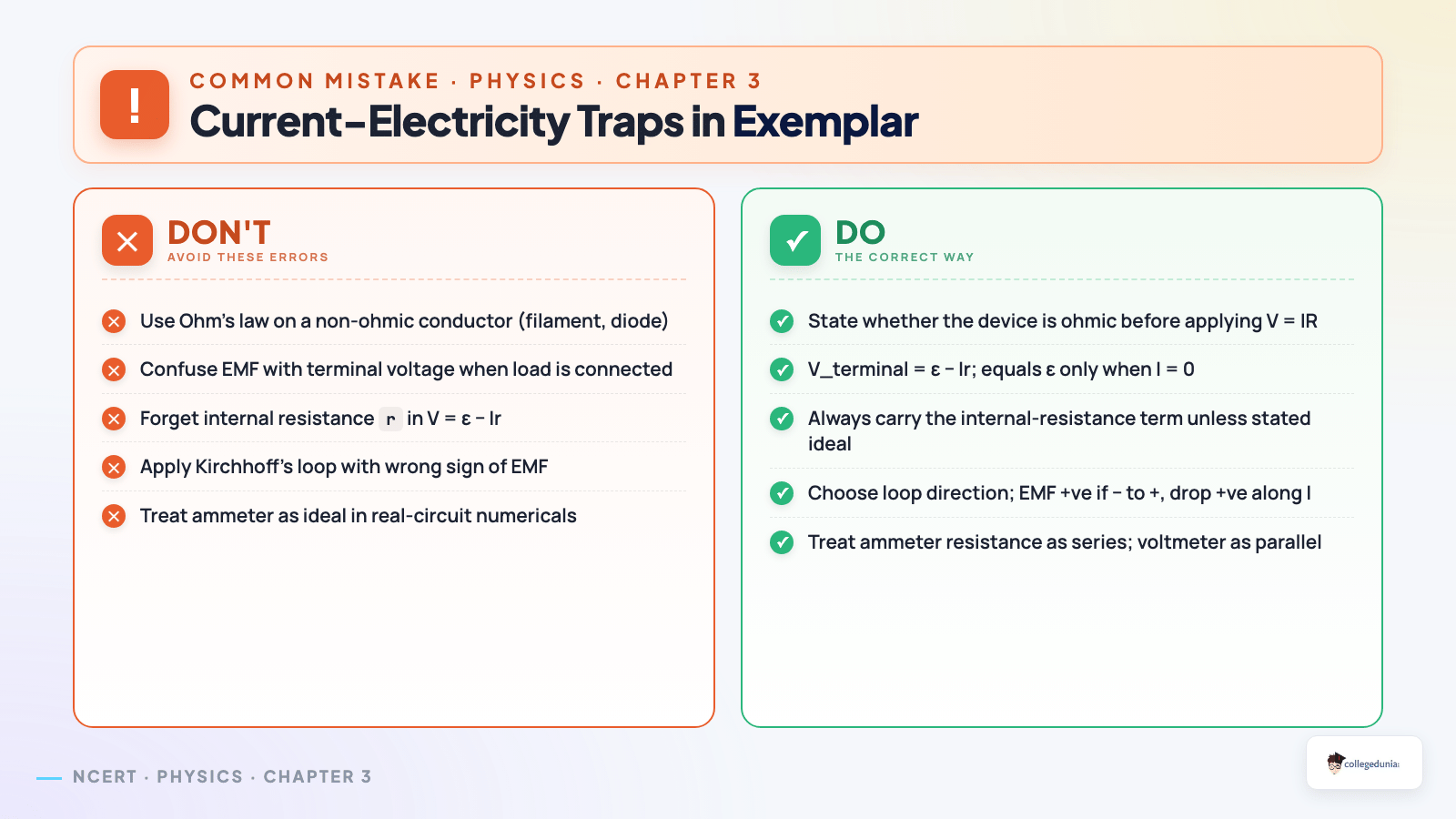

Comments