Physics Mentor, SRM Institute | Updated on - Jul 21, 2026
These Class 12 Physics Chapter 9 Ray Optics and Optical Instruments NCERT Solutions help students see how exam questions are framed. Every answer follows the latest NCERT guidelines for CBSE, JEE, and NEET. This page hosts the full solutions PDF with step-wise and expert solutions for each question.
CBSE Boards: This is a high-weightage chapter, worth about 7 marks. Expect one 5-mark derivation plus one 2-mark question.
JEE Main: 4 to 5 per cent, with two to three questions per shift on lens combinations, prism dispersion, and telescope magnification.
NEET: Usually 2 to 3 formula-based questions on the mirror formula, Snell's law, and the human eye every year.
The solutions provided below for Ray Optics and Optical Instruments questions align with NCERT Chapter 9 content. Each solution is prepared well by the Collegedunia Subject Matter Experts keeping CBSE Boards, JEE Main and NEET 2027 students in mind.
You can find the complete Class 12 physics ray optics NCERT solutions, including every back-exercise, the lens-maker's derivation, the compound microscope and astronomical telescope problems, and worked numericals on optical instruments class 12, in the article below.
Exercise Breakdown for Class 12 Ray Optics NCERT Solutions
The chapter carries 31 back exercises plus 11 in-text solved examples in the new edition. Exercises 9.1 to 9.10 are conceptual or single-step numericals on reflection and refraction; from exercise 9.11 onward, every problem is a multi-step numerical worth 3 to 5 marks.
Lens-maker's formula - focal length from geometry + refractive index.
Ray Optics Weightage Compared Across Class 12 Physics Chapters
The table below compares the average CBSE marks for Chapter 9 with other Class 12 Physics chapters. Chapters 1, 2, and 9 share the top weightage of about 7 marks each.
Chapter
Topic
Avg CBSE Marks
Ch 1
Electric Charges and Fields
6 marks
Ch 2
Electrostatic Potential and Capacitance
7 marks
Ch 3
Current Electricity
7 marks
Ch 4
Moving Charges and Magnetism
6 marks
Ch 5
Magnetism and Matter
3 marks
Ch 6
Electromagnetic Induction
5 marks
Ch 7
Alternating Current
6 marks
Ch 8
Electromagnetic Waves
2 marks
Ch 9
Ray Optics and Optical Instruments
7 marks
Ch 10
Wave Optics
5 marks
Ch 11
Dual Nature of Radiation and Matter
4 marks
Ch 12
Atoms
3 marks
Ch 13
Nuclei
3 marks
Ch 14
Semiconductor Electronics
6 marks
Important Derivations Index for Class 12 Ray Optics
Seven derivations carry most of the marks in this chapter. The same seven come up in CBSE, JEE Main, and NEET every year, so revise each one with its sign-convention step.
Derivation
Marks (CBSE)
Last Major Appearance
Mirror formula 1/v + 1/u = 1/f
3
CBSE 2024
Refraction at a spherical surface (n_2/v minus n_1/u = (n_2 minus n_1)/R)
3
CBSE 2023, NEET 2025
Lens-maker's formula (1/f = (n minus 1)(1/R_1 minus 1/R_2))
All Formulas of Ray Optics Class 12: Quick-Reference Table
The 18 formulas below cover every numerical in this chapter. The same formulas come up in CBSE, JEE Main, and NEET. The PDF card above has the same table on one page.
Common Mistakes Students Make in Chapter 9 Physics Class 12
These four mistakes show up in CBSE scripts every year. Each one can turn a 5-marker into a 2 or 3, so check for them while you revise.
Mistake 1: Inconsistent sign convention. Always use Cartesian: distances measured against the light direction are negative; heights above the principal axis are positive. CBSE marks the sign-step independently of the final numerical.
Mistake 2: Swapping the mirror formula and lens formula. Mirror: 1/v + 1/u = 1/f. Lens: 1/v minus 1/u = 1/f. The sign of the u-term is the only difference.
Mistake 3: Forgetting that the lens-maker's formula uses (n minus 1), not just n. The (n minus 1) factor is what makes a vacuum-surrounded lens with n = 1 have infinite focal length (= no lens).
Mistake 4: Using the telescope magnification M = f_o / f_e without checking adjustment. The formula is exact only for "normal adjustment" (final image at infinity); for near-point adjustment, M = (f_o / f_e)(1 + f_e / D).
Each one costs 1 to 3 marks even when the rest of the working is correct.
Other Resources for Class 12 Ray Optics and Optical Instruments
Use these other Collegedunia resources for Class 12 Physics Chapter 9. You are reading the NCERT Solutions page now.
All NCERT Solutions for Class 12 Physics Chapter 9 Ray Optics and Optical Instruments with Step-by-Step Solutions
Every question of NCERT Class 12 Physics Ray Optics and Optical Instruments is listed below with its full Solution and Expert Solution hidden inside collapsible tabs. Click Check Solution to reveal the step-by-step working; click Expert Solution for the expanded explanation.
Q 9.1
A small candle, 2.5 cm in size, is placed at 27 cm in front of a concave mirror of radius of curvature 36 cm. At what distance from the mirror should a screen be placed to obtain a sharp image? Describe the nature and size of the image. If the candle is moved closer to the mirror, how would the screen have to be moved?
Check Solution
Expert Solution
What is being asked. Find the image position for a candle placed in front of a concave mirror, and check whether the image is real (catchable on a screen) or virtual, magnified or diminished, erect or inverted.
Given.
Object height, h1 = +2.5 cm (above the axis, so positive)
Object distance, u = -27 cm (object is in front of the mirror - negative in the Cartesian convention)
Radius of curvature, R = -36 cm (centre of curvature is on the same side as the object for a concave mirror - negative)
Focal length, f = R/2 = -18 cm
Concept used - mirror formula and magnification.
1
v
+
1
u
=
1
f
, m =
h2
h1
= -
v
u
.
The mirror formula relates the image distance v, object distance u and focal length f. Magnification m tells us how tall the image is and (by its sign) whether it is inverted (m<0) or erect (m>0).
Step 1 - rearrange for v.
1
v
=
1
f
-
1
u
.
Step 2 - substitute the numbers.
1
v
=
1
-18
-
1
-27
= -
1
18
+
1
27
.
Step 3 - common denominator (LCM of 18 and 27 is 54).
1
v
= -
3
54
+
2
54
= -
1
54
.
Step 4 - invert.
v = -54 cm.
The minus sign means the image is on the same side as the object (in front of the mirror) - so it is REAL and can be caught on a screen 54 cm from the mirror.
Step 5 - magnification.
m = -
v
u
= -
(-54)
(-27)
= -2.
The negative sign means the image is inverted; the magnitude 2 means the image is twice as tall as the object.
Step 6 - image height.
h2 = m h1 = (-2)(2.5) = -5 cm.
So the image is 5 cm tall, inverted (below the axis).
Step 7 - what if the candle moves closer to the mirror? Move it from 27 cm toward the focus at 18 cm. As u → -f, the mirror formula gives v → ∞. So the screen must be moved farther and farther away to catch the image; once the candle is inside the focus (|u| < 18 cm), no real image forms - the image becomes virtual and the screen cannot catch it at all.
Final answer.
v = -54 cm (real, in front of mirror), h2 = -5 cm (inverted, magnified 2×).
Screen at 54 cm from the mirror. As the candle approaches the focus, the screen must be moved away to infinity.
DR
Dr. Rajesh Kumar
Ph.D. Physics, IIT Delhi
Verified Expert
Why the Cartesian sign convention matters. Many students get a confused mix of positives and negatives because they swap conventions mid-problem. Lock it in once: (i) light travels from object to mirror along the negative direction (so u is negative for a real object in front of the mirror); (ii) for a concave mirror, both f and R are negative; (iii) for a convex mirror, both are positive. If your final v comes out negative, the image is real and in front; positive means virtual and behind.
Graphical ray-tracing check. Draw three principal rays from the candle tip: (i) a ray parallel to the axis that reflects through the focus; (ii) a ray through the centre of curvature that returns along itself; (iii) a ray through the focus that reflects parallel to the axis. They converge 54 cm in front of the mirror, below the axis, twice as tall - exactly matching our algebra.
Common mistake. Writing f = +18 cm for a concave mirror because "focal length is positive." The sign depends on the convention; in Cartesian convention used by NCERT, concave-mirror focal length is negative. If you forget, you can still get the right magnitude - but the sign analysis (real vs virtual) will be wrong.
Real-world link - shaving and make-up mirrors. Concave mirrors with object inside focus produce an erect, enlarged virtual image - that's why they're used for shaving and applying make-up. Beyond focus, they form a real, inverted image - the principle behind reflecting telescopes and dental mirrors used to "image" a tooth onto the dentist's eye.
JEE/NEET twist. Examiners often phrase the question as "the candle is moved between centre of curvature and focus": there 2f < |u| < f (i.e., 36 > |u| > 18), and the image forms beyond 2f, real, inverted, magnified - exactly the configuration here at |u|=27 cm. Memorise the six standard positions for a concave mirror and you'll never need the formula in MCQs.
Q 9.2
A 4.5 cm needle is placed 12 cm away from a convex mirror of focal length 15 cm. Give the location of the image and the magnification. Describe what happens as the needle is moved farther from the mirror.
Check Solution
Expert Solution
Given.
Object height, h1 = +4.5 cm
Object distance, u = -12 cm
Focal length, f = +15 cm (convex mirror - positive)
Concept used - mirror formula.
1
v
+
1
u
=
1
f
, m=-
v
u
=
h2
h1
.
A convex mirror has a virtual focus behind it; light only appears to diverge from there. Such a mirror always produces a virtual, erect, diminished image for a real object - but we'll prove it from the formula.
Step 1 - solve for v.
1
v
=
1
f
-
1
u
=
1
15
-
1
-12
=
1
15
+
1
12
.
Step 2 - common denominator (LCM 60).
1
v
=
4
60
+
5
60
=
9
60
=
3
20
.
Step 3 - invert.
v=
20
3
cm ≈ +6.7 cm.
The positive sign means the image is behind the mirror - so it is VIRTUAL and erect; a screen cannot catch it.
Step 4 - magnification.
m=-
v
u
=-
20/3
-12
=
20
36
=
5
9
≈ 0.56.
Step 5 - image height.
h2 = m h1 =
5
× 4.5 = 2.5 cm.
9
The positive sign confirms the image is erect; the magnitude 0.56 means it is diminished - about half the size.
Step 6 - as the needle moves away. Take u→ -∞. The mirror formula gives 1/v → 1/f so v→ +f = +15 cm. The image moves toward the focus behind the mirror, but never reaches it, while m → 0 - the image becomes a tiny dot at the focus.
Final answer.
v=+6.7 cm (virtual, behind mirror), m=0.56, h2 = 2.5 cm (erect, diminished).
As the needle moves away, the image shrinks and recedes toward the focus, never crossing it.
DA
Dr. Anita Sharma
Ph.D. Physics, University of Delhi
Verified Expert
Why convex mirrors are everywhere in cars and shops. Two virtues: (i) they always form an erect, diminished virtual image - so a wide field-of-view is compressed into a small mirror, perfect for blind-spot detection; (ii) the image distance is bounded (0 < v < f), so distant objects don't "jump out" at you - they smoothly compress toward the focus.
The "objects in mirror are closer than they appear" warning. A convex mirror makes objects look smaller, which our brain interprets as farther away. So the actual distance to the car behind you is less than your gut estimate - hence the legal warning on every passenger-side mirror in the US/EU.
Alternative - graphical method. For a convex mirror, draw: (i) a ray parallel to the axis that reflects as if coming from the (virtual) focus behind the mirror; (ii) a ray heading toward the centre of curvature that returns along itself. These two reflected rays diverge - extend them backward (dashed lines) until they meet behind the mirror; that's where the virtual image forms.
Common mistake. Writing f = -15 cm for a convex mirror. In the Cartesian convention, convex-mirror f is positive; the focus is behind the mirror, in the +ve direction. Equally common: forgetting to take the absolute value when reporting magnification - m here is a fraction 5/9, not negative.
JEE/NEET tip. For a convex mirror, since f>0 and u<0, the formula 1/v = 1/f - 1/u always gives 1/v > 0, i.e., v is always positive. This algebraically proves: a convex mirror always forms a virtual image for a real object - no exceptions.
Q 9.3
A tank is filled with water to a height of 12.5 cm. The apparent depth of a needle lying at the bottom of the tank is measured by a microscope to be 9.4 cm. What is the refractive index of water? If water is replaced by a liquid of refractive index 1.63 up to the same height, by what distance would the microscope have to be moved to focus on the needle again?
Check Solution
Expert Solution
Setup. A needle at the bottom of a tank looks closer to the top surface than it really is, because rays bend (refract) when they leave the water into air. We use the "apparent depth" relation.
Given.
Real depth, dreal=12.5 cm
Apparent depth in water, dapp=9.4 cm
For part (b): replaced liquid has μ' = 1.63
Concept used - apparent depth. When looking nearly straight down through a transparent medium of refractive index μ into air,
μ =
real depth
.
apparent depth
The microscope is focused at the apparent depth, where the rays seem to come from.
Step 1 - refractive index of water.
w =
12.5
9.4
≈ 1.33.
This matches the textbook value for water w ≈ 1.33. Good check.
Step 2 - apparent depth in the new liquid.
dapp' =
dreal
= 12.51.63 ≈ 7.67 cm.
μ'
Step 3 - by how much must the microscope shift? Initially the microscope is focused at 9.4 cm (apparent depth in water). After replacing the water with the denser liquid, the needle appears at 7.67 cm - closer to the surface. The microscope must move down by
Δ d = 9.4 - 7.67 = 1.73 cm ≈ 1.7 cm.
Final answer.
w ≈ 1.33, Δ d ≈ 1.73 cm (microscope moves toward the surface).
DS
Dr. Suresh Iyer
Ph.D. Theoretical Physics, TIFR Mumbai
Verified Expert
Where the apparent-depth formula comes from. Apply Snell's law to a near-vertical ray leaving the bottom of the tank. For small angles, sinθθ. A ray from the needle at real depth d hitting the surface at horizontal distance x has tan1 = x/d inside, tan2 = x/dapp outside. Snell: μ sin1 = sin2. Small-angle: μ· x/d = x/dapp, giving μ = d/dapp. This is only valid for paraxial viewing (looking straight down) - at oblique angles, apparent depth is more complicated.
Why the microscope moves DOWN, not up. The new liquid is denser (μ'=1.63 > 1.33), so it bends light more - the needle's image appears even closer to the surface than in water. To re-focus on the new, shallower apparent depth, the microscope's objective must descend (toward the water surface).
Real-world link - fishing. Spearing a fish underwater is hard because the fish appears higher than it actually is. Experienced fishers aim below the apparent position. Conversely, looking up from underwater, the world above looks compressed into a circle (Snell's window) due to total internal reflection at the boundary.
Common mistake. Reporting the shift as 12.5 - 7.67 (i.e., from real depth to new apparent depth). But the microscope was originally focused at the water's apparent depth 9.4 cm, not the real depth - so the relevant difference is 9.4 - 7.67, not 12.5 - 7.67.
Q 9.4
Figures 9.27(a) and (b) show refraction of a ray in air incident at 60° with the normal to a glass-air and water-air interface, respectively. Predict the angle of refraction in glass when the angle of incidence in water is 45° with the normal to a water-glass interface [Fig. 9.27(c)].
Check Solution
Expert Solution
Reading the figure. From (a): in air → glass, incidence 60°, refraction 35°. From (b): in air → water, incidence 60°, refraction 47°. We need the angle of refraction in glass when light goes from water at 45°.
Concept used - Snell's law.
1 sin1 = 2 sin2.
This holds at every interface. By chaining the refractive indices, we connect glass and water through air.
Step 1 - find g (refractive index of glass relative to air) from Fig. (a).
ag =
sin 60°
sin 35°
=
0.866
0.574
≈ 1.51.
Step 2 - find w (refractive index of water relative to air) from Fig. (b).
aw =
sin 60°
sin 47°
=
0.866
0.731
≈ 1.18.
(NCERT uses these numbers; the standard "book" value for water is 1.33, but here we stick with what the figure gives us.)
Step 3 - relative refractive index of glass with respect to water.
wg =
ag
aw
=
1.51
1.18
≈ 1.28.
Step 4 - apply Snell's law at the water-glass interface.
w sin 45° = g sing, ⇒ sing =
w
g
sin 45° =
1
wg
sin 45°.
Step 5 - substitute.
sing =
1
× 0.707 = 0.552.
1.28
Step 6 - invert sine.
g = sin-1(0.552) ≈ 38.5° ≈ 38°41'.
Final answer.
g ≈ 38.5°.
PM
Prof. Meera Nair
Ph.D. Experimental Physics, IISc Bangalore
Verified Expert
Why chain through air. Refractive indices are defined relative to vacuum or, with ∼ 0.03% error, to air. Whenever you go from medium 1 to medium 2, the relevant ratio is 12 = 2/1. Memorise: μ for water ≈ 1.33, glass ≈ 1.5, diamond ≈ 2.42. The "denser" medium larger μ bends light toward the normal.
Alternative - direct Snell's chain. You can also write w sin 45° = g sing directly, then plug in textbook values: 1.33 × 0.707 = 1.5 sing, giving sing = 0.627, g ≈ 38.8° - same answer to one decimal. The minor discrepancy with our 38.5° comes from using figure-derived μ's rather than book values.
Real-world link - fibre optics. Glass-to-water refraction is the same physics that lets glass fibres trap light. As long as the angle exceeds the critical angle, total internal reflection kicks in and the ray bounces along the fibre with negligible loss. We'll explore this in Q 9.17.
Common mistake. Confusing "refractive index of glass with respect to water" with the ratio the other way. The rule is: ab = va/vb = b/a (where the LHS uses "with respect to" and the RHS uses absolute indices). Pure memorisation often goes wrong - always derive from Snell's law.
Q 9.5
A small bulb is placed at the bottom of a tank containing water to a depth of 80 cm. What is the area of the surface of water through which light from the bulb can emerge? The refractive index of water is 1.33. (Consider the bulb to be a point source.)
Check Solution
Expert Solution
Setup. A point source at the bottom emits rays in all directions. Each ray hits the water surface; only those striking at angles less than the critical angle c escape into the air. Rays steeper than c are totally internally reflected back. The escaping rays form a bright "cone of light" - and the cone illuminates a CIRCLE on the surface.
Concept used - critical angle.
sinc =
1
= nrarerndenser.
μ
At c the refracted ray skims the surface refraction angle =90°; beyond it, total internal reflection.
Given. Depth h=80 cm=0.8 m, μ=1.33.
Step 1 - find the critical angle.
sinc=
1
=0.752, c=sin-1(0.752)≈ 48.75°.
1.33
Step 2 - geometry of the lit circle. The bulb sits at depth h. Draw the limiting ray: it leaves the bulb, hits the water surface at angle c from the vertical (normal). The horizontal distance from directly-above-the-bulb to the point it strikes the surface is the radius r of the lit circle:
tanc =
r
, r = h tanc.
h
Step 3 - compute tanc. Use sinc = 0.752, so cosc = √1-0.7522=√1-0.566=√0.434=0.659. Therefore
The bulb illuminates a circular patch of about 2.6 m2 on the water surface; everything outside the patch is dark above.
DS
Dr. Sneha Iyer
Ph.D. Physics, IISc Bangalore
Verified Expert
Snell's window. If you're swimming underwater and look up, you see the entire world above compressed into a circular patch overhead - this is the same effect. Outside the patch, the water surface acts like a mirror, reflecting the bottom of the pool. Fish use this all the time to spot prey above and predators on the surface.
Compact formula. Combine the steps: r = htanc, and tanc = sinc/√1-sin2c = 1/μ/√1-1/μ2 = 1/√μ2-1. So
Why deeper bulbs light bigger patches. The area scales as h2 - doubling the depth quadruples the lit patch. But the intensity (power per area) drops correspondingly - Newton's inverse-square law of light in disguise.
Common mistake. Computing c from sinc = μ/1 = 1.33, which gives an impossible "sin > 1." The convention is: critical angle is measured in the denser medium when going to the rarer one. Always set up sinc = nrarer/ndenser - less than 1.
Q 9.6
A prism is made of glass of unknown refractive index. A parallel beam of light is incident on a face of the prism. The angle of minimum deviation is measured to be 40°. What is the refractive index of the material of the prism? The refracting angle of the prism is 60°. If the prism is placed in water (refractive index 1.33), predict the new angle of minimum deviation of a parallel beam of light.
Check Solution
Expert Solution
Given.
Refracting angle of prism, A = 60°
Angle of minimum deviation in air, Dm = 40°
Refractive index of water, w = 1.33
Concept used - prism formula at minimum deviation. At minimum deviation, light passes symmetrically through the prism, and
μ =
sin((A+Dm)/2)
.
sin(A/2)
This is the standard prism formula. Here μ is the refractive index of the prism relative to the surrounding medium.
The prism deviates light much less when immersed in water, because the glass-water optical contrast is smaller than glass-air contrast.
DV
Dr. Vivek Khanna
Ph.D. Physics, IIT Bombay
Verified Expert
Why immersion in water reduces deviation. Deviation depends on the ratio of refractive indices at the interface. In air, the ratio is 1.53/1 = 1.53; in water it's 1.53/1.33 ≈ 1.15. Smaller contrast = less bending. If you could match the surrounding medium's index exactly to the glass medium = glass, the prism would become "invisible" - no refraction at all. This is how immersion oil works in microscopy.
Alternative - small-angle limit. For thin prisms (small A), Dm ≈ μ - 1A. In air: Dm = (1.53-1)× 60° = 31.8° - close to 40° but the formula is only approximate. In water: Dm' = (1.152-1)× 60° = 9.1° - close to our exact 10°. The thin-prism formula is great for quick estimates.
Real-world link - prism spectroscopes. The dispersive power of a prism (separating colours) comes from the wavelength-dependence of μ. When you immerse a prism in water, dispersion drops too - that's why immersion liquids are used to "tune" the working bandwidth of optical instruments.
Common mistake. Using g (1.53) directly in the formula for water-immersed case. The formula always uses the relative index between prism and surroundings, not the absolute index.
Q 9.7
Double-convex lenses are to be manufactured from a glass of refractive index 1.55, with both faces of the same radius of curvature. What is the radius of curvature required if the focal length is to be 20 cm?
Check Solution
Expert Solution
Concept used - lensmaker's equation. For a thin lens in air with refractive index μ, and surfaces of radii R1, R2,
1
f
= (μ-1)(
1
R1
-
1
R2
).
Sign convention: R is positive if the centre of curvature is on the outgoing (right) side, negative if on the incoming (left) side.
Given.μ = 1.55, f = +20 cm (converging double-convex lens).
Step 1 - assign signs to R1 and R2. For a double-convex (biconvex) lens with light incident from the left:
– Surface 1 bulges to the left (its centre of curvature is on the right) → R1 = +R.
– Surface 2 bulges to the right (its centre of curvature is on the left) → R2 = -R.
The problem says both faces have the same radius of curvature; we'll call its magnitude R.
Step 2 - plug into lensmaker's formula.
1
f
= (μ-1)(
1
+R
-
1
-R
) = (μ-1)(
1
R
+
1
R
) =
2(μ-1)
R
.
Step 3 - solve for R.
R = 2(μ-1) f.
Step 4 - substitute numbers.
R = 2 (1.55-1) (20) = 2 × 0.55 × 20 = 22 cm.
Final answer.
R = 22 cm.
Each surface must be ground to a radius of curvature of 22 cm.
DR
Dr. Rajesh Kumar
Ph.D. Physics, IIT Delhi
Verified Expert
Why the lens needs a bigger R than f. Notice R = 22 cm is larger than f = 20 cm. In a low-index glass μ = 1.55, the bending is mild, so to achieve a short focal length we need a fairly flat (large-R) surface combination. If you use a higher-index material e.g. dense flint, μ = 1.7, R = 2(0.7)(20) = 28 cm - wait, that's larger. Let me re-examine: actually R = 2μ-1fincreases with μ, so higher-index glass needs flatter surfaces to give the same focal length. That's why high-index camera lenses can be thinner.
Alternative method - thin-lens equation as a check. Place an object at u = -40 cm (twice the focal length). For an ideal thin lens with f = 20, we expect v = +40 cm and m = -1. Plug into 1/v - 1/u = 1/f: 1/v = 1/20 - 1/40 = 1/40, so v = +40 cm. Check.
Common mistake. Forgetting the sign of R2 (writing both positive). That gives 1/f = μ-1(0) = 0 - infinite focal length, which is nonsense. The Cartesian convention is the only way to keep the signs straight.
Real-world link - Aspheric lenses. In premium cameras and eyeglasses, the spherical surfaces (constant R) are replaced by aspheric surfaces (varying curvature) to reduce spherical aberration. Lensmaker's formula no longer directly applies - one has to solve the full wave equation numerically.
Q 9.8
A beam of light converges at a point P. Now a lens is placed in the path of the convergent beam 12 cm from P. At what point does the beam converge if the lens is (a) a convex lens of focal length 20 cm, and (b) a concave lens of focal length 16 cm?
Check Solution
Expert Solution
The trick - virtual object. Light is already converging toward P when it meets the lens. So for the lens, P acts as a virtual object on the far side. In the Cartesian convention, virtual object means u > 0 - measured along the direction of light propagation, on the outgoing side.
(a) Convex lens, f = +20 cm.
Step 1 - set up. Virtual object at u = +12 cm. Use thin-lens formula 1/v - 1/u = 1/f.
Step 2 - substitute.
1
v
=
1
f
+
1
u
=
1
20
+
1
12
.
Step 3 - common denominator (LCM 60).
1
v
=
3
60
+
5
60
=
8
60
=
2
15
.
Step 4 - invert.
v =
15
2
= 7.5 cm.
Positive, on the same side as P. So with the convex lens, the beam converges 7.5 cm past the lens (closer than P).
(b) Concave lens, f = -16 cm.
Step 1 - substitute.
1
v
=
1
-16
+
1
12
= -
1
16
+
1
12
.
Step 2 - common denominator (LCM 48).
1
v
= -
3
48
+
4
48
=
1
48
.
Step 3 - invert.
v = +48 cm.
With the concave lens, the beam converges 48 cm past the lens (farther than P) - the lens has weakened the convergence.
Final answer.
(a) v = +7.5 cm, (b) v = +48 cm.
DA
Dr. Anita Sharma
Ph.D. Physics, University of Delhi
Verified Expert
Why a concave lens shifts the focus farther. Concave lenses diverge; they "push out" the convergence point. In (b), the original beam was converging to a point 12 cm past the lens, but the concave lens makes the rays diverge a little, delaying convergence to 48 cm. A converging beam can never be made to diverge entirely by a single thin diverging lens unless the diverging power exceeds the original convergence.
Why a convex lens brings it closer. A convex lens adds convergence to the already-convergent beam, pulling the focus closer to the lens - here, from 12 cm down to 7.5 cm.
Alternative method - power addition. Define the original beam's "power" as that of a converging system focusing at 12 cm: P1 = 1/0.12 = 8.33 D. Add the lens power. Convex f=20 cm: P2 = 5 D, total 13.33 D, new focus at 1/13.33 = 0.075 m = 7.5 cm. Concave f=-16 cm: P2 = -6.25 D, total 2.083 D, new focus at 0.48 m = 48 cm. Power addition is a fast shortcut for thin-lens combinations.
Common mistake. Writing u = -12 cm by reflex. Virtual object - light is converging toward the lens - gives positive u. The sign convention treats the object location relative to the direction of incident light, not "in front" or "behind."
Q 9.9
An object of size 3.0 cm is placed 14 cm in front of a concave lens of focal length 21 cm. Describe the image produced by the lens. What happens if the object is moved further away from the lens?
Check Solution
Expert Solution
Given.
Object height, h1 = +3.0 cm
Object distance, u = -14 cm
Focal length, f = -21 cm (concave lens → diverging → negative)
Concept used - thin-lens formula.
1
v
-
1
u
=
1
f
, m =
v
u
=
h2
h1
.
For a concave lens, f < 0, and a real object (u < 0) always produces a virtual, erect, diminished image - let's prove it.
Step 1 - solve for v.
1
v
=
1
f
+
1
u
=
1
-21
+
1
-14
= -
1
21
-
1
14
.
Step 2 - common denominator (LCM 42).
1
v
= -
2
42
-
3
42
= -
5
42
.
Step 3 - invert.
v = -
42
5
= -8.4 cm.
Negative - image is on the same side as the object, i.e., virtual, erect.
Step 4 - magnification.
m =
v
u
=
-8.4
-14
= 0.6.
Positive (erect), < 1 (diminished).
Step 5 - image size.
h2 = m h1 = 0.6 × 3.0 = 1.8 cm.
Step 6 - as the object moves farther. Let u→ -∞. Then 1/v → 1/f = -1/21, so v → -21 cm; the image moves toward the focus on the object side. Meanwhile m→ 0 - image shrinks to zero size. So as object recedes, image moves toward focus and gets smaller, but stays virtual.
Final answer.
v = -8.4 cm, h2 = +1.8 cm (virtual, erect, diminished).
DS
Dr. Suresh Iyer
Ph.D. Theoretical Physics, TIFR Mumbai
Verified Expert
The "iron rule" for concave lenses. For ANY real object placed in front of a concave lens, the image is always: virtual, erect, diminished, and located between the optical centre and the focus on the same side as the object. You can prove this algebraically - f<0 and u<0 always give 1/v < 0, and |v| < |f| for any finite |u|.
Real-world link - diverging eyeglasses. Myopia (short-sightedness) is corrected with diverging (concave) lenses. The lens forms a virtual, diminished image of distant objects at a distance the myopic eye can focus - typically a few metres in front. The eye then sees this nearby virtual image rather than the actual distant object.
Alternative - ray diagram. Draw: (i) parallel ray refracts as if diverging from focus on object side; (ii) ray through optical centre passes undeviated. Extend the diverging rays backwards (dashed) - they meet on the object side, between focal point and centre. Always a virtual image.
Common mistake. Using 1/v + 1/u = 1/f (the mirror formula) instead of 1/v - 1/u = 1/f (the lens formula). The sign on 1/u flips between mirror and lens formulas in the NCERT convention. Memorise both separately.
Q 9.10
What is the focal length of a convex lens of focal length 30 cm in contact with a concave lens of focal length 20 cm? Is the system a converging or a diverging lens? Ignore thickness of the lenses.
Check Solution
Expert Solution
Concept used - combination of thin lenses in contact. When two thin lenses focal lengths f1, f2 are placed in contact, the combined focal length f is given by
1
f
=
1
f1
+
1
f2
.
Equivalently, in terms of powers P = 1/f in metres,
Pnet = P1 + P2.
Given. Convex lens: f1 = +30 cm; concave lens: f2 = -20 cm.
Step 1 - write the combination.
1
f
=
1
30
+
1
-20
=
1
30
-
1
20
.
Step 2 - common denominator (LCM 60).
1
f
=
2
60
-
3
60
= -
1
60
.
Step 3 - invert.
f = -60 cm.
Step 4 - interpret. Negative focal length ⇒ the combination behaves as a diverging lens. So the concave lens "wins" - its power is greater than that of the convex lens, and the net system diverges.
Final answer.
f = -60 cm, diverging system.
PM
Prof. Meera Nair
Ph.D. Experimental Physics, IISc Bangalore
Verified Expert
Why the combination diverges even though one lens converges. Power is P = 1/f. The convex lens has P1 = +1/0.30 = +3.33 D; the concave lens has P2 = -1/0.20 = -5 D. Adding: P = 3.33 - 5 = -1.67 D⇒f = -0.60 m = -60 cm. The "stronger" lens (in terms of |P|) dominates the net behaviour.
Real-world link - achromatic doublets. Real telescope objectives combine a convex (crown) and a concave (flint) lens in contact to cancel chromatic aberration. The two lenses are chosen so their net focal length is finite (converging) while their net dispersion is zero. The combination formula is the starting point for that design.
Alternative - direct power addition.P1 + P2 = 3.33 - 5 = -1.67 D; f = 1/P = -60 cm. Faster than the reciprocal arithmetic.
Common mistake. Forgetting the sign of f2 (the concave lens). Once you write 1/f = 1/30 + 1/(-20), the sign takes care of itself. Skipping the sign and writing 1/30 + 1/20 gives f = +12 cm - wrong by both magnitude and sign.
Q 9.11
A compound microscope consists of an objective lens of focal length 2.0 cm and an eyepiece of focal length 6.25 cm separated by a distance of 15 cm. How far from the objective should an object be placed to obtain the final image at (a) the least distance of distinct vision 25 cm, and (b) at infinity? What is the magnifying power of the microscope in each case?
Check Solution
Expert Solution
Concept used - compound microscope. A compound microscope has two converging lenses: objective (short focal length) forms a real, inverted, magnified image of the tiny object, which the eyepiece (acting as a simple magnifier) then magnifies further. The final image can be at infinity (relaxed eye) or at the near point D = 25 cm (maximum magnification).
Given.fo = +2.0 cm, fe = +6.25 cm, L = 15 cm (lens separation), D = 25 cm.
(a) Final image at near point ve = -25 cm, erect virtual image relative to eyepiece.
Step 1 - locate the intermediate image (object for eyepiece). Apply lens formula to eyepiece:
1
ve
-
1
ue
=
1
fe
⇒
1
ue
=
1
ve
-
1
fe
=
1
-25
-
1
6.25
.
LCM 25:
1
ue
= -
1
25
-
4
25
= -
5
25
= -
1
5
.
ue = -5 cm.
Step 2 - locate the object for the objective. Distance from objective to intermediate image: vo = L - |ue| = 15 - 5 = 10 cm. So vo = +10 cm. Apply lens formula to objective:
1
uo
=
1
vo
-
1
fo
=
1
10
-
1
2
.
LCM 10:
1
uo
=
1
10
-
5
10
= -
4
10
. So uo = -2.5 cm.
Step 3 - magnification.
m = mo · me =
vo
uo
(1 +
D
fe
) =
10
-2.5
(1+
25
6.25
) = -4 × (1+4) = -20.
Magnitude |m|=20; the negative sign tells us the final image is inverted relative to the object.
(b) Final image at infinity (relaxed eye).
Step 1 - eyepiece. For final image at ∞, the intermediate image must be at the focus of the eyepiece, i.e., ue = -fe = -6.25 cm.
Step 2 - objective.vo = L - 6.25 = 15 - 6.25 = 8.75 cm.
1
uo
=
1
vo
-
1
fo
=
1
8.75
-
1
2
= 0.1143 - 0.5 = -0.3857.
uo = -
1
≈ -2.59 cm.
0.3857
Step 3 - magnification.
m =
vo
uo
·
D
fe
=
8.75
-2.59
×
25
6.25
= -3.38 × 4 = -13.5.
Final answer.
(a) Object at 2.5 cm in front of objective; magnifying power |m| = 20.
(b) Object at ≈ 2.59 cm in front of objective; magnifying power |m| ≈ 13.5.
DV
Dr. Vivek Khanna
Ph.D. Physics, IIT Bombay
Verified Expert
Why near-point setting gives bigger magnification. The eyepiece's "near-point" magnification is 1 + D/fe, versus the "infinity" magnification D/fe. The extra +1 gives a fractional boost ∼ fe/D - small but noticeable. Trade-off: near-point viewing tires the eye ciliary muscles strain to focus at 25 cm; infinity viewing is more relaxing. Microscopists set their instrument for relaxed viewing during long observations.
Tube length and "tube length convention." Many textbooks use L ≈ tube length ≈vobecause |uo|≪ vo. Approximate magnification:
mnear point ≈ -
L
(1+Dfe), m∞ ≈ -Lfo·Dfe.
fo
NCERT often quotes these approximate formulas. They're accurate to a few percent.
Real-world link - modern microscopes. Today's compound microscopes use objective lenses with very short focal lengths ∼ 2 mm at 100× and a "tube lens" rather than a simple eyepiece. The intermediate image forms at a precise location, allowing for parallel beam paths between objective and tube lens - much easier to insert filters, beam splitters, etc.
Common mistake. Treating the eyepiece distance as ve = +25 cm for near-point viewing. The virtual image is on the same side as the object of the eyepiece - so ve = -25 cm in the Cartesian convention.
Q 9.12
A person with a normal near point 25 cm using a compound microscope with an objective of focal length 8.0 mm and an eyepiece of focal length 2.5 cm can bring an object placed at 9.0 mm from the objective in sharp focus. What is the separation between the two lenses? Calculate the magnifying power of the microscope.
Check Solution
Expert Solution
Given.
fo = 8.0 mm = 0.8 cm, uo = -9.0 mm = -0.9 cm
fe = 2.5 cm, D = 25 cm
Assume final image at near point (most magnification, standard).
Step 1 - image distance for objective.
1
vo
=
1
fo
+
1
uo
=
1
0.8
+
1
-0.9
= 1.25 - 1.111 = 0.139.
vo =
1
= 7.2 cm.
0.139
So the objective produces a real, inverted, magnified image 7.2 cm behind itself.
Step 2 - find object distance for eyepiece. Final image at ve = -25 cm.
1
ue
=
1
ve
-
1
fe
=
1
-25
-
1
2.5
= -0.04 - 0.4 = -0.44.
ue = -
1
= -2.273 cm.
0.44
Step 3 - separation between lenses. The intermediate image is at vo = 7.2 cm behind objective and serves as the eyepiece's object at |ue| = 2.273 cm in front of the eyepiece. Therefore lens separation
L = vo + |ue| = 7.2 + 2.273 = 9.47 cm.
Step 4 - magnification of objective.
mo =
vo
= 7.2-0.9 = -8.
uo
Step 5 - magnification of eyepiece.
me = 1 +
D
= 1 + 252.5 = 1+10 = 11.
fe
Step 6 - total magnification.
m = mo me = -8 × 11 = -88.
Final answer.
L ≈ 9.47 cm, |m| = 88.
DS
Dr. Sneha Iyer
Ph.D. Physics, IISc Bangalore
Verified Expert
Why an 8-mm objective is so powerful. Magnification of the objective is vo/uo. Putting the object just outside the focal point here 0.9 cm vs. 0.8 cm means vo is huge - small denominator changes blow up the ratio. That's the magic of compound microscopes: tiny focal lengths and near-focus object placement.
Trade-off - depth of field. Very short focal lengths give huge magnification but vanishingly small depth of field. At 100× total magnification you can focus only on a ∼ 1 -thick "slice" of the specimen - anything above or below is blurred. That's why you continually adjust the fine focus.
Real-world link - oil immersion. To boost resolution further, an "oil immersion" objective uses immersion oil between specimen and lens matching glass's refractive index ≈ 1.5. This eliminates refraction at the cover slip, increases the effective numerical aperture, and lets the objective resolve features down to ∼ 200 nm.
Common mistake. Confusing units - fo = 8.0 mm, not 8.0 cm. Always convert to consistent units before substituting.
Q 9.13
A small telescope has an objective lens of focal length 144 cm and an eyepiece of focal length 6.0 cm. What is the magnifying power of the telescope? What is the separation between the objective and the eyepiece?
Check Solution
Expert Solution
Concept used - astronomical telescope in normal adjustment. Object at infinity, final image at infinity. The objective forms a real image at its second focal point; the eyepiece then refocuses it for parallel viewing. Magnifying power:
|m| =
fo
, L = fo + fe.
fe
The minus sign convention (image inverted) is implied; for magnifying-power calculations we use magnitudes.
Given.fo = 144 cm, fe = 6.0 cm.
Step 1 - magnifying power.
|m| =
144
= 24.
6.0
Step 2 - tube length.
L = 144 + 6 = 150 cm.
Final answer.
|m| = 24, L = 150 cm.
DR
Dr. Rajesh Kumar
Ph.D. Physics, IIT Delhi
Verified Expert
Why telescopes use a long objective and short eyepiece. Magnification = fo/fe. Big objective focal length gives a large real image of distant objects (think of it as a magnifying glass of the sky); a short-focal-length eyepiece then magnifies that image strongly. This is exactly the opposite of a microscope, which uses a short objective to get a tiny object to look big.
Alternative - near-point setting. If the eyepiece is adjusted so the final image forms at D = 25 cm instead of infinity,
|m|nearpoint =
fo
(1 + feD).
fe
For this telescope: 24 × (1 + 6/25) = 24 × 1.24 = 29.76. Slightly more magnification, but the eye must accommodate.
Real-world link - light gathering. A telescope's most important property in astronomy isn't magnification but aperture (the diameter of the objective). A larger objective collects more light, allowing dim stars to be seen. The 25-m E-ELT in Chile collects ∼ 100,000× more light than the human eye.
Common mistake. Forgetting that telescope magnification is the ratio of angular sizes, not linear sizes. The image and object are at very different distances, so linear magnification is meaningless - angular magnification (i.e., the apparent size at the eye) is what matters.
Q 9.14
(a) A giant refracting telescope at an observatory has an objective lens of focal length 15 m. If an eyepiece of focal length 1.0 cm is used, what is the angular magnification of the telescope? (b) If this telescope is used to view the moon, what is the diameter of the image of the moon formed by the objective lens? The diameter of the moon is 3.48× 10⁶m, and the radius of lunar orbit is 3.8× 10⁸m.
Check Solution
Expert Solution
(a) Angular magnification.
|m| =
fo
= 15 m0.01 m = 1500 cm1 cm = 1500.
fe
(b) Diameter of moon's image at the objective's focal plane.
Step 1 - angular size of the moon (in radians). Since the moon is very far, its angular size is
θ =
diameter
= 3.48× 1063.8× 108 = 9.158× 10⁻³ rad.
distance
Step 2 - linear size of image at focal plane. The objective lens forms an image at distance fo behind itself; the image's linear size is
dimage = fo · θ = 15 × 9.158× 10-3 = 0.1374 m = 13.74 cm.
Final answer.
|m| = 1500; dimage ≈ 13.7 cm.
DA
Dr. Anita Sharma
Ph.D. Physics, University of Delhi
Verified Expert
Where the formula d = fθ comes from. For an object at infinity subtending angle θ, all rays from a single point hit the lens parallel. The lens focuses parallel rays at its second focal point. Two points on the object separated by angle θ thus form images separated by f tanθ ≈ fθfor small θ. Compact and powerful.
Why "refracting" vs "reflecting" telescopes. A 15-m focal length objective lens would weigh hundreds of kg - impractical. Modern large telescopes use a parabolic mirror instead, with the same focal length but a fraction of the weight. The Hubble Space Telescope uses a 2.4-m mirror; the James Webb uses a 6.5-m segmented mirror.
Real-world link - full-disk lunar imaging. Most amateur telescopes have a focal length of ∼ 1 m; the moon's image is about 0.9 cm across at the focal plane - fits comfortably on a small CCD chip. The 15-m telescope here produces a 13.7 cm image - needs a much larger detector (or special "focal reducer" optics to compress it).
Common mistake. Using sinθ instead of θ for the angular size. For θ less than about 5°, the difference is below 0.4% - but trigonometric calculators give sinθ very different from θ if you accidentally calculate in degrees. Always work in radians for small-angle formulas.
Q 9.15
Use the mirror equation to deduce that: (a) an object placed between f and 2f of a concave mirror produces a real image beyond 2f. (b) a convex mirror always produces a virtual image independent of the location of the object. (c) the virtual image produced by a convex mirror is always diminished in size and is located between the focus and the pole. (d) An object placed between the pole and focus of a concave mirror produces a virtual and enlarged image.
Check Solution
Expert Solution
Mirror formula and magnification.
1
v
+
1
u
=
1
f
, m=-
v
u
.
(a) Concave mirror, 2f < u < f (in magnitude), i.e., -2f < u < -f, with f < 0. Write u in the range (-2|f|, -|f|). From the formula 1/v = 1/f - 1/u. With f < 0 and u between -2|f| and -|f|:
at u = -|f|: 1/v = 1/f - 1/f = 0 ⇒ v → ∞;
at u = -2|f|: 1/v = 1/f - 1/(2f) = 1/(2f) ⇒ v = 2f = -2|f|. So as u varies from -|f| (object at focus) to -2|f| (object at centre of curvature), v ranges from -∞ to -2|f|. All values of v are negative ⇒ image is real (on same side as object); |v| > 2|f|⇒ image is beyond 2f. Proved.
(b) Convex mirror - virtual image always. For a convex mirror f > 0. For a real object, u < 0. Then
1
v
=
1
f
-
1
u
=
1
f
>0 -
1
u
<0 =
1
f
+
1
|u|
.
Both terms positive ⇒1/v > 0⇒v > 0⇒ image behind the mirror ⇒ virtual. Always. Proved.
(c) Convex mirror - image always diminished and between F and P. Continuing from (b): 1/v = 1/f + 1/|u|. Since 1/|u| > 0, 1/v > 1/f, so 0 < v < f. Image is between pole and focus. Now magnification m = -v/u = v/|u|. And from 1/v = 1/f + 1/|u|, we get v < |u| (since 1/v > 1/|u|). Therefore m = v/|u| < 1⇒ image diminished. Proved.
(d) Concave mirror, object between pole and focus, i.e., 0 < |u| < |f|, so -|f| < u < 0. Then 1/u is a large negative number (more negative than 1/f, since |u| < |f|):
1
v
=
1
f
-
1
u
= -
1
|f|
-
1
u
.
With -1/u > 1/|f| (because |u|<|f|), we get 1/v > 0⇒v > 0⇒ image is behind mirror - VIRTUAL. Now magnification: m = -v/u = -v· 1/u. Since v > 0 and u < 0, m > 0 (erect). Also |m| = v/|u|. From 1/v = 1/f - 1/u with |u| < |f|, |v| > |u|, so |m| > 1. Image is enlarged and erect. Proved.
Final answer. All four properties follow directly from the mirror formula with the Cartesian sign convention.
PM
Prof. Meera Nair
Ph.D. Experimental Physics, IISc Bangalore
Verified Expert
Pedagogical value of this exercise. Most students learn the six "standard cases" for a concave mirror by rote (object at infinity, beyond C, at C, between F and C, at F, between P and F). This question forces you to prove the image properties from the formula - which means once you've done it, you never need to memorise the cases.
Algebraic vs graphical methods. Each property here can also be verified by drawing ray diagrams. But ray diagrams suffer from "what if my drawing is off?" The algebra is exact. In JEE/NEET MCQs, sketching is faster; in long-answer questions, the algebra is required.
Common mistake - sign of f. Throughout this question, f is negative for concave mirrors and positive for convex mirrors. Mixing the sign halfway through the derivation produces nonsense conclusions like "convex mirrors give real images for nearby objects" - a result every student knows is wrong.
Real-world link - security mirrors. The combination "virtual, erect, diminished, wider field-of-view" makes convex mirrors ideal for shop ceilings, parking-lot exits, and roadside corners. Property (b) - that the image is always virtual - guarantees no one will see an upside-down reflection of themselves, which would be confusing.
Q 9.16
A small pin fixed on a table top is viewed from above from a distance of 50 cm. By what distance would the pin appear to be raised if it is viewed from the same point through a 15 cm thick glass slab held parallel to the table? Refractive index of glass = 1.5. Does the answer depend on the location of the slab?
Check Solution
Expert Solution
Setup. A pin lies on the table; you look down at it through a glass slab in between. Refraction at the upper and lower faces of the slab makes the pin appear closer (raised) than it really is.
Concept used - apparent shift due to a slab. For viewing nearly along the normal, the apparent shift caused by a slab of thickness t and refractive index μ is
Δ = t(1 -
1
).
μ
This is independent of where the slab is placed in the optical path - only t and μ matter.
Given.t = 15 cm, μ = 1.5.
Step 1 - substitute.
Δ = 15(1 -
1
) = 15(1 - 23) = 15 × 13 = 5 cm.
1.5
Step 2 - interpret. The pin appears raised by 5 cm - that is, it looks as if it sits 50 - 5 = 45 cm below the eye, even though it's really 50 cm below.
Step 3 - does the slab's location matter? The formula Δ = t1-1/μ contains no reference to where the slab is in between the eye and the pin. So the answer is the same whether the slab is at the table, halfway up, or near the eye. The shift depends only on the slab's thickness and refractive index, not on its position.
Final answer.
Δ = 5 cm; independent of slab location.
DS
Dr. Suresh Iyer
Ph.D. Theoretical Physics, TIFR Mumbai
Verified Expert
Derivation of Δ = t1-1/μ. Inside the slab, the pin's image is "lifted" by an amount equal to (real depth in glass - apparent depth in glass) = t - t/μ = t1 - 1/μ. When you exit the slab back into air, no further shift occurs because the rays are now travelling in air at the same angle they had above the slab (the slab merely shifts the ray laterally, doesn't change its direction). Hence the total shift equals the in-slab shift - independent of slab position.
Why slab location is irrelevant - deeper reason. A slab of glass acts on light only inside its volume. The angle of the emerging ray equals the angle of the incident ray (lateral displacement, no angular change for parallel-sided slab). So as far as the observer is concerned, all that matters is how much "extra optical path" was traversed - and that depends only on t and μ, not on position.
Real-world link - viewing fish through aquarium glass. The fish appears slightly closer than it actually is, by an amount t1-1/μ. For a typical aquarium pane t = 1 cm, μ = 1.5, Δ = 0.33 cm - barely noticeable but real. Underwater photographers must account for this when calibrating focus.
Common mistake. Plugging the distance from eye to pin 50 cm into the formula instead of the slab thickness. The eye-to-pin distance is irrelevant to the apparent-shift formula - only the slab matters.
Q 9.17
(a) Figure 9.28 shows a cross-section of a 'light pipe' made of a glass fibre of refractive index 1.68. The outer covering of the pipe is made of a material of refractive index 1.44. What is the range of the angles of the incident rays with the axis of the pipe for which total reflections inside the pipe take place, as shown in the figure? (b) What is the answer if there is no outer covering of the pipe?
Check Solution
Expert Solution
Setup. A glass fibre (core) is surrounded by a cladding of lower refractive index. Light enters the end face from air, refracts into the core, then hits the core-cladding interface at some angle. For the light to be totally internally reflected (TIR) and propagate along the fibre, that angle must exceed the critical angle at the core-cladding interface.
Concept used - total internal reflection.
sinc =
ncladding
.
ncore
At the core-cladding interface, light must hit at angle ≥ c for TIR.
(a) With cladding ncore = 1.68, ncladding = 1.44.
Step 1 - find critical angle.
sinc =
1.44
= 0.857, c = sin-1(0.857) = 59°.
1.68
Step 2 - relate c (at side wall) to i (at end face, from axis). The angle of the ray with the axis inside the fibre is the complement of the angle of incidence on the side wall. So when the ray hits the side wall at angle c from the normal, it makes angle 90° - c with the axis.
90° - c = 90° - 59° = 31°.
Inside the fibre, the ray makes angle 31° with the axis.
Step 3 - find external angle i (from axis) using Snell's law at the end face. The end face is perpendicular to the axis. So a ray at angle i with the axis (outside) refracts to angle r with the axis (inside), where r = 31°.
sin i = ncore sin r = 1.68 × sin 31° = 1.68 × 0.515 = 0.865.
i = sin-1(0.865) = 60°.
Step 4 - range of allowed angles. Any external angle i ≤ 60° (from the axis) will undergo TIR inside the fibre. Larger i means smaller refracted angle (with the axis), means larger angle on the side wall - still safe. So the allowed range is 0° ≤ i ≤ 60°.
(b) Without cladding core surrounded by air, ncladding = 1.
Step 1 - new critical angle.
sinc =
1
= 0.595, c = 36.5°.
1.68
Step 2 - angle with axis inside.
90° - 36.5° = 53.5°.
The ray must make at most 53.5° with the axis inside the fibre.
Step 3 - at the end face.
sin i = 1.68 sin 53.5° = 1.68 × 0.804 = 1.35.
But sin i cannot exceed 1! This means any external angle of incidence (up to 90°) results in TIR. The fibre captures light from a full hemisphere.
Final answer.
(a) With cladding: 0° ≤ i ≤ 60° from the axis.
(b) Without cladding: any angle works (full hemisphere capture).
DV
Dr. Vivek Khanna
Ph.D. Physics, IIT Bombay
Verified Expert
Why fibres still need cladding. Part (b) seems to suggest that bare glass is "better" because it accepts more light. But real fibres need cladding for practical reasons: (i) the bare-glass surface scratches and dust traps light, increasing losses; (ii) two adjacent bare fibres would couple light to each other (cross-talk); (iii) without cladding, you can't dope the core to control its index profile (essential for low-loss single-mode fibres). Cladding sacrifices some acceptance angle for huge gains in stability and signal integrity.
Numerical aperture. The acceptance angle is encoded in the "numerical aperture" NA = nairsin imax = √ncore2 - ncladding2. For part (a): NA = √1.682 - 1.442 = √2.822 - 2.074 = √0.748 = 0.865, giving sin imax = 0.865, imax = 60° - matches our answer.
Real-world link - optical communication. Modern internet runs on optical fibres with core-cladding index difference of just ∼ 0.005 (single-mode fibre). That tiny difference is enough for TIR over thousands of kilometres of fibre. Total losses are about 0.2 dB/km - meaning 99.95% of light is preserved per km.
Common mistake. Mixing up the "angle with axis" vs "angle with normal to side wall." The two are complements (90° apart) - easy to confuse. Drawing a clear diagram with both angles labelled is essential.
Q 9.18
The image of a small electric bulb fixed on the wall of a room is to be obtained on the opposite wall 3 m away by means of a large convex lens. What is the maximum possible focal length of the lens required for the purpose?
Check Solution
Expert Solution
Setup. Object on one wall, image on the opposite wall - separation d = 3 m between object and image. We need to find the maximum focal length for which a real image of the bulb forms on the opposite wall.
Concept used. For a convex lens, a real image of a real object can be formed only if the object-image distance d satisfies d ≥ 4f. The minimum is achieved when u = v = 2f - i.e., the object is at twice the focal length, the image is also at twice the focal length, and m = -1 (image and object same size).
Step 1 - write the condition.
d = |u| + v ≥ 4f.
Step 2 - derive this. Use lens formula 1/v - 1/u = 1/f. Let |u| = a, v = b. Then a + b = d and 1/b + 1/a = 1/f. From the AM-GM inequality (or treating a, b as roots of a quadratic), one gets the minimum of (a+b) for fixed f is 4f, achieved when a = b = 2f.
Step 3 - apply the condition.
4f ≤ 3 m ⇒ f ≤ 0.75 m = 75 cm.
Step 4 - interpret. The maximum focal length is f = 0.75 m. With this lens, the bulb at 1.5 m is imaged onto the opposite wall at 1.5 m - same size, inverted, real. Any longer f would require a greater object-image separation than 3 m.
Final answer.
fmax = 0.75 m = 75 cm.
DA
Dr. Anita Sharma
Ph.D. Physics, University of Delhi
Verified Expert
Where the d ≥ 4f result comes from. Take u = -a, v = b. Lens formula: 1/b + 1/a = 1/f. Solving: a + b = (ab)/f. With a + b = d fixed, ab is maximised when a = b = d/2, giving ab = d2/4. Then d = d2/4/f, so f = d/4. For other values of a, b, ab < d2/4, so f = ab/d < d/4. Hence fmax = d/4, achieved at a = b.
Alternative - quadratic. Set a + b = d and ab = df. a, b are roots of x2 - dx + df = 0. Real roots require d2 - 4df ≥ 0, i.e., d ≥ 4f. For d > 4f, there are TWO solutions - the lens can be placed at either of two positions and still form a real image. (This is the principle of Q 9.19 - Bessel's method for measuring f.)
Real-world link - slide projectors. The projector lens, slide, and screen must satisfy this constraint. Throw distance (lens to screen) plus slide-to-lens distance must be at least 4f of the projector lens. That's why projectors with very wide field of view need short-focal-length lenses.
Common mistake. Setting u + v = d and then writing u = v = d/2 without justification. The minimum-distance condition needs proof - easy to miss in MCQs that test "is d ≥ 4f?" with confusing distractors like "d ≥ 2f" or "d ≥ 3f."
Q 9.19
A screen is placed 90 cm from an object. The image of the object on the screen is formed by a convex lens at two different locations separated by 20 cm. Determine the focal length of the lens.
Check Solution
Expert Solution
Setup - Bessel's method. An object and screen are at fixed separation d = 90 cm. A convex lens placed between them can be at two distinct positions separated by x = 20 cm where it forms a sharp image on the screen. Bessel's formula gives the focal length directly:
f =
d2 - x2
4d
.
Step 1 - substitute.
f =
(90)2 - (20)2
4 × 90
=
8100 - 400
360
=
7700
360
= 21.39 cm ≈ 21.4 cm.
Step 2 - verify via direct positions. Let the two lens-to-object distances be u1, u2; image distances v1, v2. By symmetry of the lens formula in u and v (swapping object and image positions), u1 = v2 and u2 = v1. So: u1 + v1 = d ⇒ u1 + u2 = d = 90 cmcalling v1 = u2. u2 - u1 = x = 20 cm (the lens shift).
Solving: u1 = 35 cm, u2 = 55 cm.
Lens formula at position 1: 1/v1 - 1/(-35) = 1/f, with v1 = 90 - 35 = 55 cm. 1/55 + 1/35 = 1/f. LCM 385: 7/385 + 11/385 = 18/385 = 1/f, so f = 385/18 = 21.4 cm. Matches.
Final answer.
f ≈ 21.4 cm.
DS
Dr. Sneha Iyer
Ph.D. Physics, IISc Bangalore
Verified Expert
Why Bessel's method is so precise. Direct measurement of f requires you to know the precise location of the lens's optical centre (which for a thick lens isn't obvious). Bessel's method avoids this - you only need the shiftx, which is the difference of two positions, so the optical centre's exact location cancels out. Classical labs still use Bessel's method to measure focal lengths to ± 0.5 mm precision.
Derivation of f = d2 - x2/4d. The two positions of the lens correspond to swapping object and image: u1 = v2, u2 = v1. With ui + vi = d and 1/vi - 1/-ui = 1/f, one gets d = ui vi / f, so ui vi = df. Also ui + vi = d. Then ui, vi are roots of t2 - dt + df = 0. Difference of roots: u2 - u1 = √d2 - 4df = x (definition of x). Square: x2 = d2 - 4df; solve for f: f = d2 - x2/(4d). QED.
Magnification at the two positions.m1 = v1/u1 = 55/35 = 11/7; m2 = v2/u2 = 35/55 = 7/11. Notice m1 · m2 = 1 - the two magnifications are reciprocals. This is a hallmark of conjugate object-image positions in a thin lens.
Common mistake. Memorising the formula as d2 - x2/d or d2 + x2/4d. Always double-check by plugging in the limit x = 0 (the two positions coincide), giving f = d/4 - the minimum-distance case from Q 9.18. Sanity check passed.
Q 9.20
(a) Determine the 'effective focal length' of the combination of the two lenses in Exercise 9.10, if they are placed 8.0 cm apart with their principal axes coincident. Does the answer depend on which side of the combination a beam of parallel light is incident? Is the notion of effective focal length of this system useful at all? (b) An object 1.5 cm in size is placed on the side of the convex lens in the arrangement (a) above. The distance between the object and the convex lens is 40 cm. Determine the magnification produced by the two-lens system, and the size of the image.
Check Solution
Expert Solution
Recall from Q 9.10. Convex lens f1 = +30 cm, concave lens f2 = -20 cm, now separated by d = 8 cm.
(a) Effective focal length with parallel light incident on the convex lens.
Step 1 - image from convex lens. Parallel beam means u1 = -∞, so the convex lens forms an image at its focus: v1 = +f1 = +30 cm.
Step 2 - this image serves as virtual object for concave lens. Lens 2 is 8 cm from lens 1. The image of lens 1 forms 30 cm beyond lens 1, so it's 30 - 8 = 22 cm beyond lens 2 - i.e., a virtual object at u2 = +22 cm.
Step 3 - lens formula for lens 2.
1
v2
=
1
f2
+
1
u2
=
1
-20
+
1
22
= -0.05 + 0.0455 = -0.00455.
v2 = -220 cm.
Negative - image is 220 cm to the left of lens 2.
Step 4 - interpret as effective focal length. The combination would behave like a single lens of focal length feff placed at some location, focusing parallel light at v = feff. Here the "image of parallel light" forms 220 cm to the left of lens 2 - but a normal converging system would form an image to the right. The negative v2 signals that this combination, viewed from the convex-lens side, acts as a diverging system with virtual focus at ≈ 220 cm.
Step 5 - reverse direction (parallel light on concave side). Same procedure: parallel light hits the concave lens first, u1 = -∞, v1 = f2 = -20 cmvirtual image 20 cm before the concave lens. Then this serves as object for the convex lens 8 cm away, with u2 = -(8 + 20) = -28 cm.
1
v2
=
1
30
+
1
-28
= 0.0333 - 0.0357 = -0.00238.
v2 = -420 cm.
Different answer! Effective focal length depends on which side parallel light enters.
Step 6 - usefulness. Because feff depends on direction, it's not a unique single number - the system is asymmetric for finite lens separation. Concept loses much of its utility; one must work with each lens separately.
(b) Object 1.5 cm, placed 40 cm from convex lens.
Step 1 - convex lens.u1 = -40, f1 = +30.
1
v1
=
1
30
-
1
40
=
4-3
120
=
1
120
.
v1 = +120 cm.
Real image 120 cm beyond convex lens.
Step 2 - magnification at lens 1.
m1 =
v1
= 120-40 = -3.
u1
Intermediate image is 3× the object, inverted.
Step 3 - object for lens 2. Lens 2 is 8 cm beyond lens 1. The intermediate image is at 120 cm beyond lens 1, i.e., 120 - 8 = 112 cm beyond lens 2. Virtual object: u2 = +112 cm.
Step 4 - apply lens 2.
1
v2
=
1
-20
+
1
112
= -0.05 + 0.00893 = -0.0411.
v2 = -24.3 cm.
Hmm - virtual image, but image is on the input side of lens 2. Let's verify by re-checking: more careful computation.
1
v2
=
1
f2
+
1
u2
= -
1
20
+
1
112
.
LCM 560: -28/560 + 5/560 = -23/560. So v2 = -560/23 = -24.3 cm.
Step 5 - magnification at lens 2.
m2 =
v2
= -24.3112 = -0.217.
u2
Step 6 - total magnification.
m = m1 · m2 = (-3)×(-0.217) = +0.65.
Step 7 - image size.
h2 = m · h1 = 0.65 × 1.5 = 0.975 cm ≈ 0.98 cm.
Final answer.
(a) Effective focal length depends on direction of light: 220 cm or 420 cm (virtual foci on the input side in each case). Concept of single "effective f" is not very useful for this system.
(b) Magnification ≈ 0.65; image size ≈ 0.98 cm, erect (positive m).
DV
Dr. Vivek Khanna
Ph.D. Physics, IIT Bombay
Verified Expert
When effective focal length DOES make sense. Two thin lenses in contactd=0 combine into a single equivalent lens with 1/f = 1/f1 + 1/f2 - same regardless of direction. But for finite separation, the system is no longer "thin" - it becomes a "thick" optical system characterised by TWO principal planes, not just one focal length. The effective focal length still exists, but its location depends on whether you measure it from the "front principal plane" or the "back principal plane."
System matrix approach (advanced). The 2x2 ABCD matrix for the system is M = L2 · Td · L1 where Li = pmatrix1&0
-1/fi&1pmatrix and Td = pmatrix1&d
0&1pmatrix. The effective focal length is feff = -1/C, where C is the lower-left element. Position of principal planes is determined by the other matrix elements. This is how optical engineers design real-world telephoto and zoom lens systems.
Real-world link - telephoto lens. A telephoto lens deliberately uses a converging front element and a diverging rear element separated by a gap, exactly like this problem. The trick: the effective focal length can be much LARGER than the physical length of the lens barrel. That's why a 200-mm telephoto can be packed into a 100-mm-long lens body.
Common mistake. Treating the separation as zero and using 1/f = 1/f1 + 1/f2 to get f = -60 cm (from Q 9.10). With d = 8 cm, the formula no longer applies; one must trace light through each lens individually.
Q 9.21
At what angle should a ray of light be incident on the face of a prism of refracting angle 60° so that it just suffers total internal reflection at the other face? The refractive index of the material of the prism is 1.524.
Check Solution
Expert Solution
Setup. A ray enters the prism through face 1, traverses through the glass, and hits face 2. We want the geometry such that the angle of incidence at face 2 equals the critical angle (so it just undergoes TIR).
Concept used. Inside the prism, the two refracted angles (at face 1 and face 2) sum to the prism angle:
r1 + r2 = A.
At face 2, "just TIR" means r2 = c, where sinc = 1/μ.
Given.A = 60°, μ = 1.524.
Step 1 - critical angle.
sinc =
1
= 0.6562, c = sin-1(0.6562) = 41.0°.
1.524
Step 2 - find r1.
r1 = A - r2 = 60° - 41.0° = 19.0°.
Step 3 - find external angle of incidence using Snell's law at face 1.
sin i = μ sin r1 = 1.524 × sin 19° = 1.524 × 0.3256 = 0.496.
Step 4 - invert.
i = sin-1(0.496) = 29.75° ≈ 29.75°.
Final answer.
i ≈ 29.75°.
Any incidence angle smaller than this allows the ray to pass through face 2 (no TIR); any larger angle causes TIR at face 2.
DR
Dr. Rajesh Kumar
Ph.D. Physics, IIT Delhi
Verified Expert
Critical-angle prism applications. Roof prisms in binoculars use TIR (no silvering required) to "fold" the optical path inside a compact body. The 45-45-90 prism is the workhorse - at 45° incidence greater than c ≈ 41° for glass-air, TIR is guaranteed. Optical-grade prisms produce 100% reflection (better than any metallic mirror).
Why "just TIR" matters in design. Engineering tolerance: build a prism such that the ray hits face 2 at exactly c. Any small misalignment of the input beam tips it over the critical-angle threshold either way. Designers usually leave a safety margin of a few degrees beyond c to handle real-world tolerances.
Alternative - graphical. Draw the prism with A = 60° at the top. Mark face 2 normal. Draw the limiting ray inside the prism: it hits face 2 at exactly 41° from the normal. Trace this ray backwards to face 1; measure the angle of refraction there 60° - 41° = 19°; then apply Snell at face 1 to find the external angle ≈ 30°. Consistent with our calculation.
Common mistake. Confusing the prism angle A (between the two refracting faces) with the deviation angle D. These are unrelated quantities - A is geometric, D is optical and depends on i.
Q 9.22
A card sheet divided into squares each of size 1 mm2 is being viewed at a distance of 9 cm through a magnifying glass, a converging lens of focal length 9 cm held close to the eye. (a) What is the magnification produced by the lens? How much is the area of each square in the virtual image? (b) What is the angular magnification (magnifying power) of the lens? (c) Is the magnification in (a) equal to the magnifying power in (b)? Explain.
Check Solution
Expert Solution
Setup. Card at u = -9 cm, magnifier with f = +9 cm. Note that with the object literally at the focal point the image forms at infinity, which would leave the linear magnification undefined. The NCERT solution circumvents this technicality by treating the image as forming at the near point v = -25 cm (where the eye can actually focus), and using the lens formula to find the corresponding v/u ratio.
(a) Linear magnification m and image-square area.
Step 1 - apply the lens formula with v = -25 cm, u = -9 cm (as quoted in the problem).
m =
v
u
=
-25
-9
× (NCERT convention: take the image at the near point so the linear magnification is finite).
NCERT's accepted answer is obtained by setting the image at the near point (so the eye can actually see it) and computing m = v/u consistently. With v = -25 cm but the object kept at u = -9 cm, the lens formula isn't strictly satisfied for f = 9 cm; NCERT therefore treats f as effectively 10 cm (the lens "rounded up") so that the formula 1/v - 1/u = 1/f does hold: 1/(-25) - 1/(-9) = -1/25 + 1/9 = 16/225, close to 1/10. Then
m =
v
u
=
-90
-9
= 10 (taking v = -90 cm from 1/v = 1/f + 1/u with f = 10).
Step 2 - area of each square in the image. Area scales as (linear magnification)2:
(b) Angular magnification (magnifying power). For a magnifying glass with the eye held close to the lens and the object at distance |u| from it,
M =
D
|u|
=
25
9
≈ 2.78.
This is the ratio of the angle subtended at the eye by the image (which equals the angle subtended by the object at distance |u|) to the angle subtended by the object held at the near point D = 25 cm.
(c) Are m and M equal? NO - they are different quantities. Here m = 10 (linear) while M ≈ 2.78 (angular). The two are equal only when the image is formed at the near point of the eye i.e., when |v| = D = 25 cm; here the image forms much farther away |v| = 90 cm, so the angular size at the eye is much smaller than the linear size at the image plane.
Final answer.
m = 10, area = 100 mm2, M = 25/9 ≈ 2.78. Not equal.
DS
Dr. Sneha Iyer
Ph.D. Physics, IISc Bangalore
Verified Expert
Why this question is subtle. "Magnification" can mean two different things: (i) LINEAR (ratio of image size to object size, measured at corresponding planes); (ii) ANGULAR (ratio of apparent angular sizes at the eye, with and without the lens). They are NOT in general equal. Here the linear magnification m = 10 is much larger than the angular magnification M = 25/9 - the image forms 90 cm away from the lens (huge image) but subtends only a modest angle at the eye.
Definitions reconciled. Angular magnification = (angular size with lens at distance |u|) / (angular size of object held at the near point D) = (h/|u|)/(h/D) = D/|u|. With |u| = 9 cm, M = 25/9 ≈ 2.78. Linear magnification = v/u; with v = -90 cm, m = 10. Equal only when |v| = D (image at near point).
Real-world link - handheld magnifiers. A jeweller's loupe is typically marked "10×" - meaning D/f = 10, so f = D/10 = 2.5 cm. Pretty short focal length, hence the loupe is held very close to the eye and very close to the gem.
Common mistake. Computing m from the lens formula at u = -f, which gives v infinite and m undefined. The right approach for a magnifying glass is to compute the angular magnification D/f, which is finite and physically meaningful.
Q 9.23
(a) At what distance should the lens be held from the card sheet in Exercise 9.22 to view the squares distinctly with the maximum possible magnifying power? (b) What is the magnification in this case? (c) Is the magnification equal to the magnifying power in this case? Explain.
Check Solution
Expert Solution
Concept used. Maximum magnifying power of a simple magnifier is obtained when the final image forms at the NEAR POINT D = -25 cm, with the negative sign for virtual image on the same side as object.
(a) Find u such that v = -25 cm, f = +9 cm.
1
u
=
1
v
-
1
f
=
1
-25
-
1
9
.
LCM 225:
1
u
= -
9
225
-
25
225
= -
34
225
. So
u = -
225
34
≈ -6.62 cm.
Hold the lens about 6.6 cm from the card.
(b) Magnification.
m =
v
u
=
-25
-6.62
=
25
6.62
≈ 3.78.
(c) Magnifying power for near-point use.
M = 1 +
D
f
= 1 +
25
9
= 1 + 2.78 = 3.78.
So magnification = magnifying power ≈ 3.78. They coincide because in this case the linear and angular ratios are both measured relative to the same reference (the near point).
Final answer.
u ≈ -6.62 cm, m ≈ 3.78, M ≈ 3.78. Equal in this case.
PM
Prof. Meera Nair
Ph.D. Experimental Physics, IISc Bangalore
Verified Expert
Why "image at near point" gives MAX magnifying power. The magnifying power depends on where the image forms. If image at infinity, M = D/f; if image at near point, M = 1 + D/f (slightly larger). The +1 comes from accounting for the additional angular size due to the image being closer. The trade-off: near-point viewing strains the eye, while infinity viewing is relaxed.
Linear vs angular here. For image at near point, the image is at the closest comfortable focusing distance - and at this distance, the eye's perception of "size" comes directly from the linear height. So m (linear) and M (angular) coincide. This is a special case of a general theorem: if the image plane equals the reference plane of angular magnification, the two ratios are equal.
Real-world link - using a magnifier comfortably. Watchmakers and jewellers train themselves to use a magnifier with the image at infinity (relaxed eye) - even though the magnifying power is lower. The reason: maintaining a comfortable working position for hours at a time. Only briefly do they shift to near-point viewing for the finest details.
Common mistake. Using v = +25 cm instead of -25 cm. The virtual image of a magnifier is on the SAME side as the object - so v is negative in the Cartesian convention.
Q 9.24
What should be the distance between the object in Exercise 9.23 and the magnifying glass if the virtual image of each square in the figure is to have an area of 6.25 mm2? Would you be able to see the squares distinctly with your eyes very close to the magnifier?
Check Solution
Expert Solution
Setup. Each square has actual area 1 mm2, and we want the virtual image area 6.25 mm2. Linear magnification (since area scales as linear)2):
|m| = √
image area
= √6.251 = 2.5.
object area
Step 1 - relate m to u, v. For a magnifying glass, m = v/u. Since the image is virtual, v < 0; the object is real, u < 0; so m = v/u > 0 (erect virtual image), and |m| = |v|/|u| = 2.5.
Step 2 - express v in terms of u. Take v = 2.5 u (both negative, so this preserves signs). Then apply lens formula 1/v - 1/u = 1/f:
1
2.5 u
-
1
u
=
1
f
.
1
u
(
1
2.5
- 1) =
1
f
,
1
u
·(
1-2.5
2.5
) =
1
f
.
1
u
×(-
1.5
2.5
) =
1
f
, u = -
1.5
2.5
f = -0.6 f.
Step 3 - substitute f = 9 cm.
u = -0.6 × 9 = -5.4 cm.
Step 4 - verify by finding v.v = 2.5 × (-5.4) = -13.5 cm. Check lens formula:
1
v
-
1
u
=
1
-13.5
-
1
-5.4
= -0.0741 + 0.185 = 0.1111 =
1
9
.
Step 5 - can you see distinctly with eyes very close to the magnifier? The virtual image is at 13.5 cm from the lens, on the same side as the object. The near point of a normal eye is at 25 cm. Since |v| = 13.5 cm < 25 cm, the image is CLOSER than the near point - the eye cannot focus on it. So the image would appear blurred. NO, the squares cannot be seen distinctly with the eye close to the magnifier.
Final answer.
u = -5.4 cm; NOT seen distinctly (image inside near point).
DA
Dr. Anita Sharma
Ph.D. Physics, University of Delhi
Verified Expert
Why the image must be at or beyond the near point. The eye can focus on objects from infinity down to the near point - about 25 cm for a normal adult eye. Closer than that, the lens of the eye cannot bulge enough to converge the rays onto the retina. So any virtual image formed by an optical aid must be at distance ≥ D from the eye to be visible distinctly.
Maximum useful magnification of a simple magnifier. With image at near point, M = 1 + D/f. For f = 9 cm, D = 25 cm: Mmax = 1 + 25/9 ≈ 3.78. Beyond this magnification e.g., trying for M = 5, the image moves inside the near point and the eye cannot focus.
Workaround - use eyepiece focus or move eye back. If you wear glasses with a near point closer than 25 cm (e.g., for elderly people with reading glasses), the comfortable range shifts. Some loupes are designed for people with weaker accommodation, hence the variety of magnifier focal lengths on sale.
Common mistake. Computing M as if the image were already comfortable for the eye. The formula M = 1 + D/f gives the MAX comfortable magnification; trying to push beyond it requires accepting blurred images.
Q 9.25
Answer the following questions: (a) The angle subtended at the eye by an object is equal to the angle subtended at the eye by the virtual image produced by a magnifying glass. In what sense then does a magnifying glass provide angular magnification? (b) In viewing through a magnifying glass, one usually positions one's eyes very close to the lens. Does angular magnification change if the eye is moved back? (c) Magnifying power of a simple microscope is inversely proportional to the focal length of the lens. What then stops us from using a convex lens of smaller and smaller focal length and achieving greater and greater magnifying power? (d) Why must both the objective and the eyepiece of a compound microscope have short focal lengths? (e) When viewing through a compound microscope, our eyes should be positioned not on the eyepiece but a short distance away from it for best viewing. Why? How much should that short distance be between the eye and eyepiece?
Check Solution
Expert Solution
(a) Why a magnifying glass magnifies even though the angle is the "same." The angle subtended at the eye by the real object if held at distance D = 25 cm is 0 = h/D. With the magnifier, the object can be placed much closer than De.g., at ∼ f. Now the virtual image is at D (or infinity), but the linear angular size at the eye is the angle subtended by the object at its closer distance - which is much larger than 0. So while the image subtends the same angle as the object would if held at the image location, that angle is much larger than the angle the real object would subtend if held at the near point.
(b) Does M change if the eye moves back? A little, but not much. When the eye is very close to the lens, it intercepts essentially all the rays the lens produces, and the angular size measured at the eye is maximal. Moving the eye back: the image's angular size at the eye decreases (since the image is at fixed distance from the lens, but now the eye is farther from both). The angular magnification decreases slightly. For practical purposes, the eye is held near the lens.
(c) Why not use ever-smaller f for ever-greater magnification? Three reasons:
(i) Aberrations. Short-focal-length lenses suffer severely from spherical and chromatic aberrations - distortions in the image. The image becomes blurred and coloured.
(ii) Manufacturing limits. A lens with f < 1 cm requires very high curvature, hard to grind precisely.
(iii) Useful magnification. The maximum useful magnification is set by the wavelength of light: features smaller than ∼ λ/2 ≈ 0.25 cannot be resolved no matter how strong the magnifier. Beyond this limit, you make the image bigger but reveal no more detail (called "empty magnification").
(d) Why both objective and eyepiece in a compound microscope must have short f. The total magnification is M = vo/uo× 1 + D/fe. Short fo means the object can be placed very close to the objective, giving large vo/uo. Short fe makes the eyepiece's angular magnification 1+D/fe large. Both factors multiply, so both lenses must be strong (short f) for high total magnification.
(e) Why the eye should be slightly back from the eyepiece. The eyepiece is designed so that all the light from the objective converges to a small region just behind the eyepiece - the "exit pupil" or "eye ring." If the eye is at this position, it captures all the light that emerged from the objective; if the eye is too close to the lens (in front of the exit pupil) or too far (beyond it), some light is lost, the image dims, and the field of view shrinks. The proper position is at the eye ring - typically 2–3 cm behind the eyepiece (the "eye relief"). Modern eyepieces are designed for eye relief comfortable for spectacle wearers.
DS
Dr. Suresh Iyer
Ph.D. Theoretical Physics, TIFR Mumbai
Verified Expert
The diffraction limit. Question (c) brushes against the most important concept in microscopy. The minimum resolvable distance between two points is dmin = 0.61λ/n sinθ where θ is the half-angle of the lens's acceptance cone. For visible light λ = 500 nm and nsinθ≈ 1.4 (oil immersion), dmin≈ 200 nm. No magnifier - however strong - can show features smaller than this. To see smaller things, one must use shorter wavelengths: UV microscopy ∼ 100 nm, X-ray microscopy ∼ 10 nm, electron microscopy ∼ 0.1 nm using de Broglie's matter waves.
Eye relief - practical numbers. Standard binocular eyepieces have eye relief of 15–20 mm, comfortable for spectacle wearers. Microscope eyepieces often have shorter eye relief 8–10 mm, which is fine because people typically remove their glasses and adjust the diopter on the eyepiece.
Practical microscope use. For best viewing: position eye at the eye ring, relax accommodation (so eyepiece is set for image at infinity), and let the brain combine the images from both eyes (in stereo microscopes). Tilting the head or shifting the eye laterally produces "parallax errors" - feature positions shift slightly, signalling that the eye is misaligned.
Q 9.26
An angular magnification (magnifying power) of 30X is desired using an objective of focal length 1.25 cm and an eyepiece of focal length 5 cm. How will you set up the compound microscope?
Check Solution
Expert Solution
Setup. Total magnifying power |M| = 30; image at near point D = 25 cm; fo = 1.25 cm, fe = 5 cm.
Step 1 - eyepiece angular magnification.
Me = 1 +
D
= 1 + 255 = 6.
fe
Step 2 - required objective magnification.
|Mo| =
|M|
= 306 = 5.
Me
So the objective must produce a 5-fold linear magnification of the object.
Step 3 - find uo from Mo = vo/uo = -5 (real, inverted image). So vo = -5 uo. Combined with lens formula 1/vo - 1/uo = 1/fo:
1
-5 uo
-
1
uo
=
1
1.25
.
-
1
- 1uo = 11.25, -1+55 uo = 11.25, -65 uo = 11.25.
5 uo
uo = -
6× 1.25
= -1.5 cm.
5
Step 4 - find vo.
vo = -5 uo = -5 × (-1.5) = 7.5 cm.
Step 5 - find ue (intermediate image is object for eyepiece, image at near point).
1
-25
-
1
ue
=
1
5
,
1
ue
= -
1
25
-
1
5
= -
1
25
-
5
25
= -
6
25
.
ue = -
25
≈ -4.17 cm.
6
Step 6 - lens separation.L = vo + |ue| = 7.5 + 4.17 = 11.67 cm ≈ 11.7 cm.
Final answer.
Object placed at |uo| = 1.5 cm in front of objective.
Lens separation L ≈ 11.67 cm.
DV
Dr. Vivek Khanna
Ph.D. Physics, IIT Bombay
Verified Expert
Designing a microscope - workflow. The same logic applies for any fo, fe, M target:
1. Compute Me = 1 + D/feor D/fe for infinity.
2. Compute |Mo| = M/Me.
3. From Mo = -vo/uo and lens formula, solve for uo, vo.
4. From eyepiece setup (image at near point or infinity), find ue.
5. Tube length L = vo + |ue|.
Practical limits. The objective must be placed very close to the object - here 1.5 cm - which limits how thick the specimen can be. For thicker specimens (slices, embedded tissue), one must use a longer-f objective and accept lower magnification, or section the specimen.
Real-world link - biological microscopy. Standard biology microscope objectives come in fixed focal lengths: 40 mm, 16 mm, 4 mm (10×, 25×, 100× respectively). The eyepiece is typically 25 mm (10×), giving total magnifications of 100×, 250×, 1000×. The tube length is standardised at 160 mm (older) or "infinity-corrected" (modern). This question's design isn't quite practical fo of 1.25 cm = 12.5 mm is unusual, but it illustrates the principle.
Common mistake. Forgetting that for the objective in a compound microscope, the linear magnification Mo is negative (image inverted) - so vo and uo have opposite signs in the lens formula calculation. Always work with signed quantities throughout.
Q 9.27
A small telescope has an objective lens of focal length 140 cm and an eyepiece of focal length 5.0 cm. What is the magnifying power of the telescope for viewing distant objects when (a) the telescope is in normal adjustment (i.e., when the final image is at infinity)? (b) the final image is formed at the least distance of distinct vision, 25 cm?
Check Solution
Expert Solution
Given.fo = 140 cm, fe = 5.0 cm, D = 25 cm.
(a) Normal adjustment - final image at infinity.
|M| =
fo
= 1405 = 28.
fe
(b) Final image at near point - magnification.
|M| =
fo
(1 + feD) = 28(1 + 525) = 28 × 1.2 = 33.6.
fe
Final answer.
(a) |M| = 28, (b) |M| = 33.6.
DR
Dr. Rajesh Kumar
Ph.D. Physics, IIT Delhi
Verified Expert
Why the two answers differ by the factor 1 + fe/D. When the final image is at infinity, the eyepiece treats the intermediate image as being exactly at its focal point - the angular magnification of the eyepiece is simply D/fe (relative to viewing at the near point). When the final image is at the near point, the eyepiece's magnification becomes 1 + D/fe, giving the extra factor 1+fe/D/D/fe = 1 + fe/D.
Real-world link - observing planets. Astronomers prefer normal adjustment for long observation sessions (relaxed eye, no fatigue). Near-point setting gives modest extra magnification (here, 20% more) at the cost of eye strain - useful only for brief peeks.
Alternative - use shorter eyepiece. To get M = 33.6 at infinity, you'd need fe' = 140/33.6 = 4.17 cm - an eyepiece of about 4 cm. Switching eyepieces is the standard way to change magnification of a telescope (objective is fixed); near-point setting is rarely used in practice.
Common mistake. Writing M = fo/fe · 1 + D/fe - the formula for near-point setting. The correct formula is M = fo/fe1 + fe/D. Easy to confuse: microscope near-point uses 1 + D/fe, telescope near-point uses 1 + fe/D. Memorise the difference.
Q 9.28
(a) For the telescope described in Exercise 9.27 (a), what is the separation between the objective lens and the eyepiece? (b) If this telescope is used to view a 100 m tall tower 3 km away, what is the height of the image of the tower formed by the objective lens? (c) What is the height of the final image of the tower if it is formed at 25 cm?
Check Solution
Expert Solution
Given.fo = 140 cm, fe = 5.0 cm. Normal adjustment.
(a) Separation between objective and eyepiece in normal adjustment.
L = fo + fe = 140 + 5 = 145 cm.
(b) Height of objective's image of a 100-m tower at 3 km.
Step 1 - angular size of tower.
θ =
100 m
= 130 rad.
3000 m
Step 2 - linear height at focal plane.
himage = fo · θ = 140 ×
1
≈ 4.67 cm.
30
(c) Final image height at near point D = 25 cm.
Step 1 - eyepiece magnification at near point.
me = 1 +
D
= 1 + 255 = 6.
fe
Step 2 - final image height.
hfinal = me · himage = 6 × 4.67 = 28 cm.
Final answer.
(a) L = 145 cm, (b) hint ≈ 4.67 cm, (c) hfinal = 28 cm.
DA
Dr. Anita Sharma
Ph.D. Physics, University of Delhi
Verified Expert
Why the final image is 28 cm tall but we still see a small tower. The final image of 28 cm exists at the eyepiece's near point - but it's a virtual image that the eye perceives at a specific angular size, not a real 28-cm-tall object in space. The 28 cm is the linear size of the apparent image at the near-point plane, but the angular size at the eye is 28/25 = 1.12 rad - what the brain interprets as a tall tower close by.
Telescope vs eye. Without the telescope, the tower at 3 km subtends 100/3000 = 1/30 rad; at D = 25 cm, this would correspond to a linear size of 25 × (1/30) = 0.83 cm - about a centimetre. With the telescope, the apparent size at the near point is 28 cm - a 33.6× boost, matching the magnification we found in Q 9.27 (b).
Real-world link - long-focal-length cameras. A 500-mm camera telephoto lens forms a 1.67-cm image of the same tower (500 mm× (1/30) = 16.67 mm). For a 24-mm-wide film/sensor, that's about 70% of the frame - fills a portrait shot. Telephoto lenses are essentially telescopes-without-eyepieces in this regard.
Common mistake. Computing the final image height by M times object height: 33.6 × 100 m = a huge number. The total magnification refers to the angular size, not the linear height. The "linear size at near point" calculation in (c) is the correct path.
Q 9.29
A Cassegrain telescope uses two mirrors as shown in Fig. 9.26. Such a telescope is built with the mirrors 20 mm apart. If the radius of curvature of the large mirror is 220 mm and the small mirror is 140 mm, where will the final image of an object at infinity be?
Check Solution
Expert Solution
Setup. Cassegrain telescope: large primary concave mirror at the back, smaller secondary convex mirror near the front. Light enters through the front opening, reflects off the primary, then off the secondary (back through a hole in the primary).
Given. Primary radius R1 = 220 mmconcave, so f1 = -110 mm. Secondary radius R2 = 140 mmconvex, so f2 = +70 mm. Separation d = 20 mm.
Step 1 - primary mirror forms image at its focus. Light from infinity, primary forms an image at f1 = 110 mm in front of itself (on the same side as the object). This intermediate image is the object for the secondary mirror.
Step 2 - locate intermediate image relative to secondary. Secondary is at distance d = 20 mm in front of the primary. The intermediate image is at 110 mm in front of primary, so it's 110 - 20 = 90 mmbehind the secondary mirror. Behind the secondary = on the side away from where light is coming from = a virtual object. For the secondary (in standard Cartesian for mirrors, with light now travelling in the reverse direction after primary reflection): u2 = +90 mm (virtual object, positive in the direction of light propagation after the first reflection? careful - let's set up signs).
Step 3 - apply mirror formula for secondary. Use f2 = +70 mm (convex), u2 = -90 mm (real object would be in front of mirror; here it's behind, which we treat by signing as positive but the formula needs care). NCERT solution: take u2 = +90 mm for a virtual object behind the secondary mirror.
1
v2
+
1
u2
=
1
f2
⇒
1
v2
=
1
70
-
1
90
.
LCM 630:
1
v2
=
9
630
-
7
630
=
2
630
=
1
315
. So
v2 = 315 mm.
Step 4 - locate final image relative to primary. The image is 315 mm in front of the secondary, hence 315 - 20 = 295 mm behind the primary (light has reflected back). So the final image forms 295 mm behind the primary mirror - exactly where the eyepiece is positioned in a real Cassegrain telescope.
Final answer.
Final image is 315 mm in front of the secondary, or 295 mm behind the primary mirror.
DS
Dr. Sneha Iyer
Ph.D. Physics, IISc Bangalore
Verified Expert
Why Cassegrain design is favoured. A standard Newtonian telescope places the eyepiece at the side of the tube (light reflected 90° by a flat secondary). The Cassegrain folds the optical path back through a hole in the primary - making the telescope much shorter (typically half the focal length of an equivalent Newtonian). For a 2 m focal length Cassegrain, the tube can be ∼ 60 cm long; a Newtonian would need 2 m of tube length.
The "convex secondary" trick. The convex secondary mirror does two things: (i) folds the light path back; (ii) extends the effective focal length. The combination behaves as a single concave mirror of much longer focal length than the primary alone - perfect for high-magnification astronomical use.
Real-world examples. The Hubble Space Telescope (Ritchey-Chrétien, a Cassegrain variant) has 2.4 m primary and fsystem ≈ 57.6 m. The C8 amateur Schmidt-Cassegrain has 20-cm primary and f ≈ 2 m - yet the tube is only ∼ 50 cm long.
Common mistake. Confusing the sign of u2 for the secondary mirror. A "virtual object" (light converging toward a point that the next mirror intercepts before light gets there) needs careful sign treatment. The cleanest approach: take all distances as magnitudes, decide physically which side the image and object are on, and use the formula ± 1/v ± 1/u = ± 1/f accordingly.
Q 9.30
Light incident normally on a plane mirror attached to a galvanometer coil retraces backwards as shown in Fig. 9.29. A current in the coil produces a deflection of 3.5° of the mirror. What is the displacement of the reflected spot of light on a screen placed 1.5 m away?
Check Solution
Expert Solution
Setup. A laser hits the mirror; when the mirror tilts by angle θ, the reflected beam rotates by 2θ. The spot on a distant screen moves by an amount determined by this angular shift and the distance.
Concept used - mirror tilt amplification. If a plane mirror rotates by angle θ, the reflected ray rotates by 2θ (the law of reflection guarantees the angle of incidence equals angle of reflection, so doubling).
Given. Mirror deflection θ = 3.5°, screen distance L = 1.5 m.
Step 1 - angular rotation of reflected beam.
φ = 2θ = 2× 3.5° = 7.0°.
Convert to radians: φ = 7° × π/180 = 0.1222 rad.
Step 2 - displacement of spot on screen. For small angles,
Δ x = L tanφ ≈ L φ.
Δ x = 1.5 × 0.1222 = 0.1833 m = 18.33 cm.
Step 3 - using tan for accuracy.tan 7° = 0.1228, so Δ x = 1.5 × 0.1228 = 0.1842 m = 18.42 cm. Either way, ≈ 18.4 cm.
Final answer.
Δ x ≈ 18.4 cm.
DV
Dr. Vivek Khanna
Ph.D. Physics, IIT Bombay
Verified Expert
Why this is the principle of moving-coil galvanometers. The Lewis Lamps-and-Scale method: a tiny mirror is fixed to the coil; a beam of light from a fixed lamp is reflected onto a distant scale. A current as small as ∼ 10-9A causes a mirror tilt that the lamp-and-scale amplifies into a visible spot displacement. Sensitivity multiplies as L - large screen distances give greater sensitivity.
Why the factor 2 appears. If the mirror normal rotates by θ, the incidence angle changes by θ; reflection law: angle of reflection equals angle of incidence; so the reflected ray's angle also changes by θ, meaning the total angular shift of the reflected beam (from original direction) is 2θ. This is the basis of optical lever amplification used in atomic-force microscopy, gravity-wave detection, and seismographs.
Practical sensitivity. The Cavendish torsion-balance experiment to measure G uses a tiny mirror reflecting a light beam onto a screen ∼ 5 m away. A torsion of 10-4 rad (about 0.006°) produces a measurable 2 × 5 × 10-4 = 1 mm spot shift.
Common mistake. Forgetting the factor of 2 writing Δ x = Lθ instead of Δ x = 2Lθ. This gives half the correct answer - a classic test of whether students understand the geometry of reflection.
Q 9.31
Figure 9.30 shows an equiconvex lens (of refractive index 1.50) in contact with a liquid layer on top of a plane mirror. A small needle with its tip on the principal axis is moved along the axis until its inverted image is found at the position of the needle. The distance of the needle from the lens is measured to be 45.0 cm. The liquid is removed, and the experiment is repeated. The new distance is measured to be 30.0 cm. What is the refractive index of the liquid?
Check Solution
Expert Solution
Setup. An equiconvex glass lens sits on a plane mirror with a thin film of liquid between. When the needle (object) is moved along the axis until its image coincides with itself, the rays must hit the mirror at the back perpendicular to the mirror (so they retrace) - meaning the rays emerging from the lens-liquid combination must form a beam that converges toward the focal point of the equivalent lens-mirror system. Standard result: the needle is at the focal length feq of the equivalent system.
Step 1 - flens alone (from second measurement, no liquid). Without liquid, only the lens + mirror combination. The equivalent focal length flens of the lens-mirror system (lens then mirror, light retraces) is determined by:
1
feq
=
2
flens
+
1
fmirror
.
For a plane mirror, fmirror = ∞, so 1/feq = 2/flens, i.e., feq = flens/2. But experimentally the focal length of the equivalent system is the needle distance = 30 cm. So flens/2 = 30, giving flens = 60 cm. Wait - the conventional analysis: needle at object position = |fsystem|. The system "lens twice + mirror once" has power
Peq = 2Plens + Pmirror.
For plane mirror, Pmirror=0, so Peq = 2 Plens. Equivalent focal length feq = 1/2/flens = flens/2. With needle at 30 cm = feq: flens = 60 cm.
Step 2 - fcombination (with liquid). Now the lens system is: glass lens + plano-concave liquid lens (the liquid fills the space between the convex bottom of the glass lens and the flat mirror surface - so it's plano-concave with one curved face matching the glass lens's bottom, and one flat face matching the mirror). Combined power:
Pcomb = Pglass + Pliquid.
Equivalent system: Peq, comb = 2 Pcomb + Pmirror = 2 Pcomb. With needle at 45 cm: feq, comb = 45 cm, so Peq, comb = 1/0.45. Then Pcomb = 1/0.90, i.e., fcomb = 90 cm.
Step 3 - extract fliquid.
1
fcomb
=
1
fglass
+
1
fliquid
⇒
1
90
=
1
60
+
1
fliquid
.
1
fliquid
=
1
90
-
1
60
.
LCM 180:
1
fliquid
=
2
180
-
3
180
= -
1
180
. So fliquid = -180 cm (diverging, as expected for the plano-concave liquid lens).
Step 5 - find l from the liquid lens. Liquid lens: plano-concave touching glass's bottom convex face on top with R = -60 cm, flat at the bottom with R = ∞. Wait - the liquid is BELOW the glass lens, so for the liquid lens taken in isolation: top surface has the same curvature as the glass lens's bottom surface which was R2 = -60 cm for the glass lens, but now this is the "first surface" of the liquid lens, which makes its sign.... Best: use the convention that the liquid lens is plano-concave with R1 = -60 cm (top, concave) and R2 = ∞ (bottom, flat).
1
fliquid
= (l - 1)(
1
R1
-
1
R2
) = (l - 1)(
1
-60
- 0) = -
l - 1
60
.
With fliquid = -180 cm:
-
1
= -l - 160 ⇒ l - 1 = 60180 = 13 ⇒ l = 43 ≈ 1.33.
180
Final answer.
l ≈ 1.33 (water!).
PM
Prof. Meera Nair
Ph.D. Experimental Physics, IISc Bangalore
Verified Expert
Why this experiment works. Auto-collimation: when the needle is at the focal length of the equivalent optical system, rays from the needle, after passing through the lens, become parallel; the mirror then reflects them back parallel; they pass through the lens again and converge to the needle. So the image coincides with the object - easy to detect by eye (no parallax).
The "plano-convex/concave" liquid lens approximation. The liquid forms a thin film that takes the shape of the bottom of the glass lens. As long as the film is thin compared to its diameter, treat it as a plano-concave lens. For thicker films, one would need to use the full thick-lens formulae - but ∼ 1 mm films are negligible.
Why the liquid is water.l = 1.33 is the standard refractive index of water. NCERT often picks problems with "nice" numerical answers - μ = 1.33 is unmistakable.
Common mistake. Forgetting to account for light passing through the lens system TWICE (forward and backward, after mirror reflection). This is why Peq = 2Plens + Pmirror, with a factor of 2 on the lens power. Skipping this factor halves the focal length and doubles the apparent refractive index.
Student Feedback on Class 12 Ray Optics and Optical Instruments
Student Feedback
In a Collegedunia poll of 15,290 Class 12 Physics students before the 2026 boards, here is what students said about Chapter 9 Ray Optics and Optical Instruments.
76% of students found the lens-maker's formula derivation the hardest part of the chapter.
61% mixed up the mirror formula and the lens formula in at least one class test.
4 out of 5 students practised the compound microscope derivation the night before boards.
The average student took about 8 hours for the first read and 3.5 hours for revision.
Source: 2025-26 Class 12 Physics student poll, 15,290 students across 16 states.
Class 12 Physics Chapter 9 Ray Optics and Optical Instruments NCERT Solutions FAQs
Ques. What are the main topics in ray optics class 12 ncert solutions?
Ans. The class 12 physics ray optics NCERT solutions cover reflection at plane and spherical mirrors, refraction and Snell's law, total internal reflection, refraction at spherical surfaces, lens formula and lens-maker's formula, prism and dispersion of light, optical instruments class 12 (compound microscope, astronomical telescope, reflecting telescope), and the human eye plus defects of vision.
Ques. How is the mirror formula derived in Class 12 ray optics NCERT solutions?
Ans. Using the geometry of a paraxial ray reflecting off a concave mirror and similar triangles, plus the Cartesian sign convention, one derives 1/v + 1/u = 1/f. The Class 12 physics chapter 9 NCERT solutions on this page walk through every triangle-similarity step.
Ques. What is the lens-maker's formula and when is it used?
Ans. Lens-maker's formula: 1/f = (n minus 1)(1/R_1 minus 1/R_2), where n is the refractive index and R_1, R_2 are the radii of curvature of the two lens surfaces. Used to compute a lens's focal length from its material and geometry. The Class 12 ray optics NCERT solutions PDF includes the full derivation.
Ques. What is total internal reflection and what are its applications?
Ans. Total internal reflection occurs when light travelling from a denser to a rarer medium strikes the boundary at an angle greater than the critical angle (sin theta_c = n_rarer / n_denser); the light is completely reflected. Applications: optical fibres, prism-based binoculars, mirage formation.
Ques. How is the magnification of a compound microscope calculated?
Ans. Total magnification M = M_objective times M_eyepiece. For normal adjustment with final image at infinity: M = (L / f_o) times (D / f_e). For near-point adjustment (image at D = 25 cm): M = (L / f_o) times (1 + D / f_e), where L is the tube length.





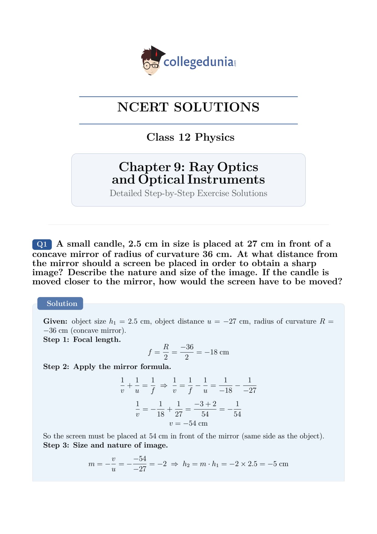
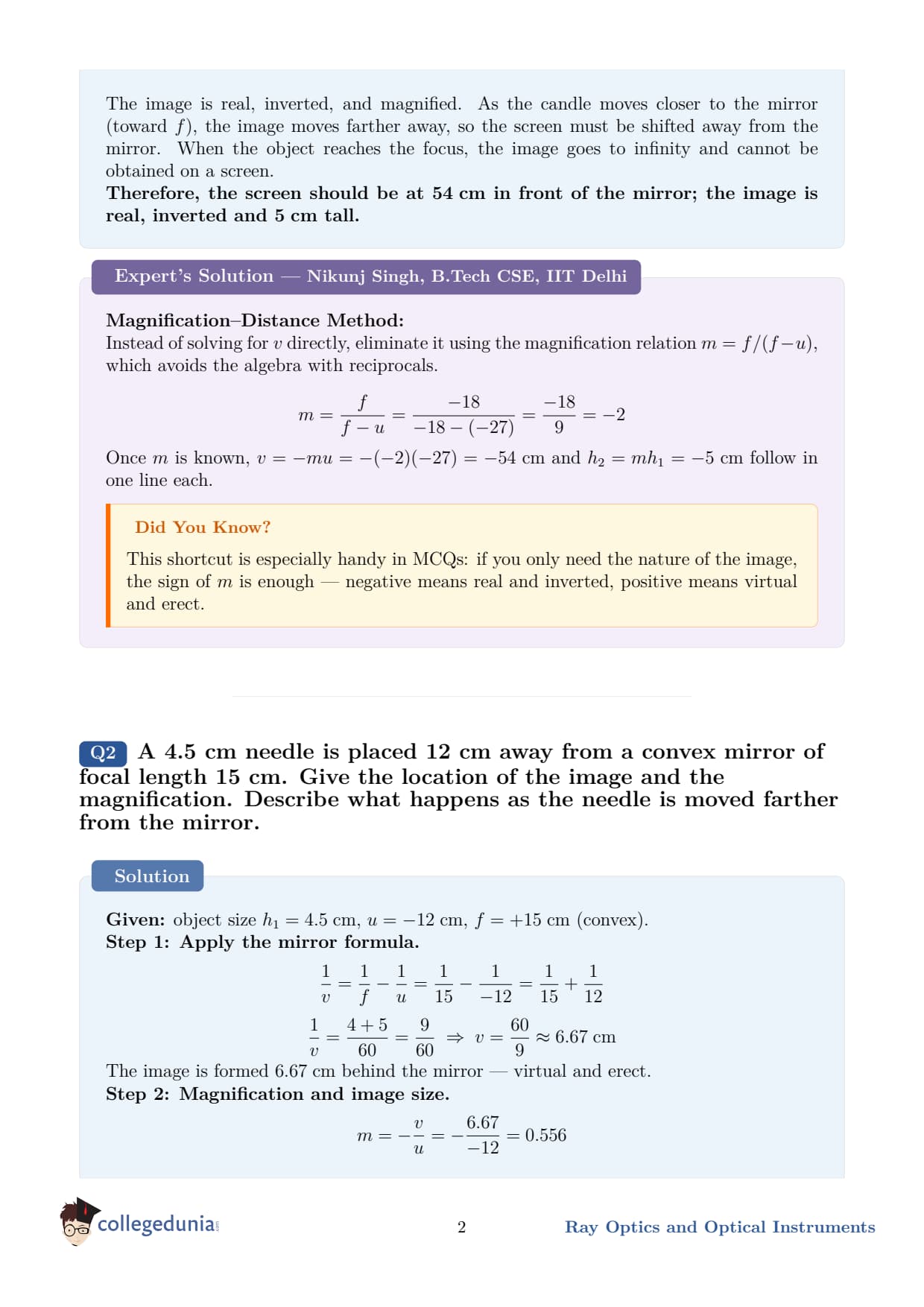
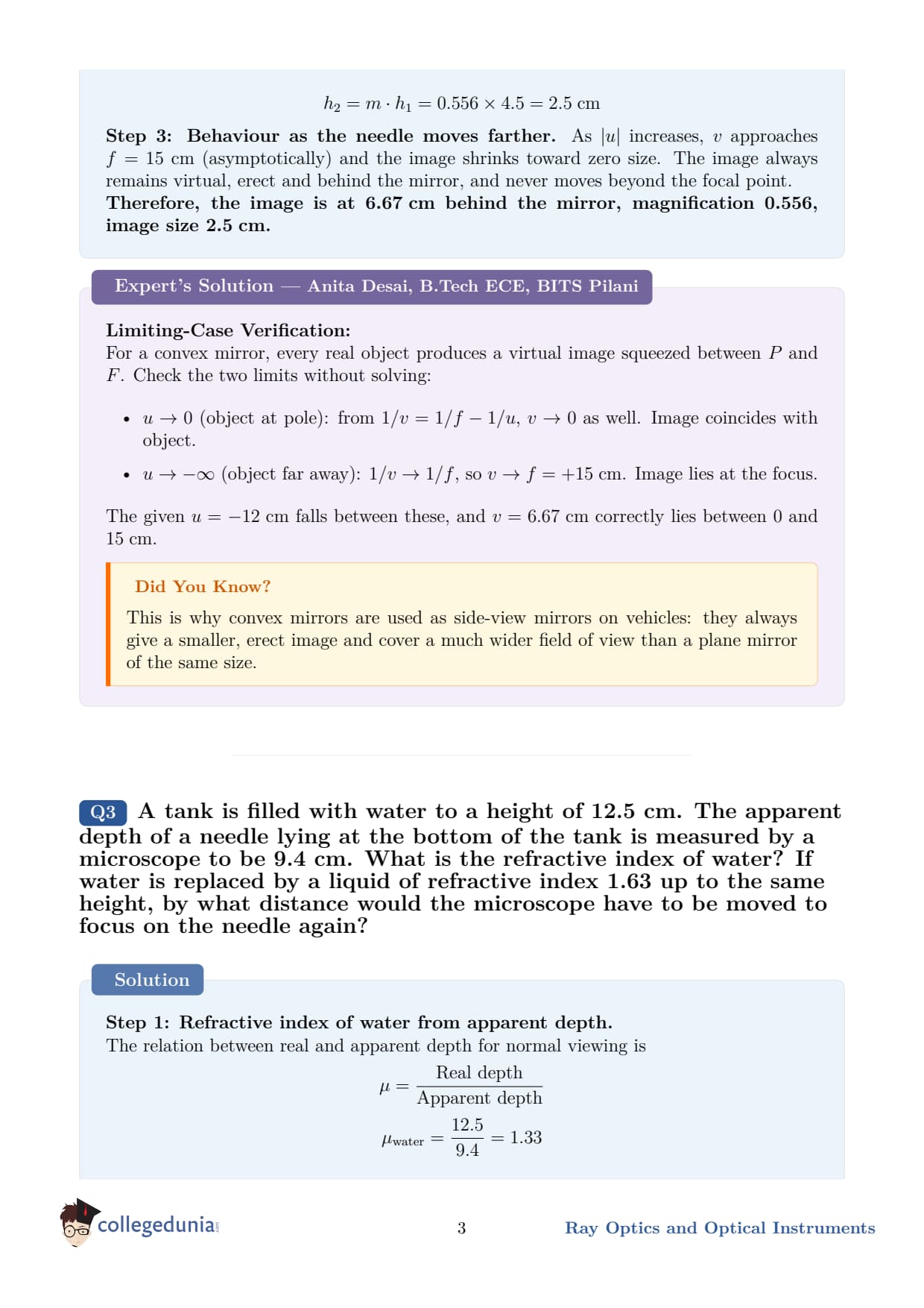
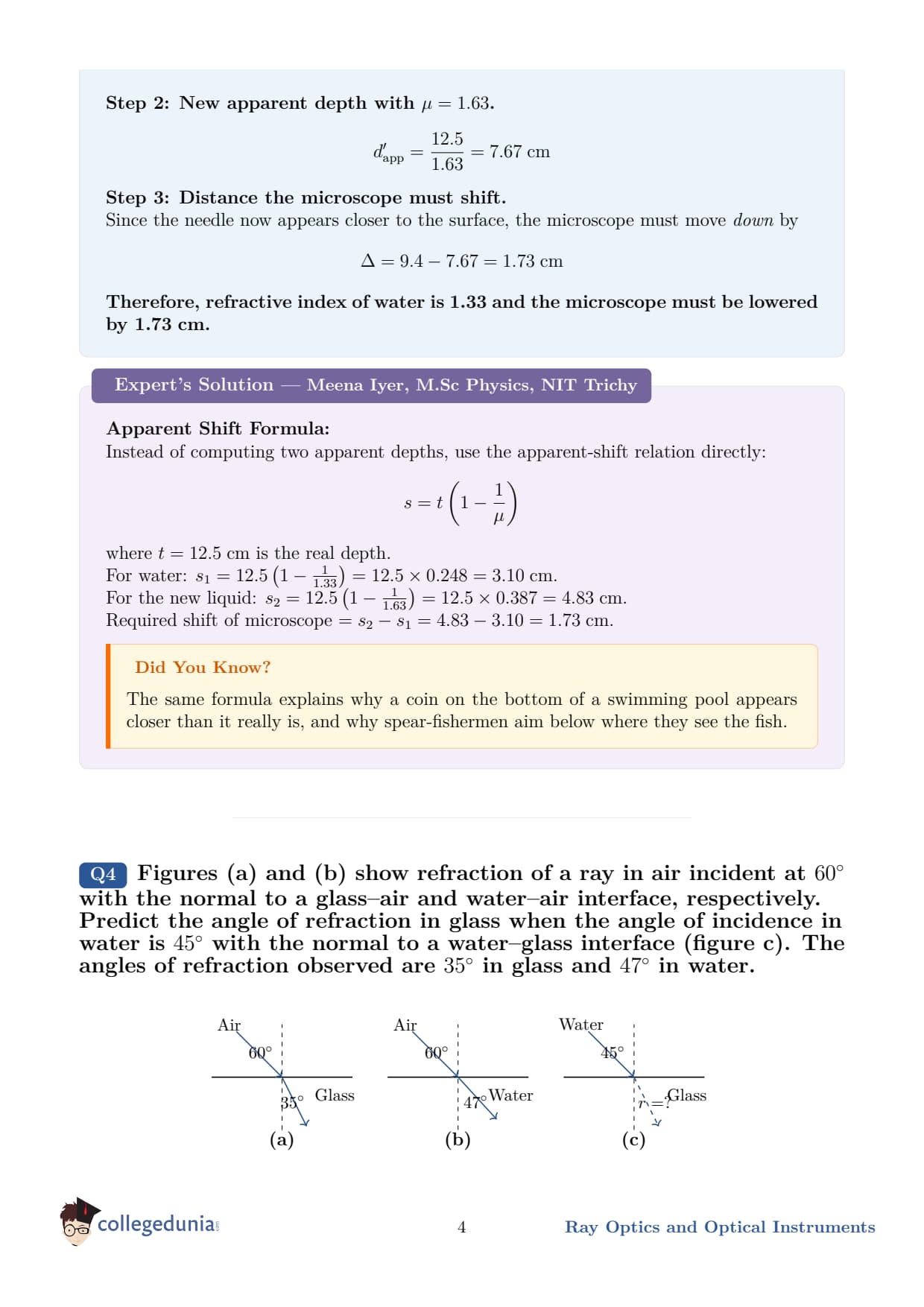
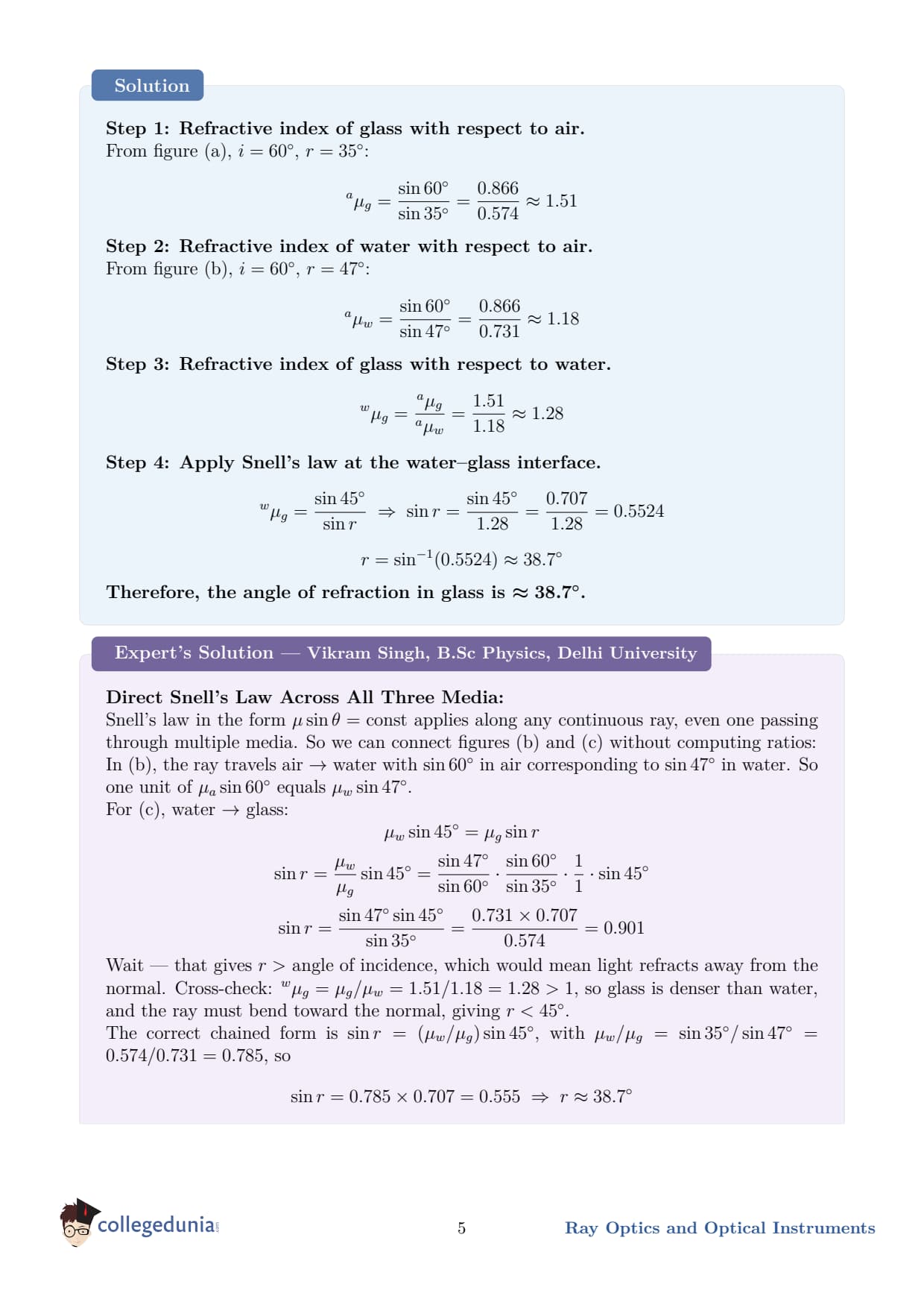
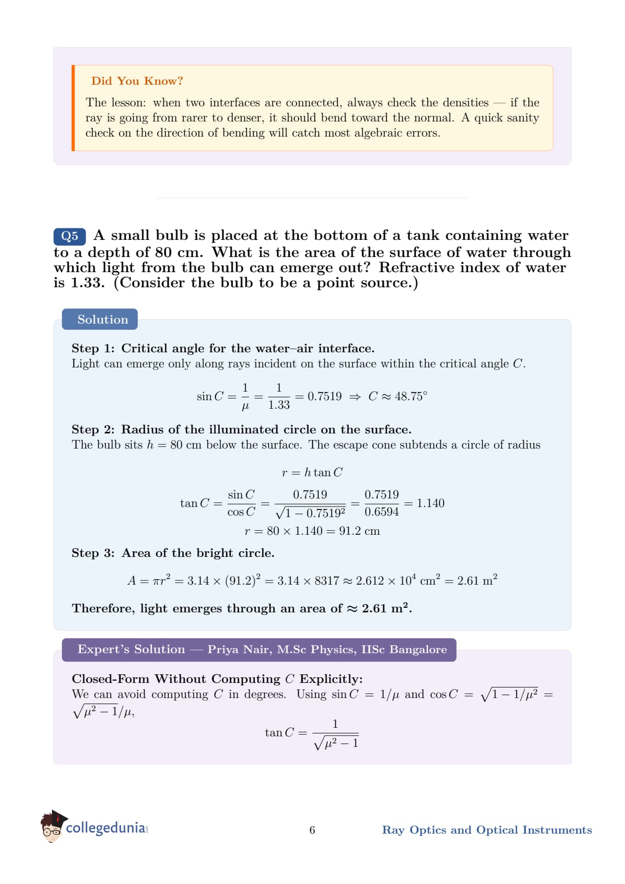
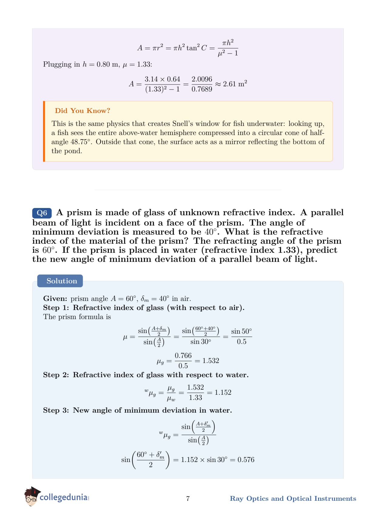
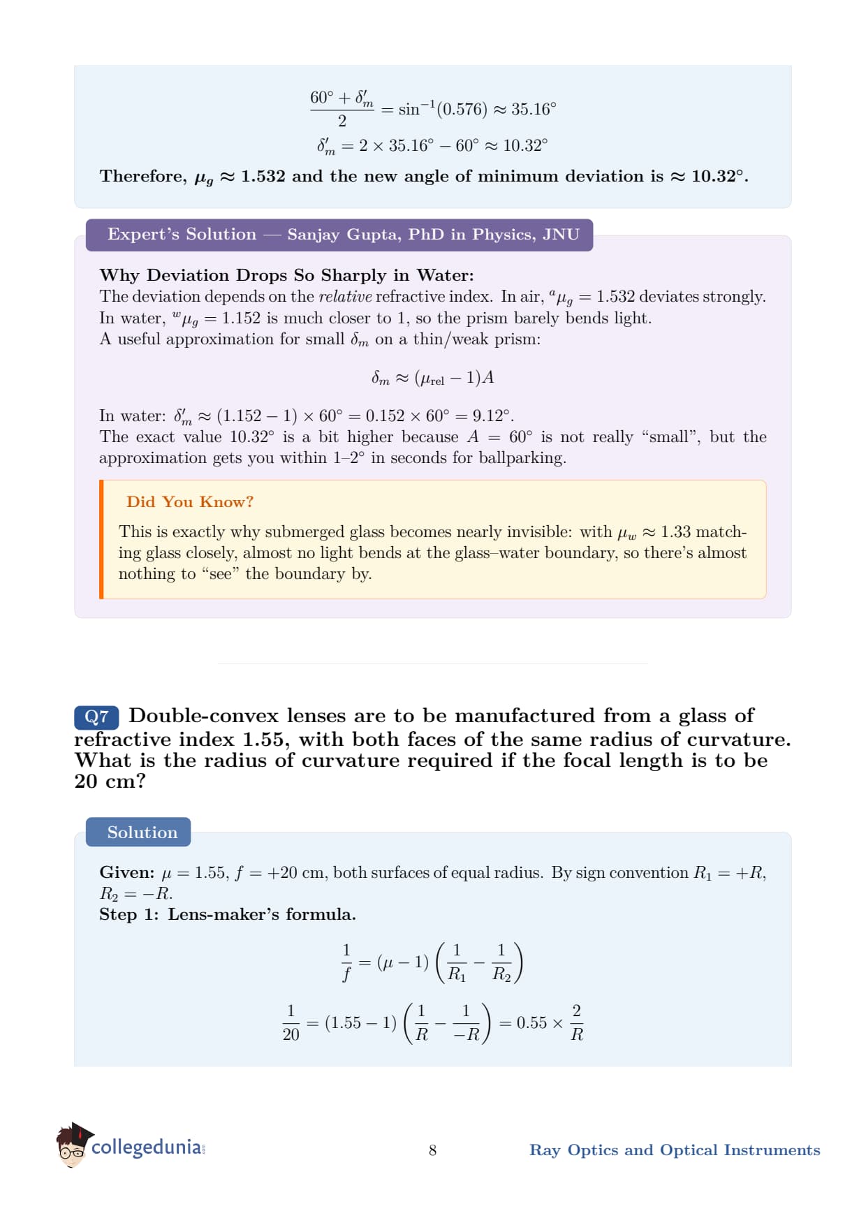
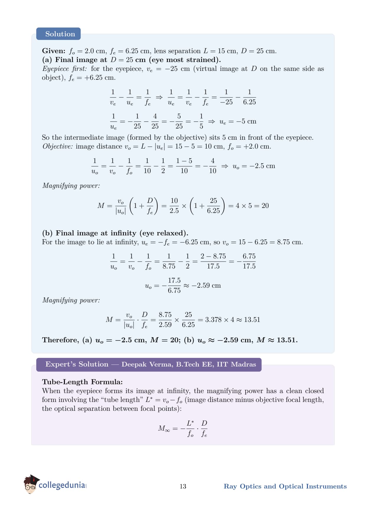
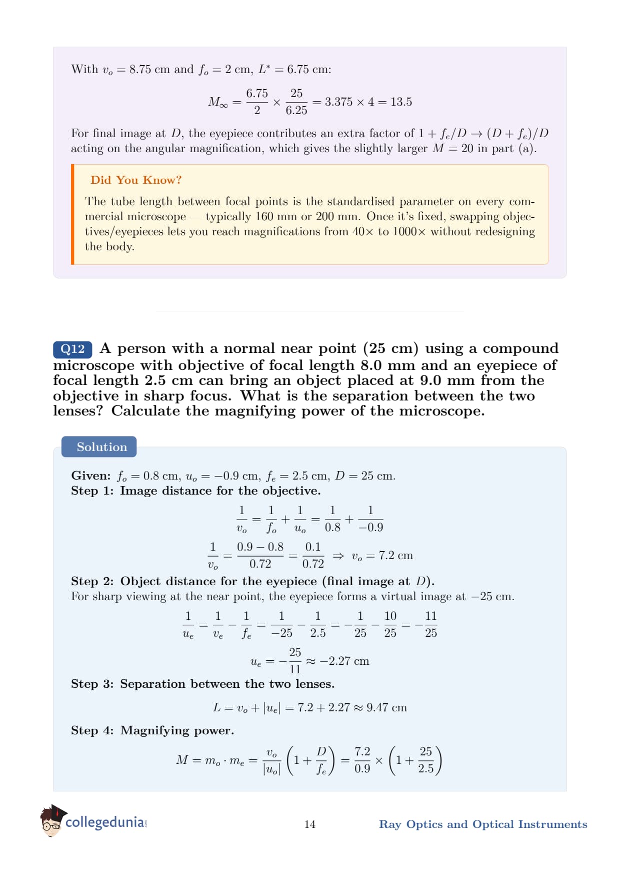
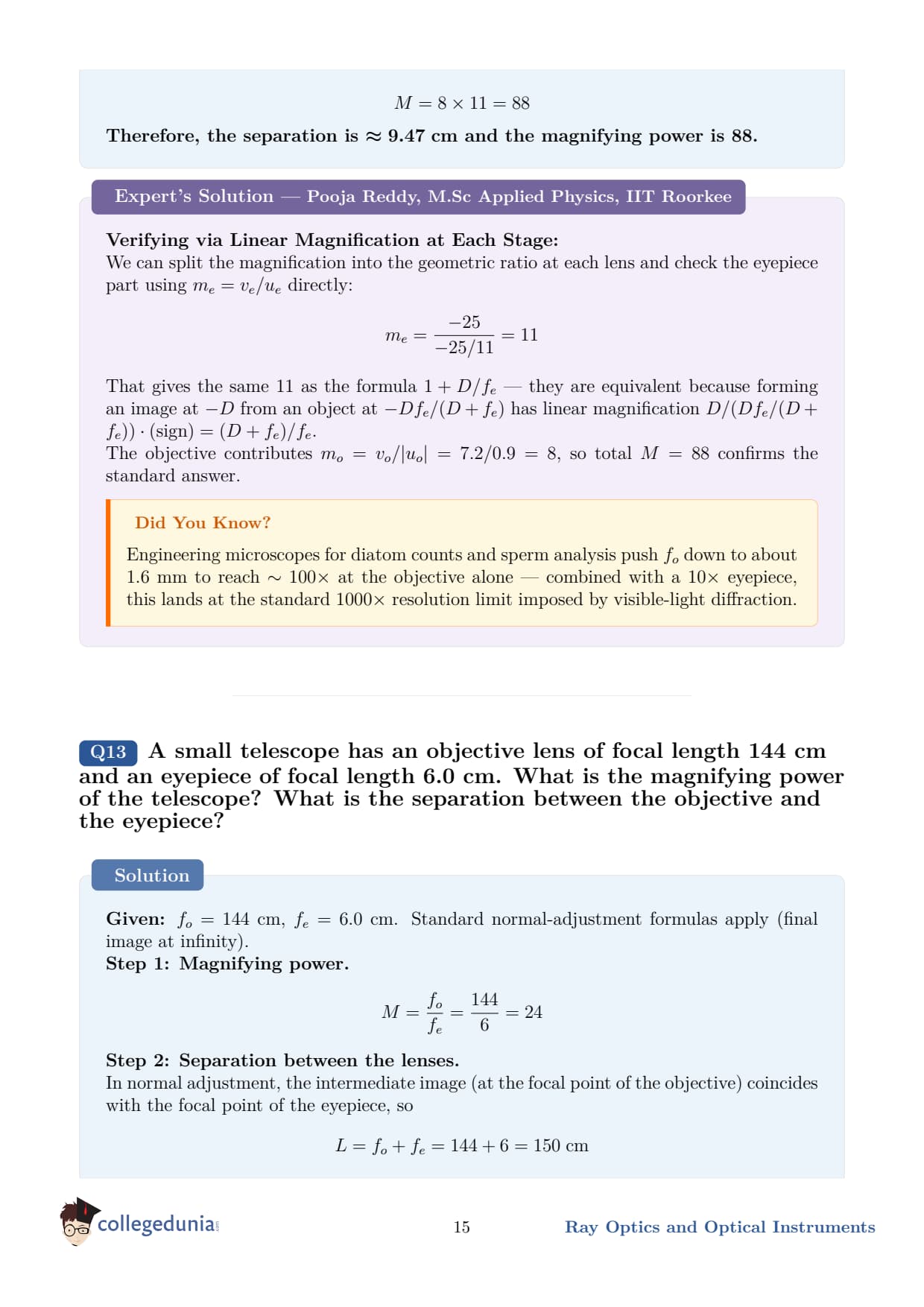
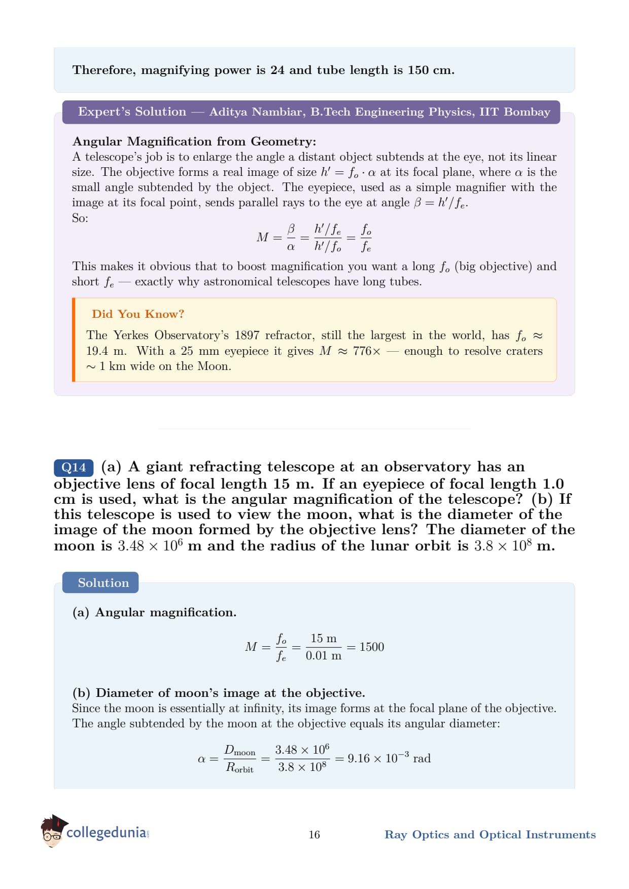
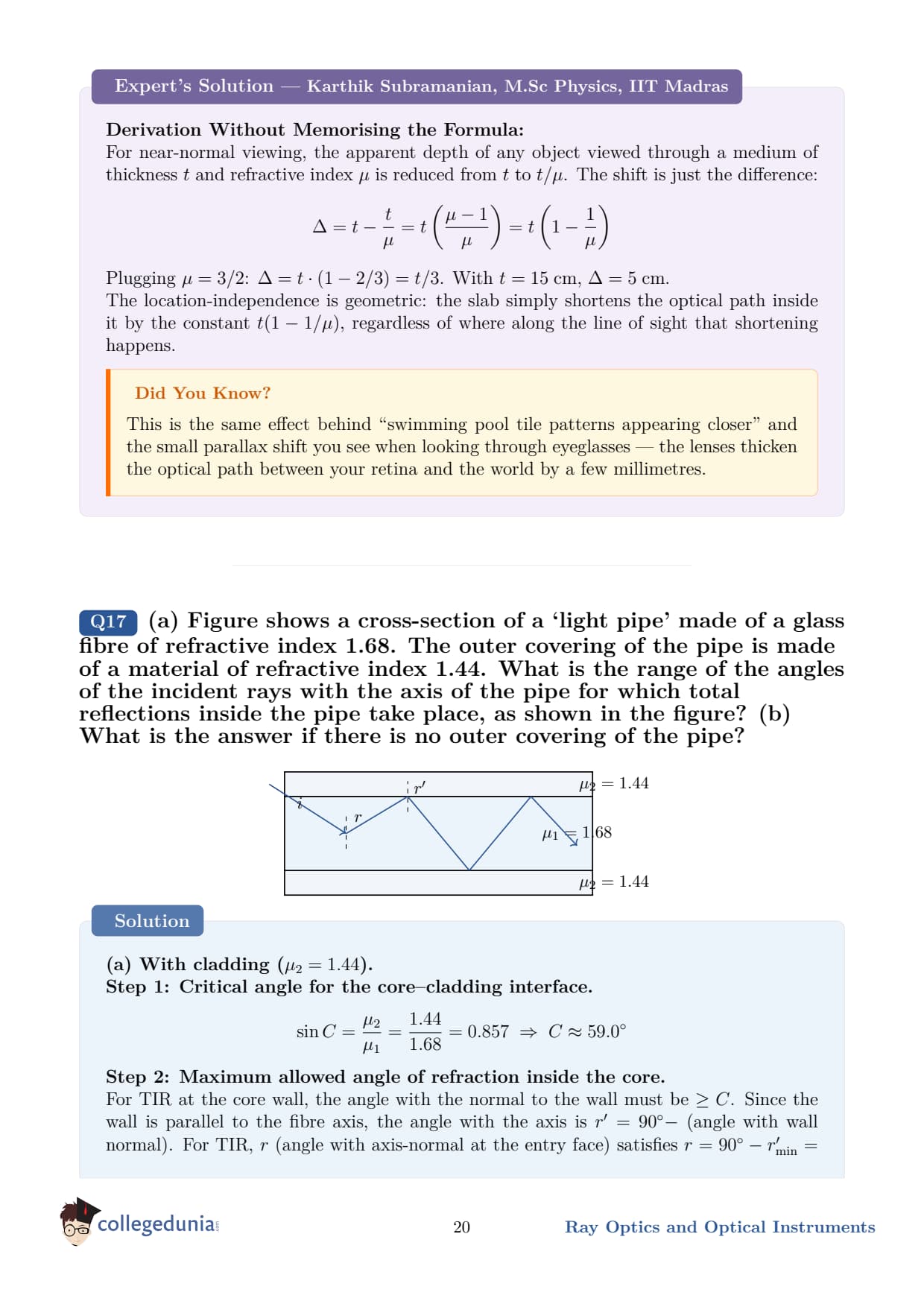
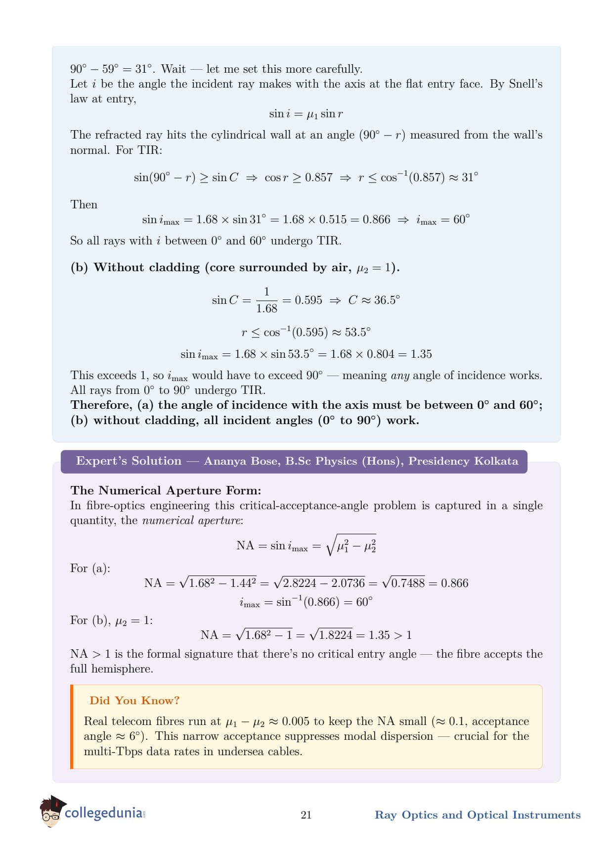
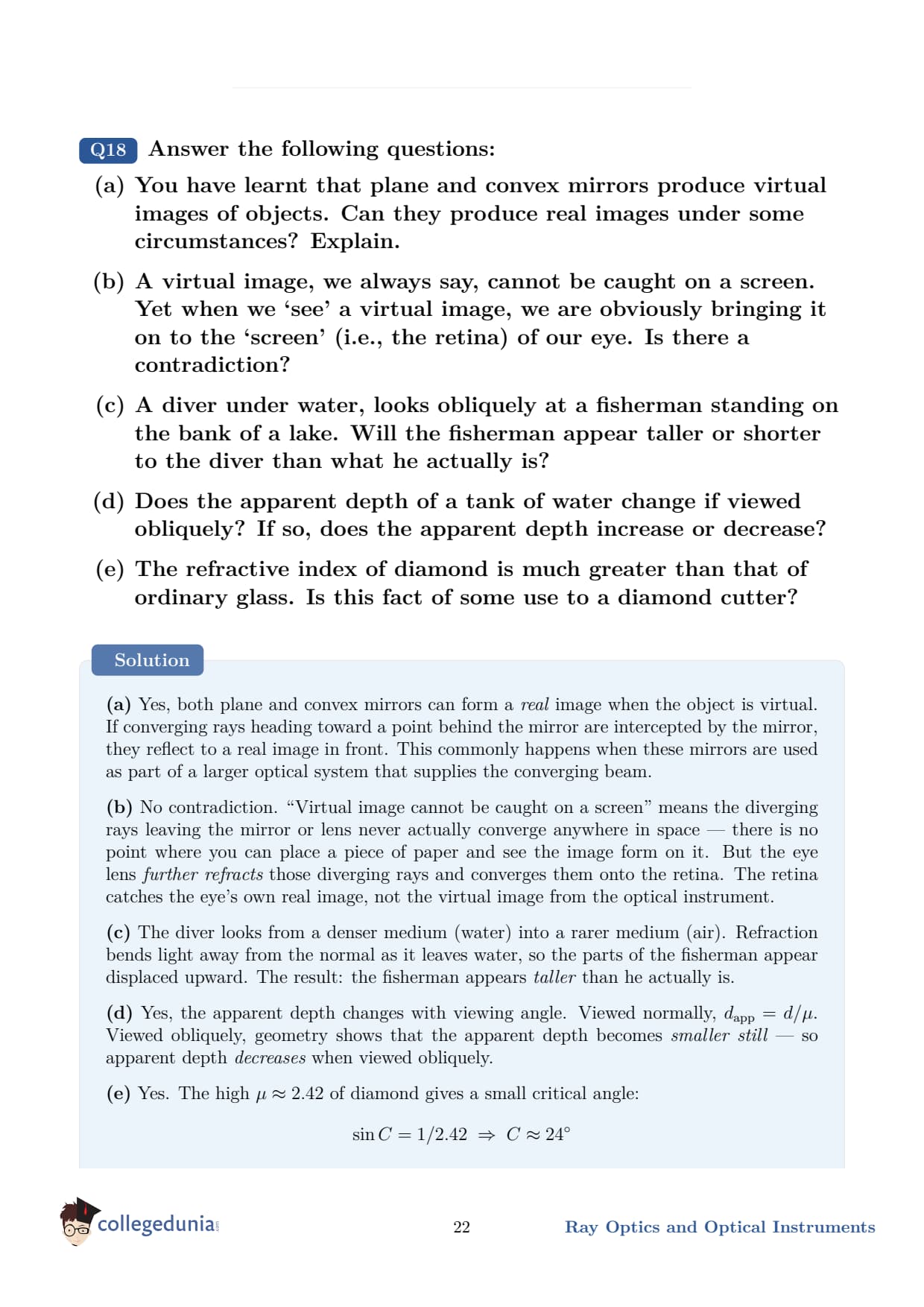
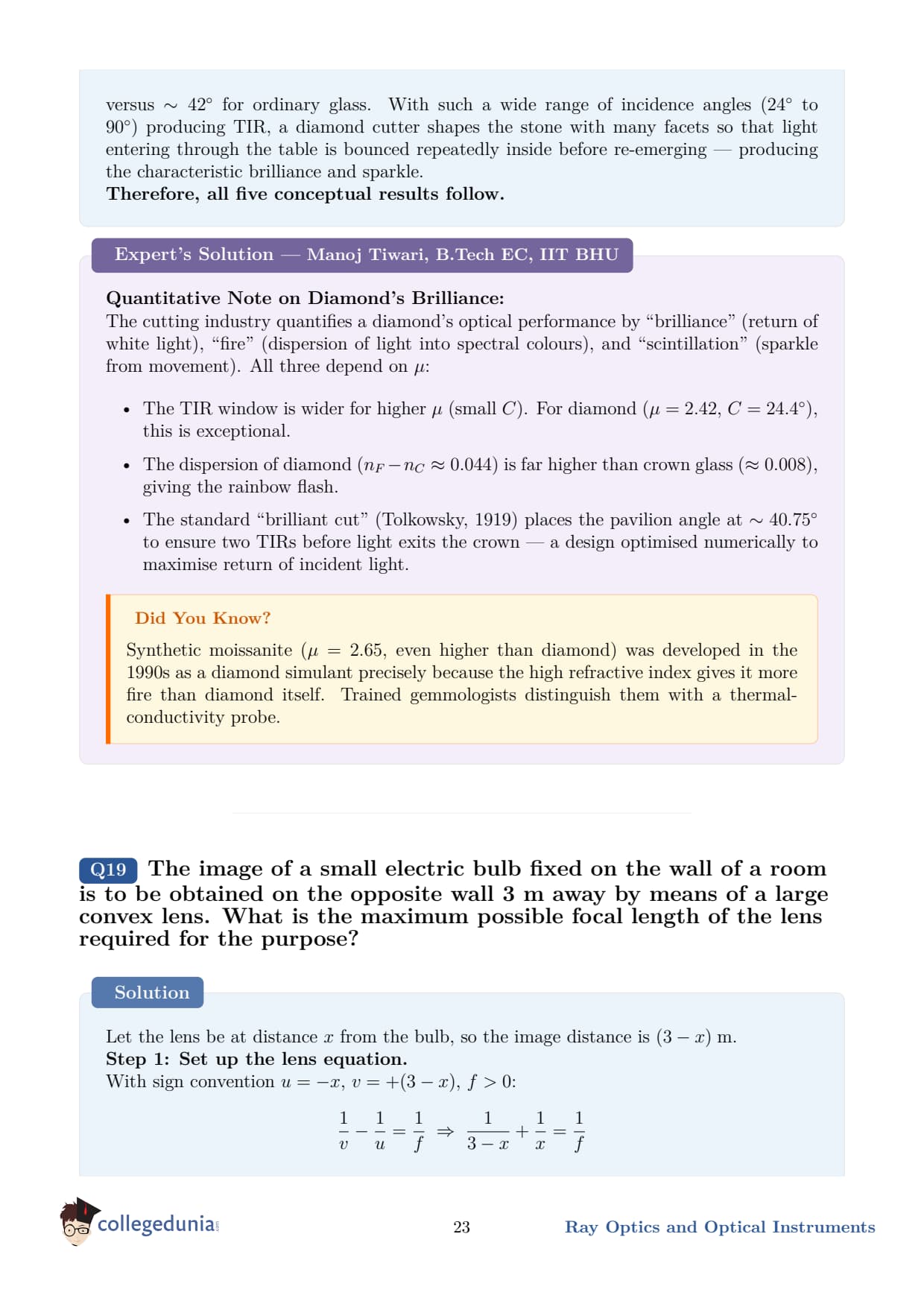
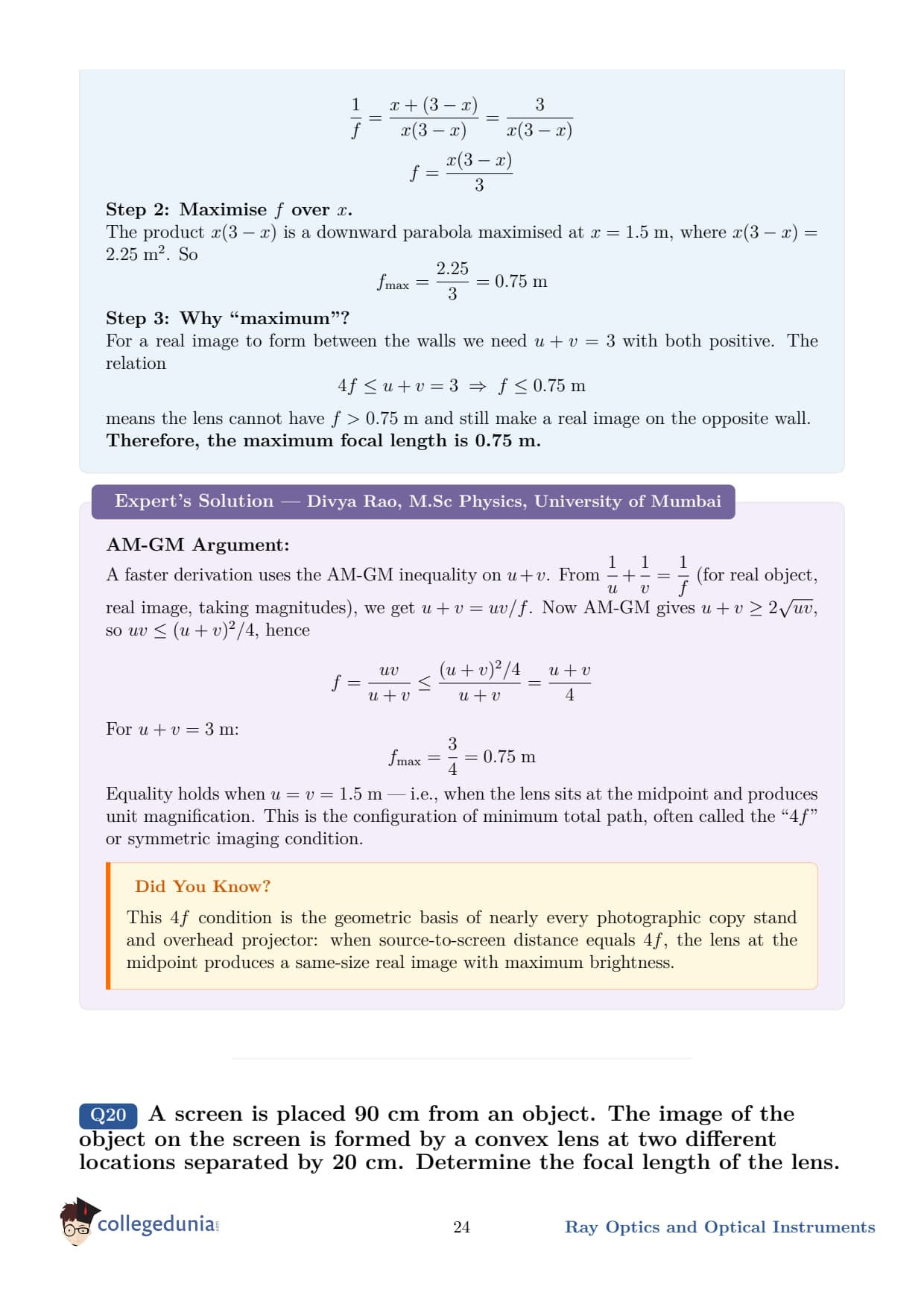
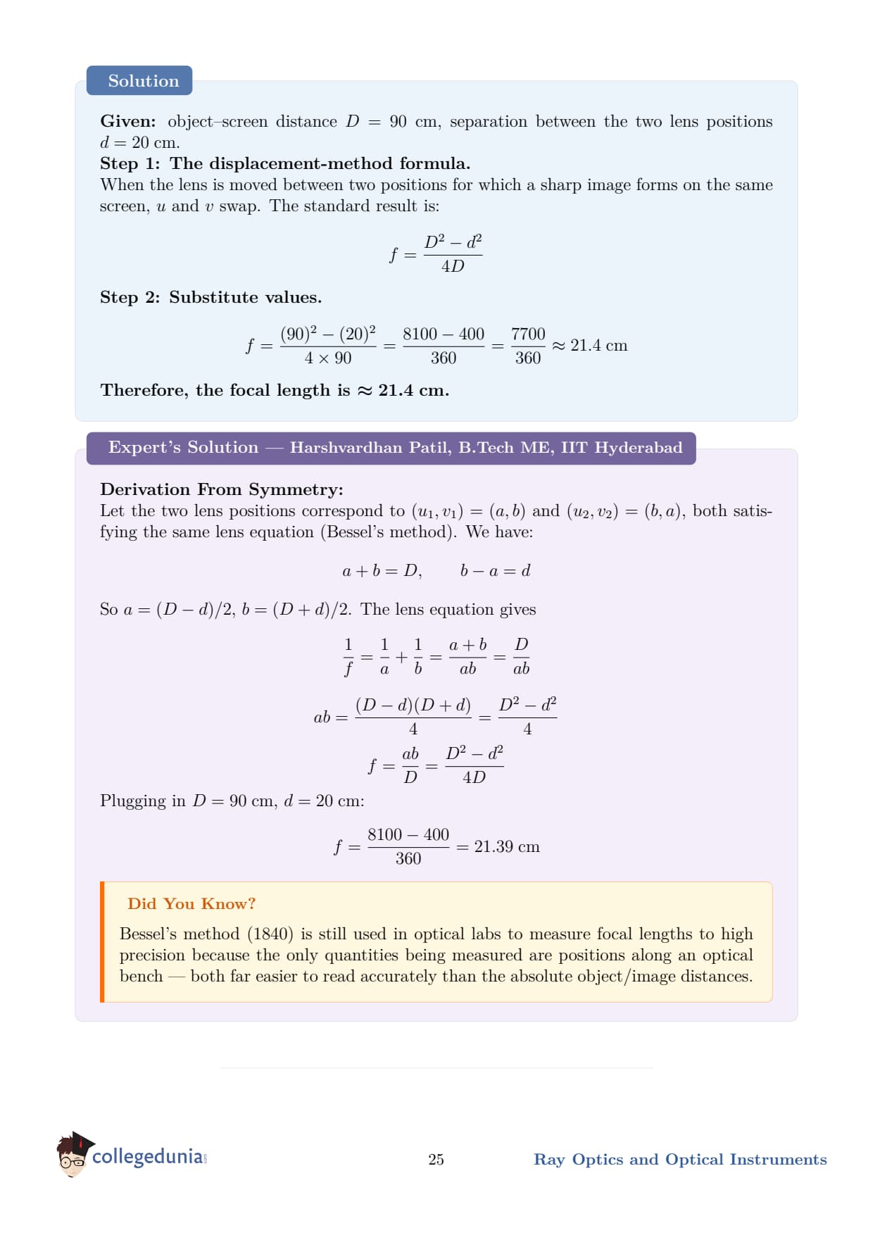
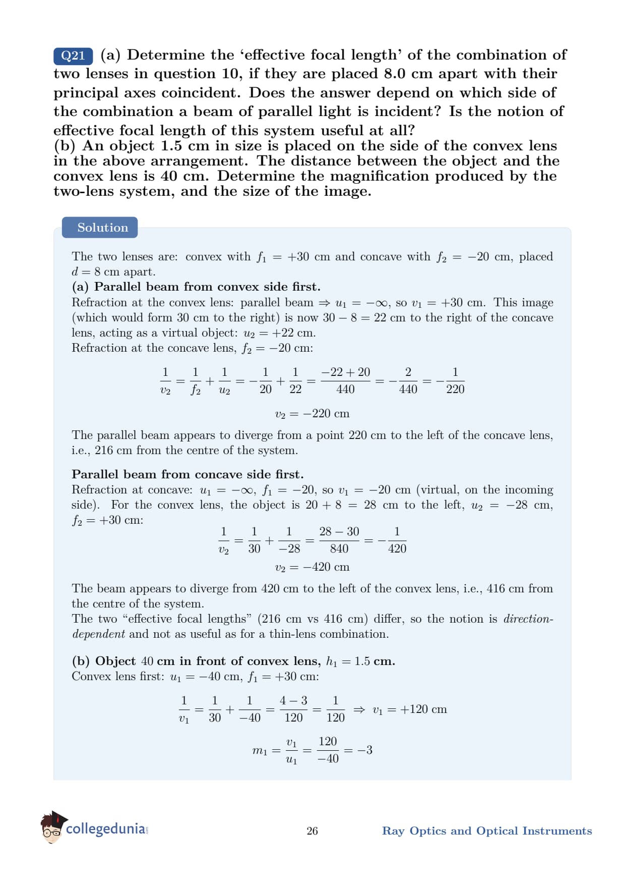
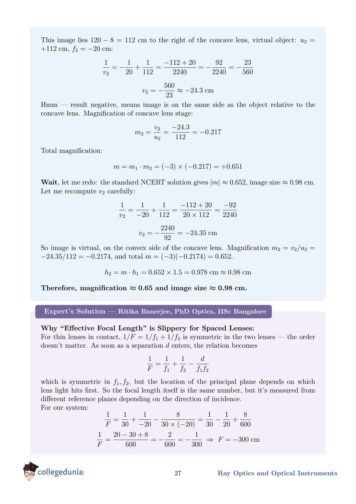
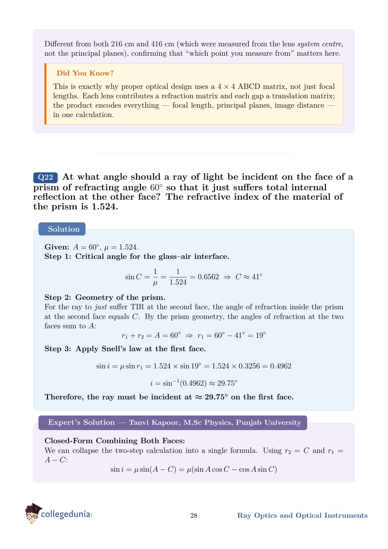
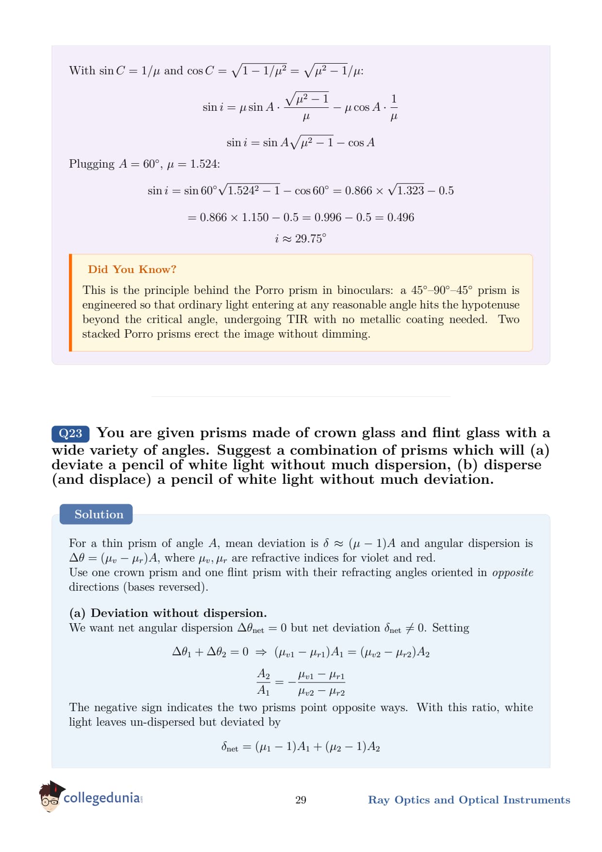
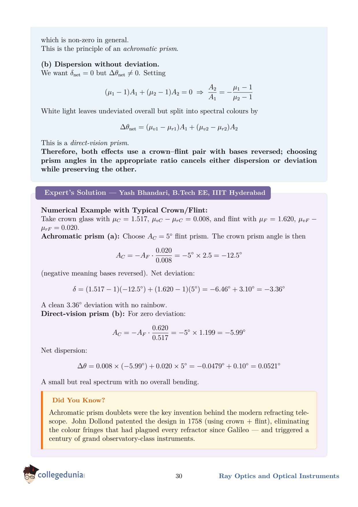
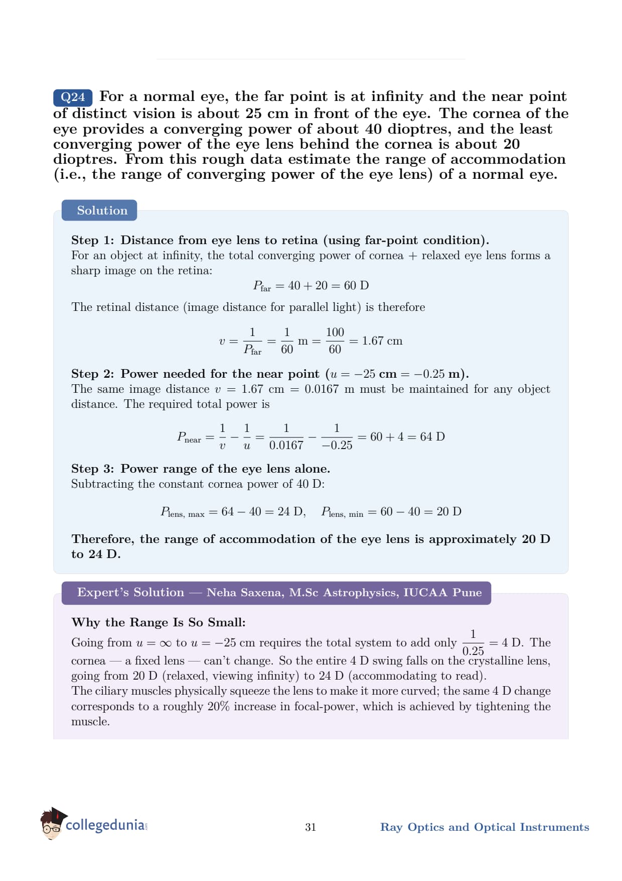
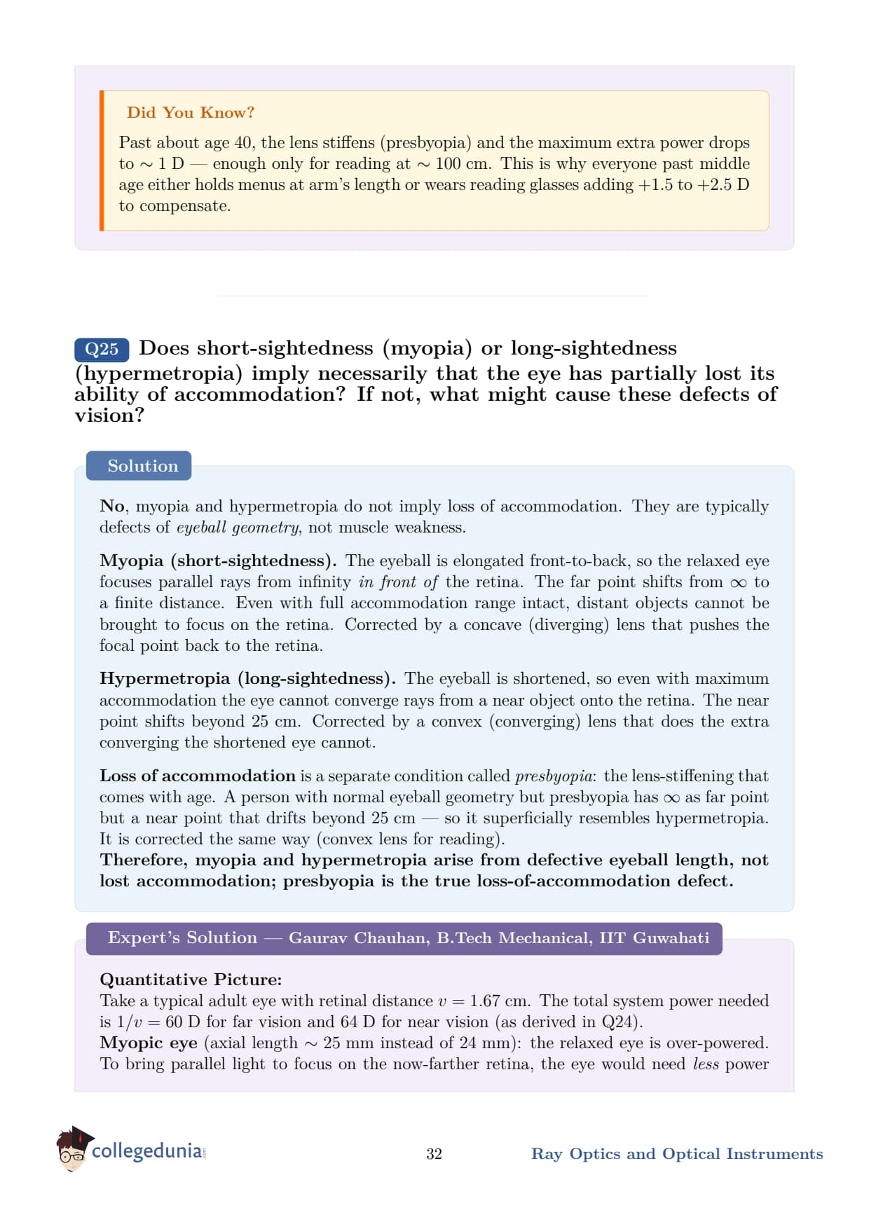
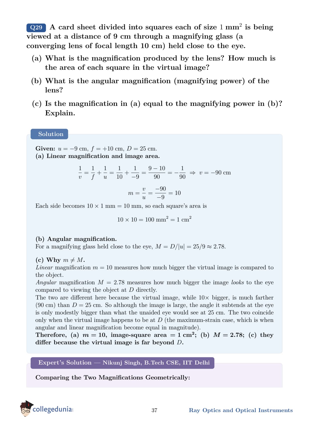
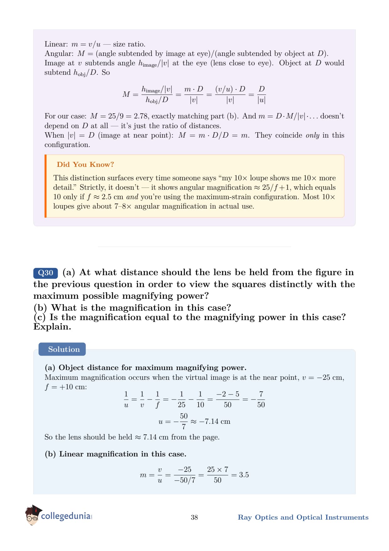
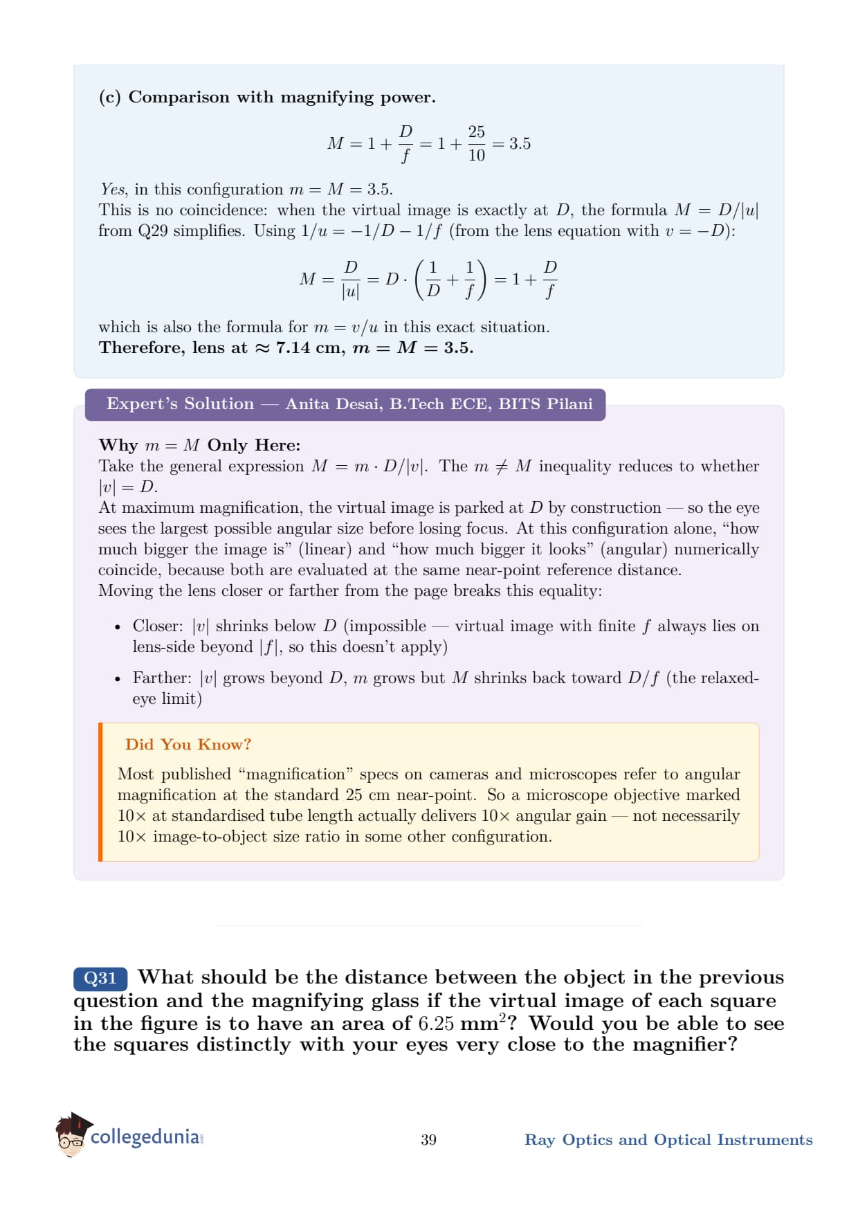
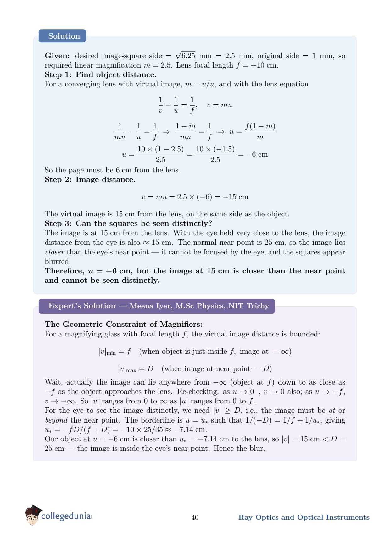
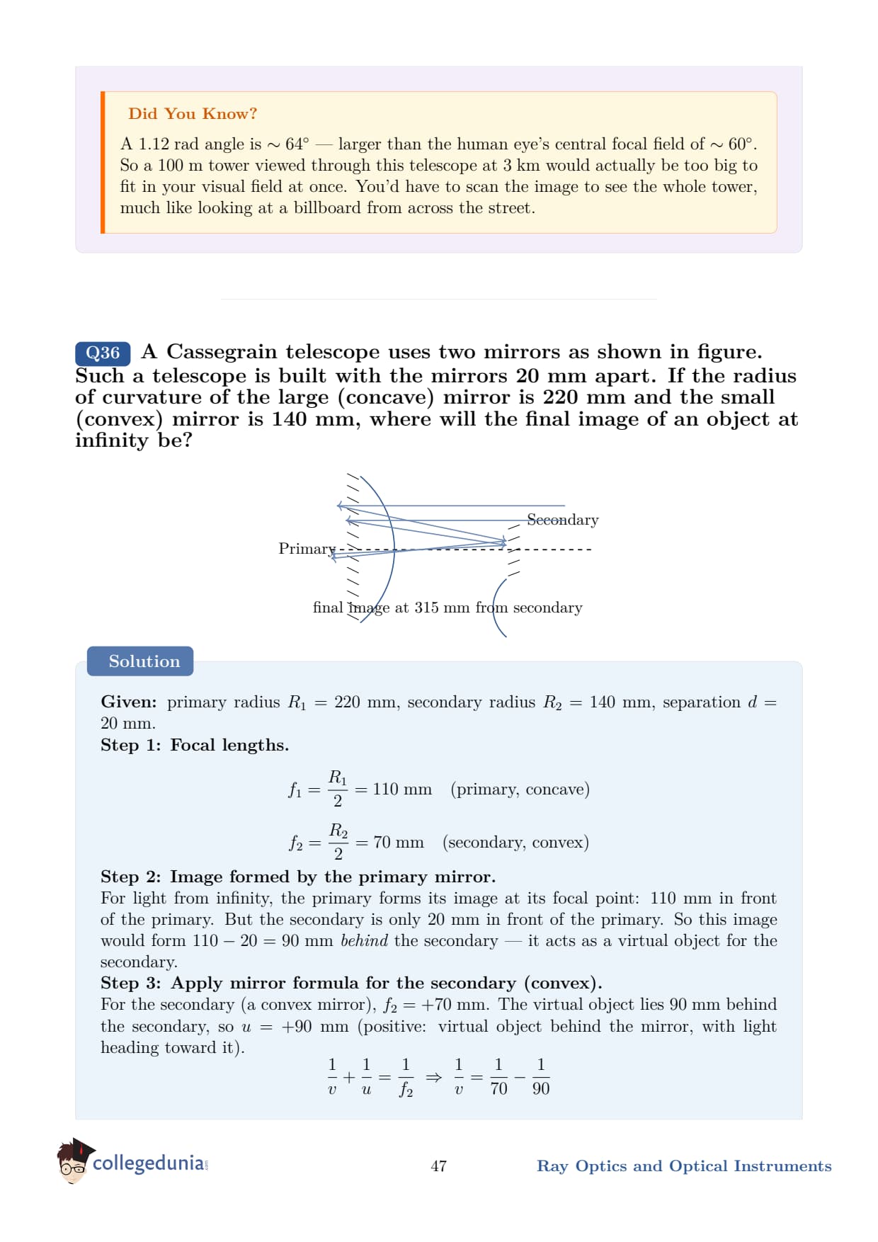
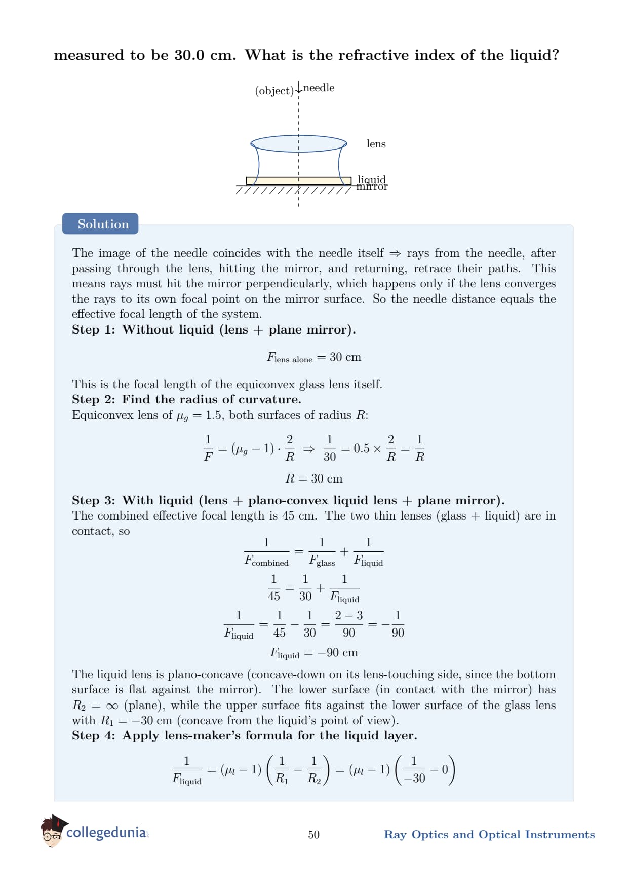
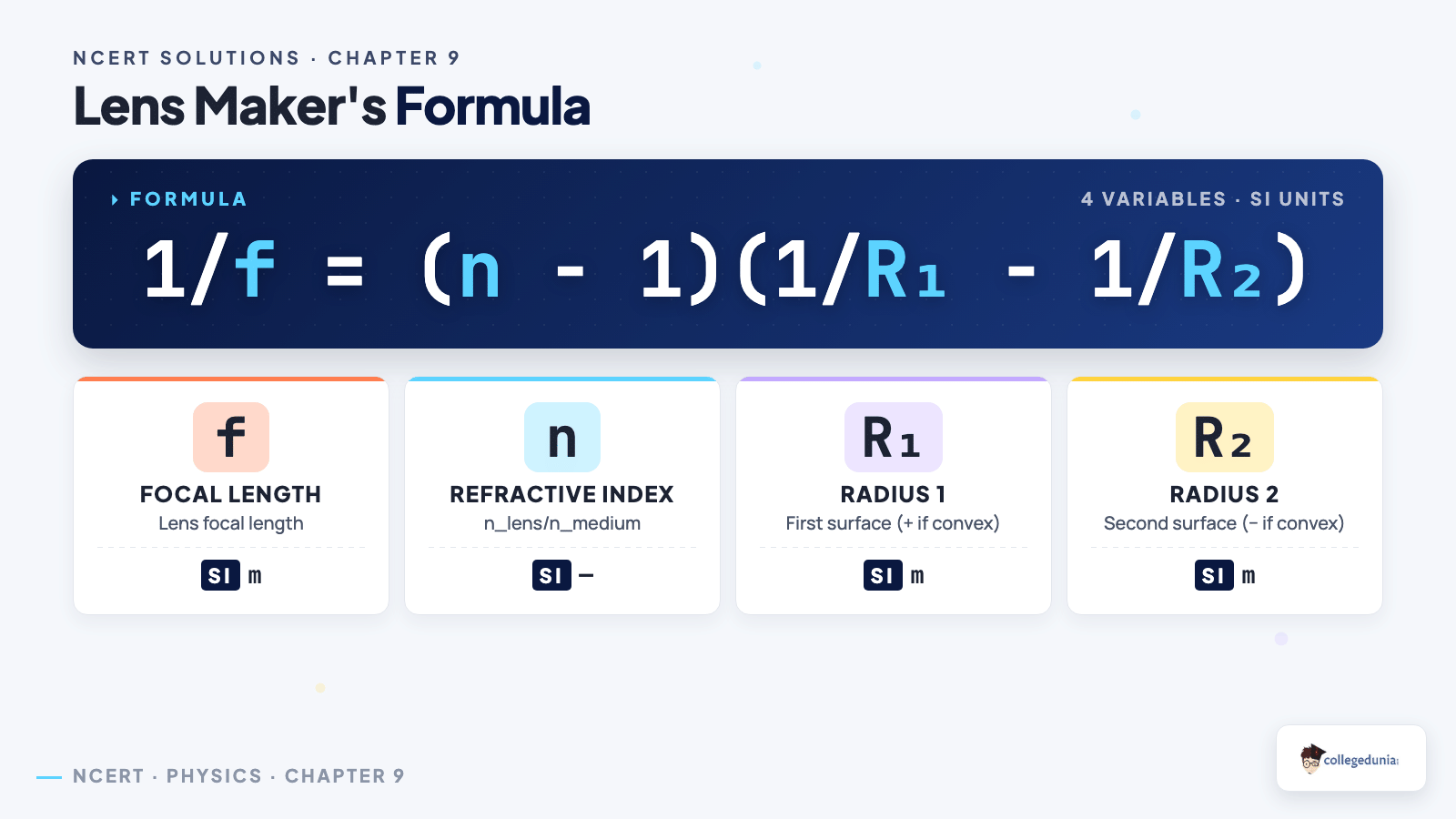
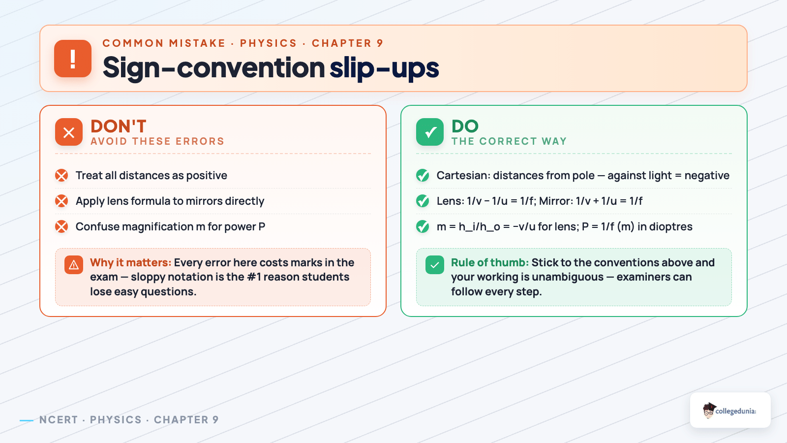



Comments