Physics Mentor, SRM Institute | Updated on - Jul 21, 2026
Electromagnetic Induction is worth about 5 marks in the CBSE Class 12 Physics board exam. It also shows up in JEE Main and NEET every year. This page hosts the free Chapter 6 NCERT Solutions PDF, the PYQ map, and a 12-formula revision list.
Here is what Chapter 6 is worth across the main exams:
CBSE Boards:5 marks, usually one 3-mark Faraday's law derivation plus one 2-mark numerical.
JEE Main: 3 to 4 percent, mostly Lenz's law direction and inductance numericals.
NEET: 1 to 2 questions a year on Faraday's law and eddy currents.
Every solution here is checked by subject experts and mapped to the 2026-27 NCERT.
How Will Collegedunia's NCERT Solutions for Class 12 Physics Chapter 6 Help You?
These solutions match the 2026-27 syllabus and mark every step for CBSE step-wise scoring. Each Lenz's law direction check is shown as a separate step.
2026-27 NCERT aligned: every back exercise solved; older deleted exercises are flagged but still solved for JEE and NEET practice.
Expert checked: clear flux diagrams, every formula verified against the official NCERT Part 2 print.
All NCERT Solutions for Class 12 Physics Chapter 6 Electromagnetic Induction with Step-by-Step Solutions
Every NCERT Class 12 Physics Electromagnetic Induction question is listed below. Click Check Solution for the step-by-step working and Expert Solution for the expanded explanation.
Q 6.1
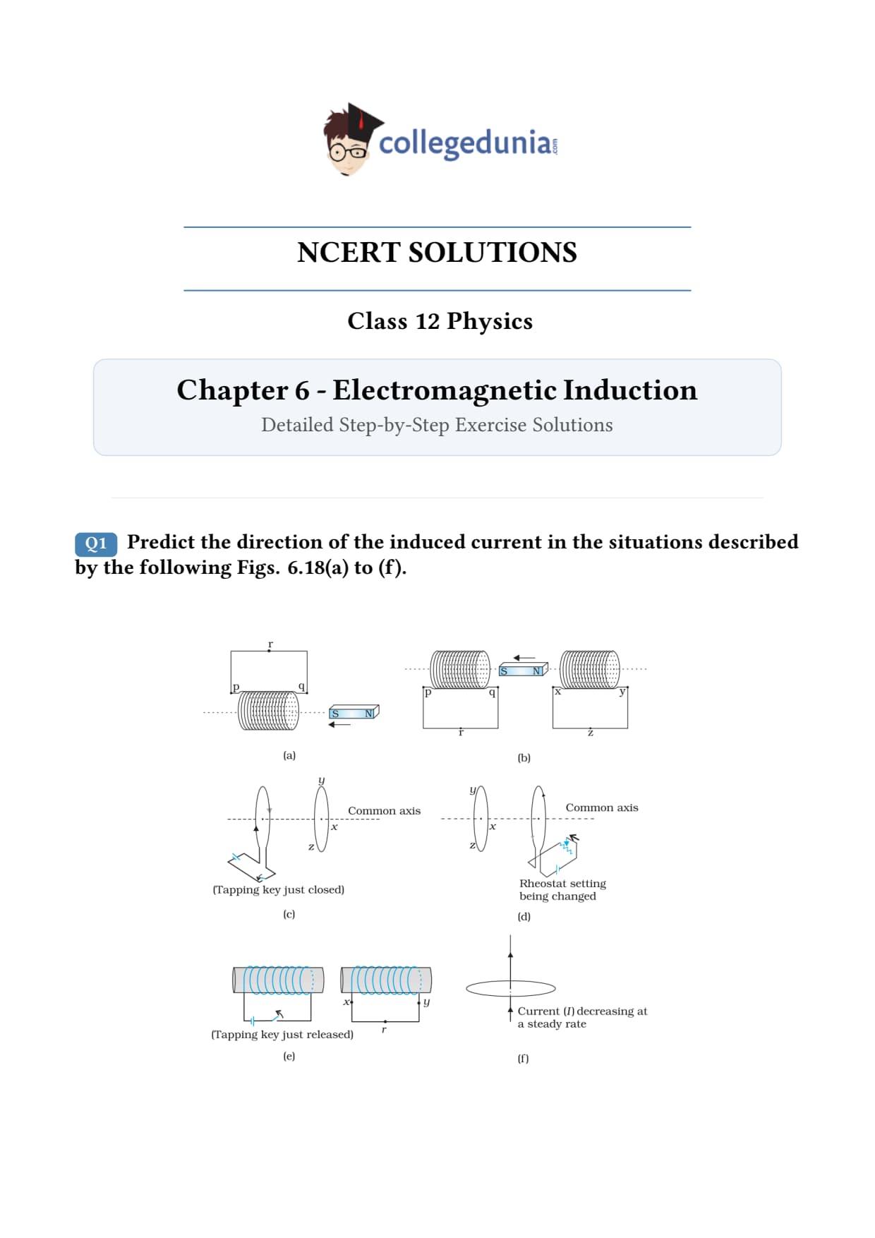
Predict the direction of induced current in the situations described by the following Figs. 6.15(a) to (f).
What the question is asking. Six different setups are shown in Fig. 6.15 of the textbook. In each, the magnetic flux through a coil/loop is changing - either because a magnet is moving, the loop is moving, or a current is changing in a neighbouring circuit. We must use Lenz's law to predict the direction of the induced current in each coil.
Concept used - Lenz's law. The induced current flows in such a direction that the magnetic flux it produces opposes the change in flux that caused it. In other words: the induced current tries to keep the flux through the loop the same as it was. Sign-wise this is captured by Faraday's law, ε = - dBdt. The minus sign is Lenz's law in mathematical form.
How to apply it (recipe).
Step A - figure out the direction of the existing magnetic flux through the loop (use right-hand rule for a bar magnet: outside the magnet, field lines run from N → S).
Step B - decide whether that flux is increasing or decreasing.
Step C - the induced current must create a flux that opposes the change. If flux is increasing, induced current creates flux in the opposite direction; if decreasing, the induced current creates flux in the same direction (to compensate).
Step D - apply the right-hand rule to the loop to get the direction of the current that produces this opposing flux.
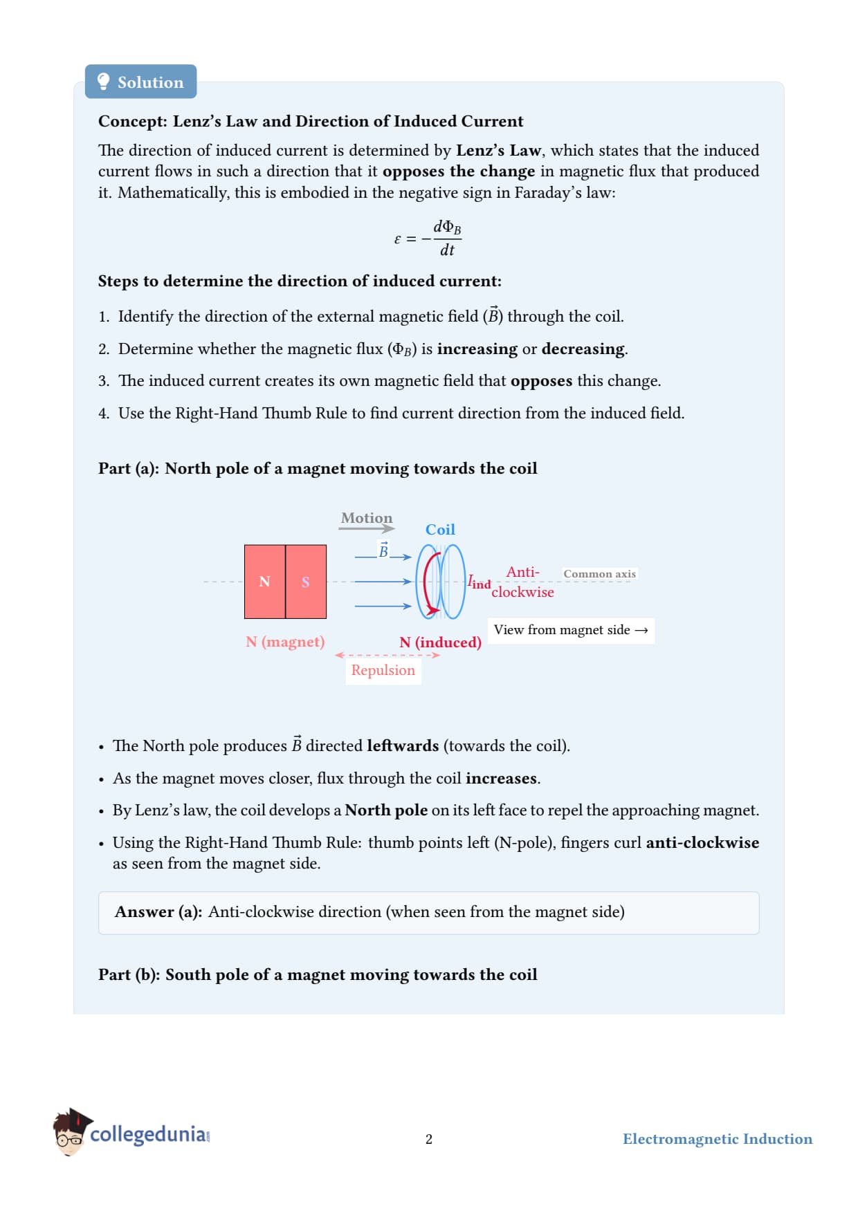
Step 1 - Fig. 6.15(a). A bar magnet's N-pole is brought near a closed loop (pcd, in the plane). Flux into the loop on the side facing the N-pole increases. To oppose this, the induced current must create flux out of that face - by right-hand rule, the current flows anticlockwise as seen from the magnet's side. Hence the induced current direction is along the path qrpq.
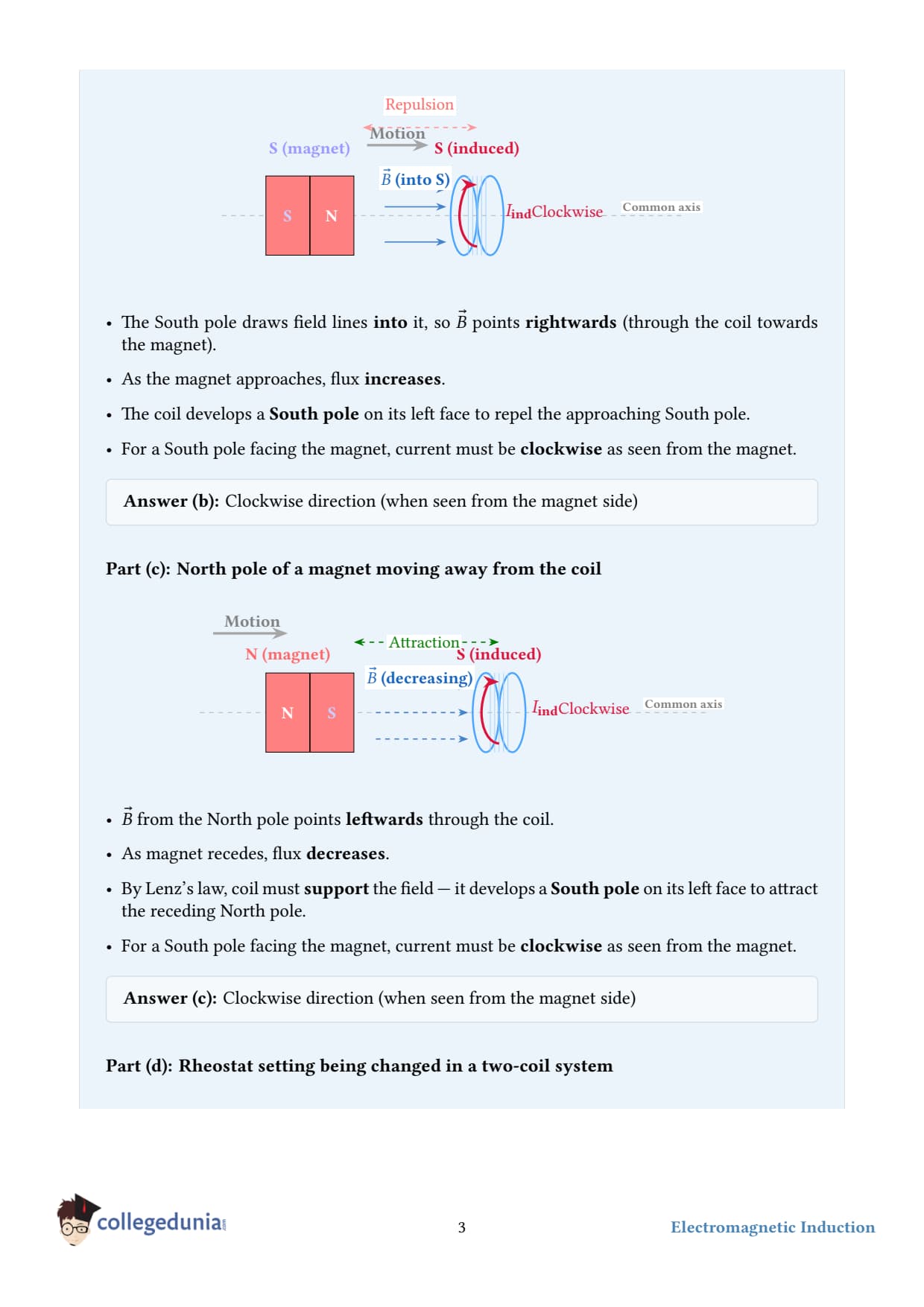
Step 2 - Fig. 6.15(b). Two loops: one has a magnet moving away from it. Flux through that loop is decreasing. The induced current in the second loop must support the dying flux - direction prq in the first loop and yzx in the second.
Step 3 - Fig. 6.15(c). A current is suddenly switched on in a coil (left). Flux through the right coil grows from zero. Induced current opposes the increase - flows yzx.
Step 4 - Fig. 6.15(d). The right coil is moved towards the left coil (which carries a steady current). Flux through the right coil increases. Induced current opposes - direction zyx.
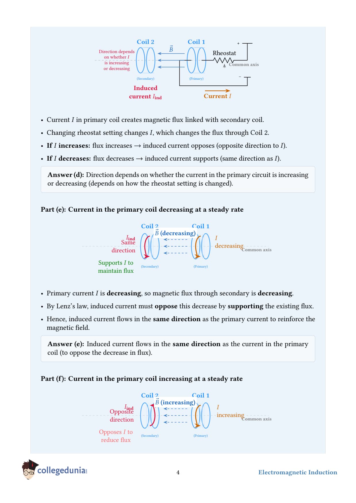
Step 5 - Fig. 6.15(e). The iron rod is removed from the solenoid (or current in the primary is broken). Flux through the secondary drops. Induced current opposes the drop - flows in the direction that maintains the original flux: xry.
Step 6 - Fig. 6.15(f). The current-carrying wire is in the plane of the loop. Field lines from the wire lie in the plane of the loop, so the net flux through the loop is zero and does not change. Hence no induced current.
Final answer.
(a) qrpq
(b) prq and yzx
(c) yzx
(d) zyx
(e) xry
(f) no induced current (flux is zero and unchanging)
DR
Dr. Rajesh Kumar
Ph.D. Physics, IIT Delhi
Verified Expert
Why Lenz's law has to be true - energy conservation. Imagine if the induced current supported the change instead of opposing it. Pushing a magnet towards a coil would create a current that pulled the magnet in faster - which would grow the current more - which would pull harder still, building unlimited kinetic energy from nowhere. That violates energy conservation. The minus sign in Faraday's law is nature's way of saying "no free lunch": you must do work against the induced force to drive the change.
Right-hand rule for loop current → flux. Curl the fingers of your right hand along the direction of current flow in the loop; the thumb points in the direction of the magnetic field produced inside the loop. This is the workhorse rule for translating "I need flux pointing this way" into "current must flow this way."
Common mistake. Students sometimes apply Lenz's law to the field of the magnet instead of the loop. Lenz's law speaks only about the flux through the loop and the field produced by the induced current - never about the magnet's own field. Always ask: "How is the flux through the loop changing, and what current would oppose that change?"
Real-world example - induction cooktops. A copper coil under the ceramic surface carries an alternating current at ~25 kHz, producing rapidly changing magnetic flux. The iron base of the pan acts as the second coil - induced eddy currents heat it (Joule heating). The cooktop itself stays cool because ceramic is non-magnetic. This is Lenz's law put to work: the induced current heats the metal of the pot, not the air around it.
Q 6.2
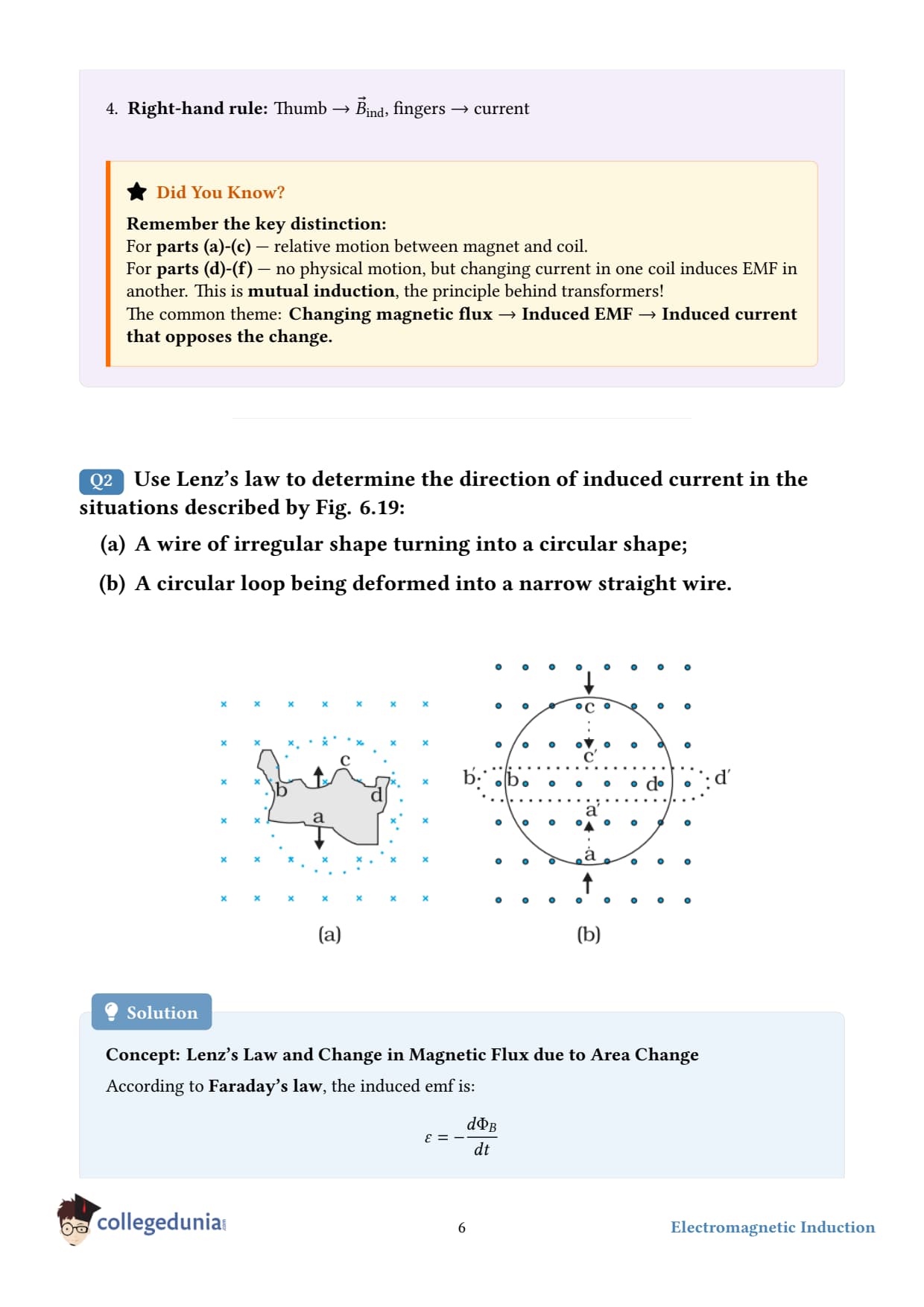
Use Lenz's law to determine the direction of induced current in the situations described by Fig. 6.16:
(a) A wire of irregular shape turning into a circular shape;
(b) A circular loop being deformed into a narrow straight wire.
Concept used - Lenz's law. The induced current flows so as to oppose the change in magnetic flux through the loop. To apply it we need to ask: is the area of the loop increasing or decreasing? Since the magnetic field is given to be uniform and perpendicular to the plane of the loop (out of the page, in the figure), the flux is simply B = BA. With B fixed, any change in flux comes from a change in area A.
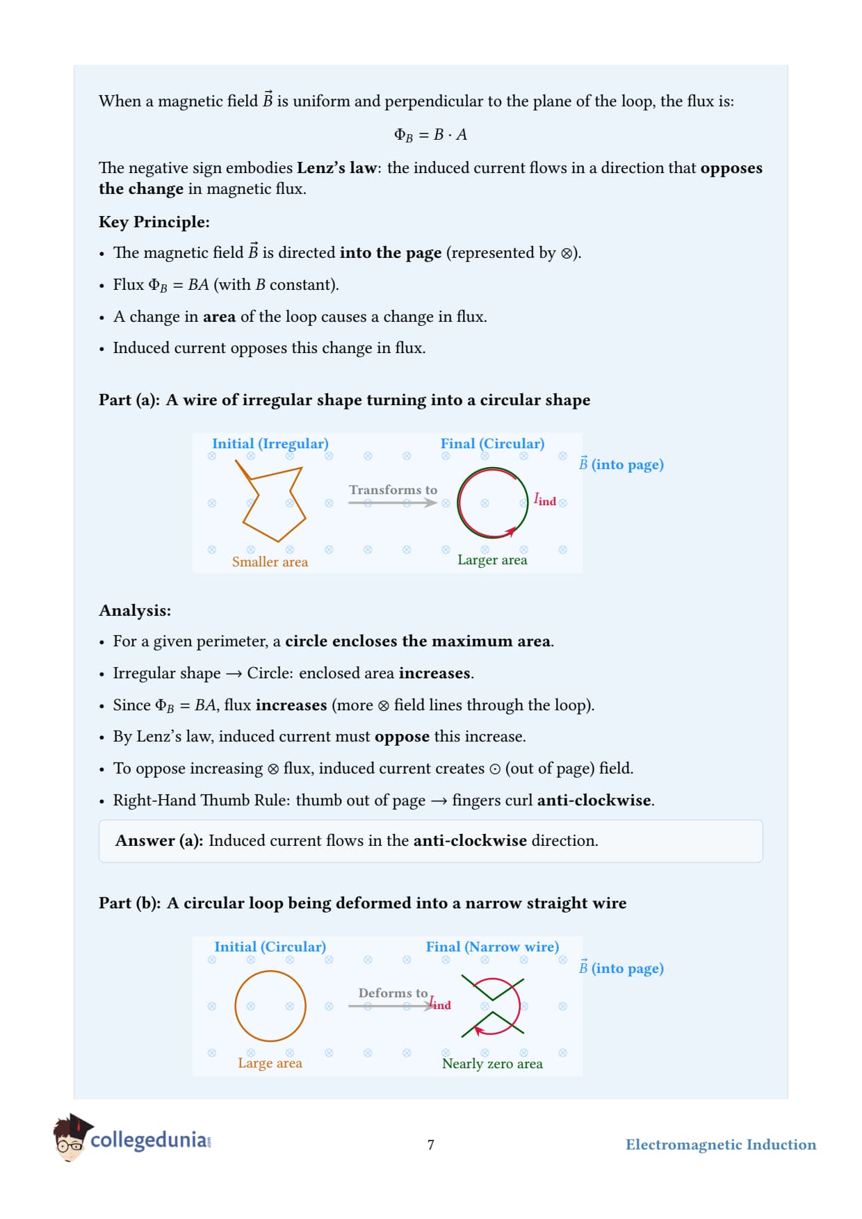
(a) Irregular shape → circular shape.
Step 1 - area change. For a fixed perimeter (length of wire), the circle is the shape with the maximum area (a classical isoperimetric result). So as the irregular loop morphs into a circle, the enclosed area increases.
Step 2 - flux change. With B out of the page (say) and A increasing, the flux Φ = BA is increasing in the out-of-page direction.
Step 3 - apply Lenz's law. The induced current must produce a flux into the page (to oppose the increase). By right-hand rule, that requires the current to flow clockwise as seen from the front (i.e., looking at the page) - direction a→ d→ c→ b→ a in the figure's labelling.
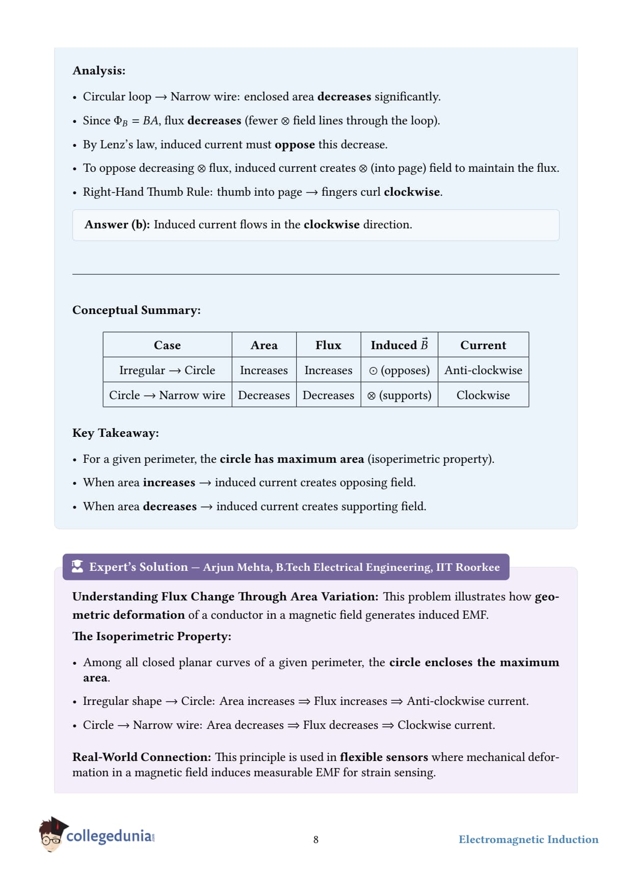
(b) Circular loop → narrow straight wire.
Step 1 - area change. A "narrow straight wire" encloses essentially zero area. So as the circular loop collapses into a straight line, the enclosed area decreases from π r2 to nearly zero.
Step 2 - flux change. Flux out of the page is decreasing.
Step 3 - apply Lenz's law. The induced current must produce flux out of the page (to support the dying flux). By right-hand rule, current flows anticlockwise - direction a→ b→ c→ d→ a.
Final answer.
(a) adcba (clockwise)
(b) abcda (anticlockwise)
DA
Dr. Anita Sharma
Ph.D. Physics, University of Delhi
Verified Expert
Isoperimetric inequality. Among all simple closed curves of a given perimeter, the circle encloses the maximum area. This is why soap bubbles, planet cross-sections, and water droplets all settle into circular/spherical shapes - they minimise surface for a given volume (or maximise area for a given boundary). In part (a), this geometric fact tells us the area must grow.
Vector form of Lenz's law. If we set up a normal n on the loop (say, out of the page), the flux is Φ = B· nA. The induced emf is ε = -dΦ/dt. The positive sense of the induced current is given by the right-hand rule applied to n: curling fingers in the positive current direction makes the thumb point along n. A positive ε drives current in the positive sense; a negative ε drives it the other way.
Common mistake. Forgetting that the area is what's changing, not B. Many students assume B is given as "varying" and look for a time-dependent B(t). Here B is constant - it's the loop's geometry that drives dΦ/dt.
Real-world example - flux-change motors. Some electrical generators don't spin a coil but instead deform it (e.g., piezoelectric-actuated flexible coils). The principle is exactly part (b): change the enclosed area in a fixed field, get an induced emf without rotation. Useful for energy harvesting from vibrations.
Q 6.3
A long solenoid with 15 turns per cm has a small loop of area 2.0 cm2 placed inside the solenoid normal to its axis. If the current carried by the solenoid changes steadily from 2.0 A to 4.0 A in 0.1 s, what is the induced emf in the loop while the current is changing?
Given.
Number of turns per unit length, n = 15 turns/cm = 1500 turns/m.
Area of small loop, A = 2.0 cm2 = 2.010-4 m2.
Initial current, I1 = 2.0 A; final current, I2 = 4.0 A; time interval, Δ t = 0.1 s.
Loop placed normal to the axis ⇒ field is perpendicular to loop plane ⇒ flux through loop is just B× A.
Concept used.
(1) Magnetic field inside a long solenoid is uniform, axial, and given by B = 0nI. (2) Faraday's law: ε = -dΦ/dt. Since Φ = BA and A is constant, ε = -AdBdt = -A0ndIdt. We take the magnitude.
Step 1 - rate of change of current.dIdt = I2 - I1Δ t = 4.0 - 2.00.1 = 20 A/s.
Why the loop's number of turns doesn't appear. The problem says "a small loop" - singular. If it were a multi-turn coil with N turns, the emf would be N× larger. Always check: does the inner loop have one or many turns?
Vector view. Inside an ideal infinite solenoid, B = 0nIz (axial, uniform). Outside, B = 0. So a small flat loop normal to the axis intercepts the full flux BA. If you tilted the loop by angle θ from the axis, the flux would shrink to BAcosθ and the emf likewise.
Common mistake. Forgetting to convert n from turns/cm to turns/m. 15 turns/cm = 1500 turns/m, not 15. A factor-of-100 error is easy to make here.
Real-world example - transformer principle in miniature. The setup is exactly a transformer: a primary solenoid carrying a changing current, a secondary loop catching the changing flux. The induced emf in the secondary depends on the rate dI/dt - which is why transformers only work with AC, not DC. With steady DC, dI/dt = 0, and no flux change means no induced emf.
Q 6.4
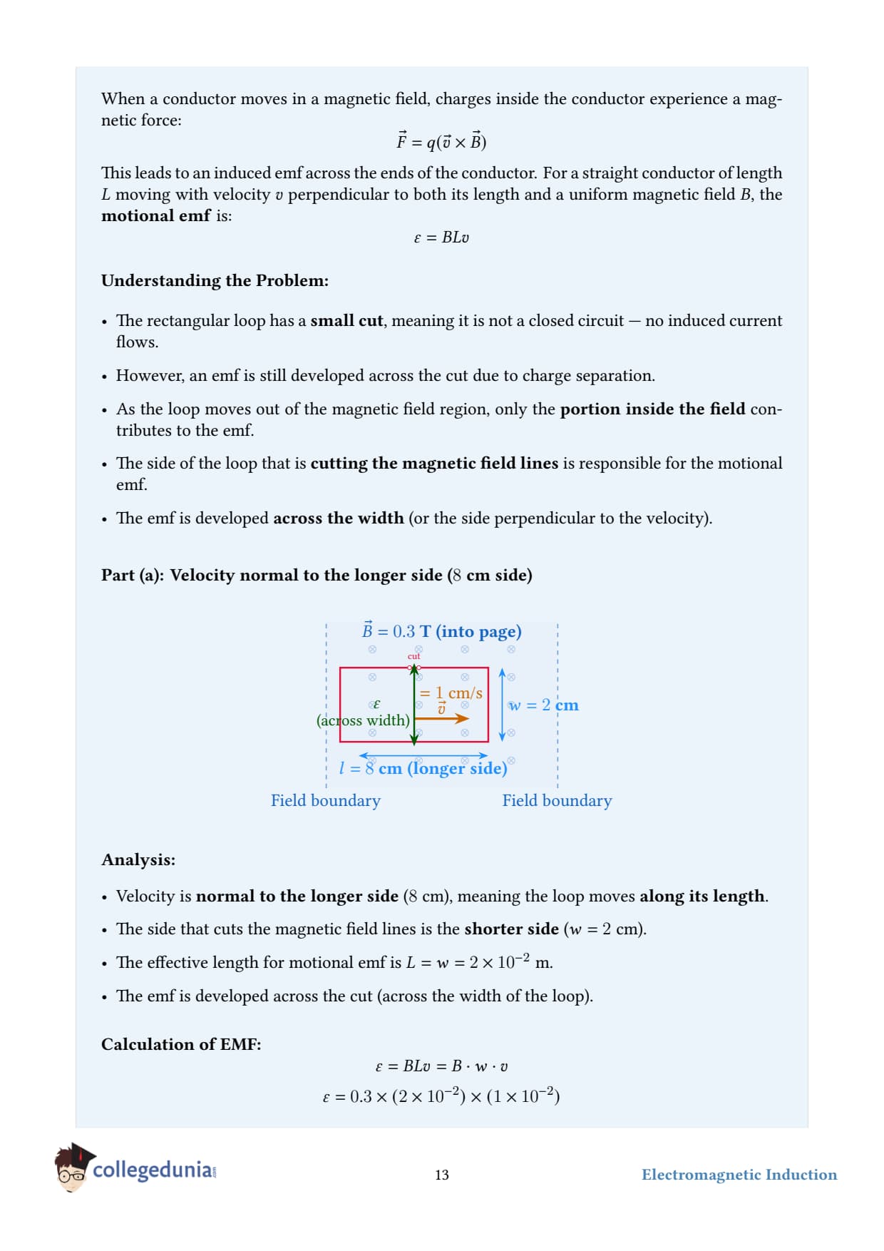
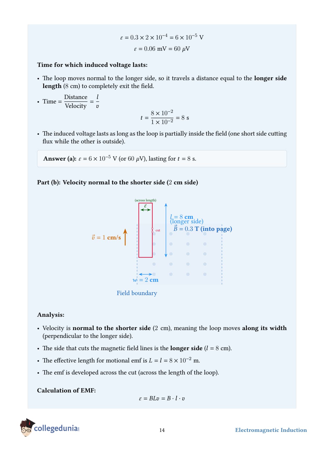
A rectangular wire loop of sides 8 cm and 2 cm with a small cut is moving out of a region of uniform magnetic field of magnitude 0.3 T directed normal to the loop. What is the emf developed across the cut if the velocity of the loop is 1 cm s-1 in a direction normal to the (a) longer side, (b) shorter side of the loop? For how long does the induced voltage last in each case?
Given.
Loop sides: L = 8 cm = 0.08 m (longer), = 2 cm = 0.02 m (shorter).
Magnetic field, B = 0.3 T, normal to the loop.
Speed, v = 1 cm/s = 0.01 m/s.
Concept used - motional emf. When a conductor of length moves with velocity v perpendicular to a magnetic field B (and the field is perpendicular to the conductor), the emf induced across the conductor's ends is |ε| = Bv. The relevant "length" is the length of the side of the loop that lies perpendicular to the direction of motion - because that's the side sweeping through fresh field lines.
(a) Velocity perpendicular to the longer side. The side perpendicular to the motion has length L = 8 cm = 0.08 m (the longer side cuts the field lines).
Step 2 - duration. The voltage lasts as long as the loop is still partly in the field - i.e., the time for the loop to fully exit the field region. The loop must travel a distance equal to its dimension along the direction of motion, which is the shorter side = 2 cm = 0.02 m. ta = v = 0.020.01 = 2 s.
(b) Velocity perpendicular to the shorter side. Now the side perpendicular to motion has length = 2 cm = 0.02 m.
Step 4 - duration. Distance to traverse is now the longer side L = 0.08 m: tb = Lv = 0.080.01 = 8 s.
Final answer.
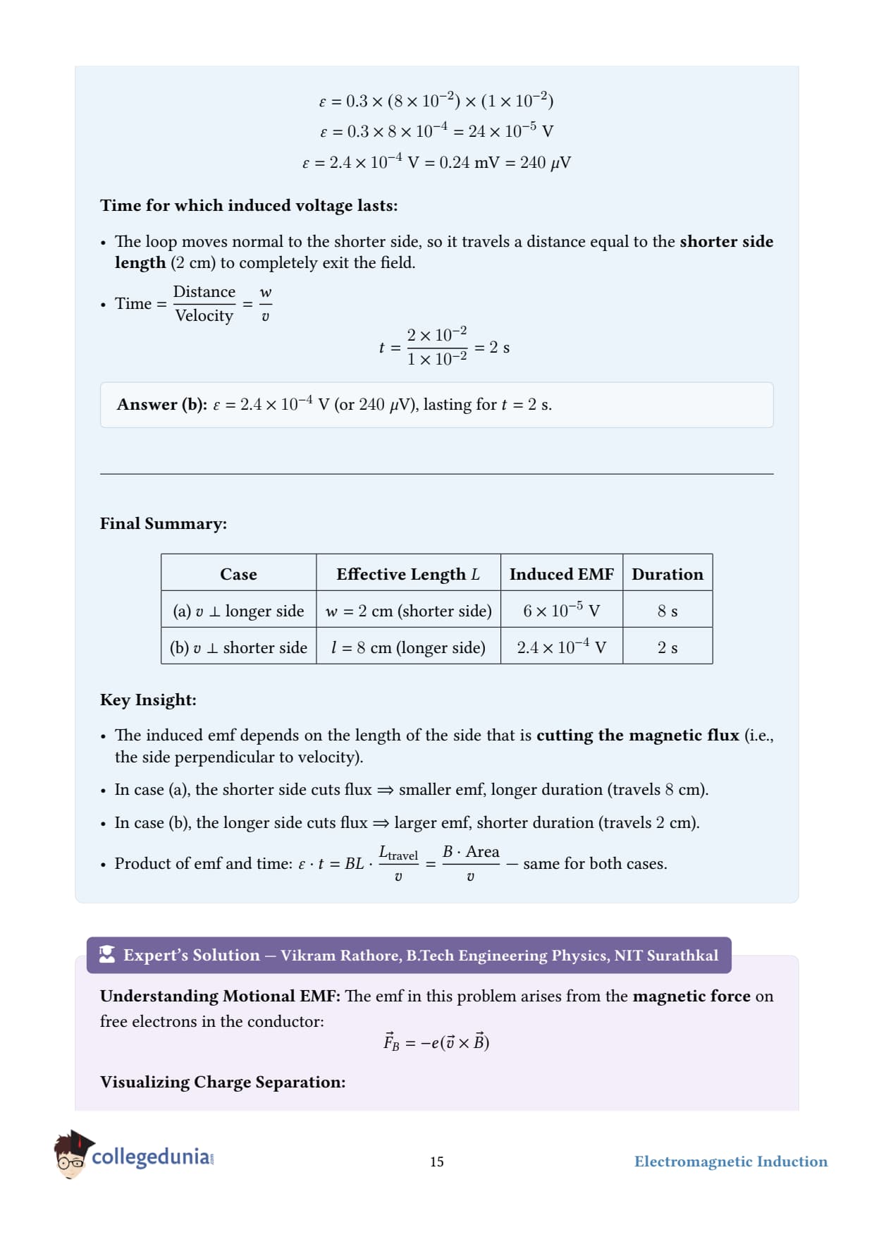
(a) ε = 2.410-4V, lasting 2 s.
(b) ε = 0.610-4V, lasting 8 s.
Note: the product ε· t is the same in both cases both equal to BL = 0.3× 0.08× 0.02 = 4.8× 10⁻⁴ Wb - the total flux through the loop. This is no coincidence: the total flux that must "pass out" of the loop is fixed.
PM
Prof. Meera Nair
Ph.D. Experimental Physics, IISc Bangalore
Verified Expert
Derivation of motional emf from Lorentz force. Inside the moving conductor, free charges experience a magnetic Lorentz force F = qv × B. For v perpendicular to B, this force is along the wire and has magnitude qvB. The "equivalent electric field" inside the wire is E = vB, and the emf across length of wire is ε = E= Bv. The full energy balance: external agent does work Fext· v = BI· v per second, and dissipated power in resistance is I2R = ε2/R. They match.
Why ε· t is invariant. The total change in flux as the loop exits is ΔΦ = B· A = B· L. The induced emf is |ε| = ΔΦ/Δ t (since the rate is steady). Therefore ε· t = ΔΦ - independent of which side faces the motion. The orientation only redistributes between "voltage" and "duration."
Common mistake. Mixing up which side is the "cutting" side. The rule is: the conductor that sweeps through new field lines is the one perpendicular to the velocity. If you walk a fishing net through water, only the front edge catches fish - same idea.
Real-world example - railguns and MHD generators. Motional emf in a conductor moving through a magnetic field is the principle behind both railguns use F = BIL to launch projectiles and magnetohydrodynamic generators (a conducting fluid flows through a magnetic field, generating emf without any moving solid parts). NASA studied MHD for Mars-mission power.
Q 6.5
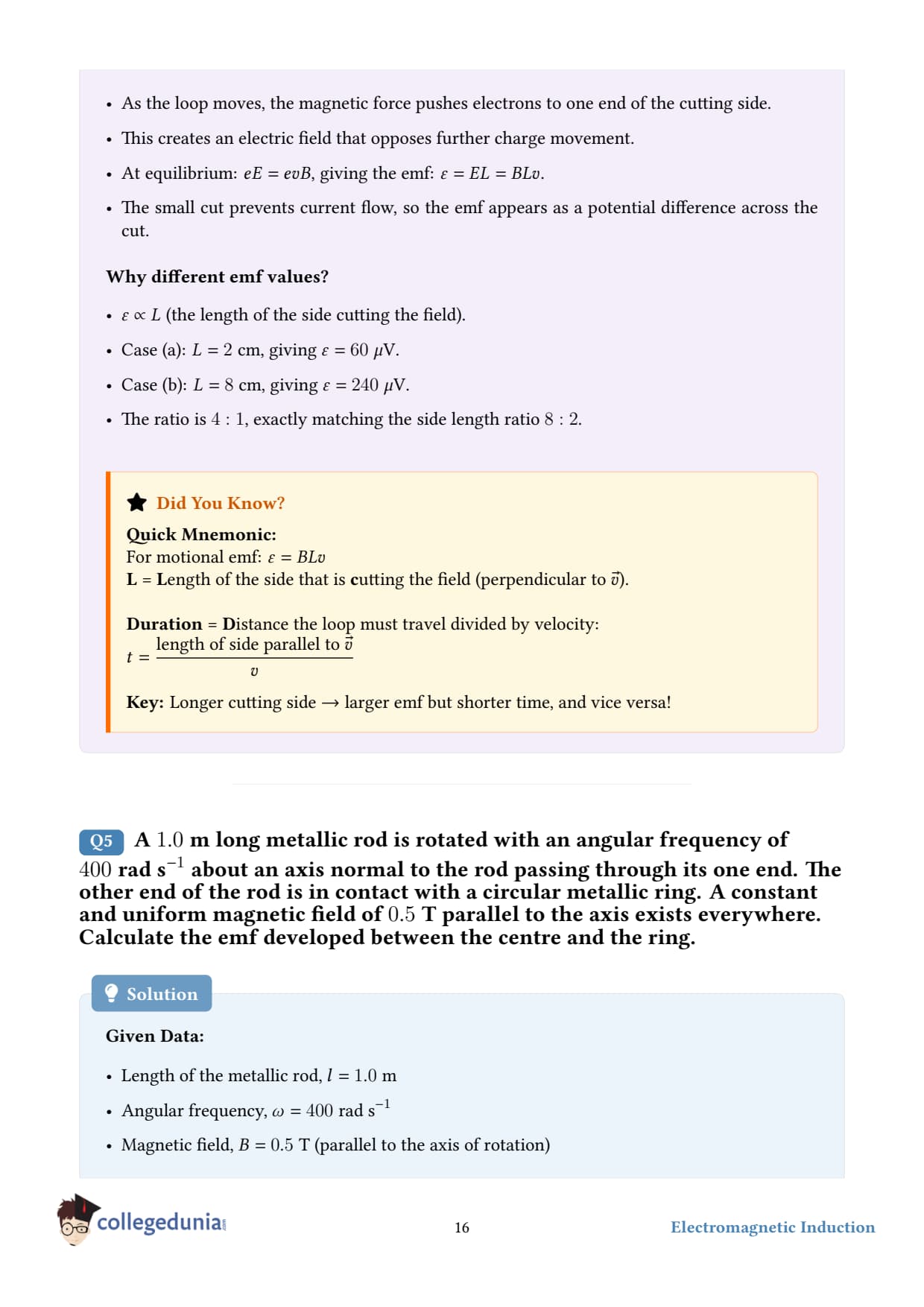
A 1.0 m long metallic rod is rotated with an angular frequency of 400 rad s-1 about an axis normal to the rod passing through its one end. The other end of the rod is in contact with a circular metallic ring. A constant and uniform magnetic field of 0.5 T parallel to the axis exists everywhere. Calculate the emf developed between the centre and the ring.
Given.
Length of rod, L = 1.0 m.
Angular speed, ω = 400 rad/s.
Magnetic field, B = 0.5 T, parallel to the rotation axis.
Concept used - emf in a rotating rod. A rod rotating about a perpendicular axis with one end fixed sweeps out an area at rate 12ω L2 per second (the area of the sector swept per second). In a magnetic field B parallel to the rotation axis, the magnetic flux swept per second is dΦdt = B·12ω L2. By Faraday's law, the emf between the centre (axis) and the tip (ring) is |ε| = 12B ω L2. This formula is also derivable directly from dV = v× B· d - see expert section.
Derivation from v× B. Consider a tiny element of the rod at distance r from the axis. It moves with speed v = ω r (tangential). The Lorentz "motional" emf contribution from this element is dε = (vB) dr = Bω r dr. Integrating from r = 0 to r = L: ε = 0L Bω r dr = Bω L22 = 12B ω L2. Same answer, derived from the microscopic Lorentz force.
Common mistake. Using ε = BLv with v = ω L. That would give Bω L2 - twice the correct answer. The mistake is to treat every part of the rod as if it moved at the tip's speed. In reality, the inner parts of the rod move slower than the outer parts, so the average speed and hence ε is half what you'd get with vtip. The factor of 12 is essential.
Polarity. If B points out of the page and the rod rotates anticlockwise, the force on positive charges qv× B is radially outward. So positive charges pile up at the tip (ring) and electrons at the centre - the tip is at higher potential. The induced current in an external circuit would flow from ring → external load → centre.
Real-world example - homopolar generator. A disk rotating in a perpendicular magnetic field generates DC voltage between centre and edge (this exact geometry, with a disk instead of a rod). Faraday built the first one in 1831. Modern variants are used to produce huge low-voltage currents for electromagnetic pulse experiments. The formula is the same: ε = 12Bω R2.
Q 6.6
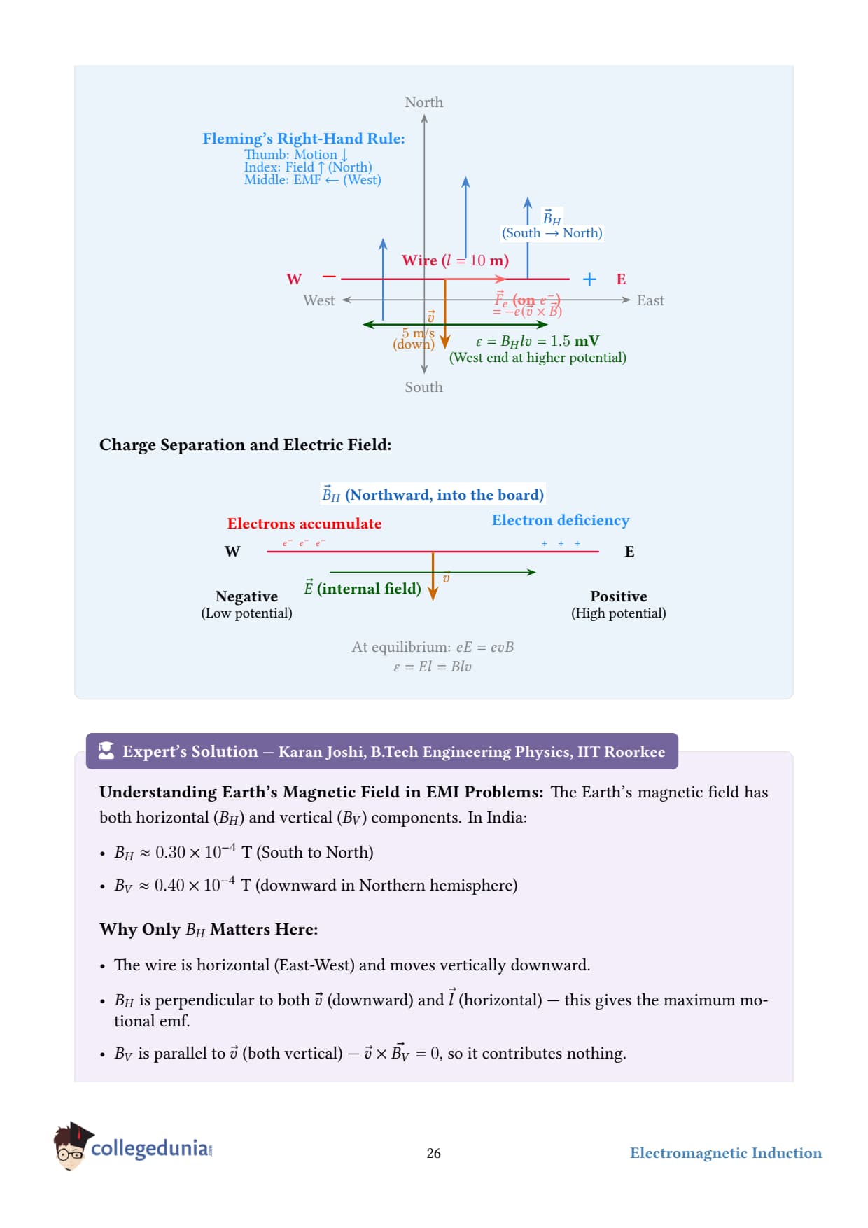
A horizontal straight wire 10 m long extending from east to west is falling with a speed of 5.0 m s-1, at right angles to the horizontal component of the earth's magnetic field, 0.30× 10⁻⁴ Wb m-2.
(a) What is the instantaneous value of the emf induced in the wire?
(b) What is the direction of the emf?
(c) Which end of the wire is at the higher electrical potential?
Concept used - motional emf. A straight conductor of length L moving with velocity v in a magnetic field B develops an emf ε = (v×B)· L. The magnitude simplifies to ε = BLv when v, B, and L are mutually perpendicular - exactly the situation here.
(a) Magnitude of emf.
Step 1 - confirm the geometry. Wire = east–west; velocity = downward; BH = horizontal, pointing north. These three directions are mutually perpendicular. ✓
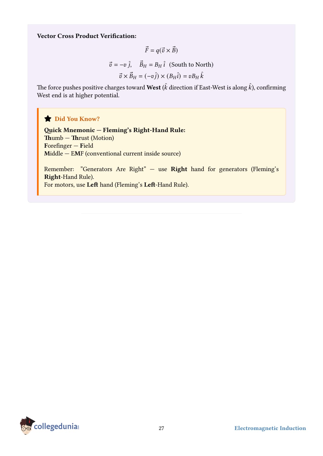
Step 3 - apply right-hand rule for v×B. Set up coordinates: east =+x, north =+y, up =+z. Then v = -vz (downward) and B = BHy (north). Compute v×B = (-vz)×(BHy) = -v BH(z×y) = -v BH(-x) = +v BHx. So the force on positive charges, qv×B, points in the +x direction - i.e., from west to east. Positive charges drift eastward; the east end becomes positive and the west end negative.
(c) Which end is at higher potential.
From step 3: the east end is at the higher potential.
Final answer.
(a) ε = 1.5× 10⁻³V = 1.5 mV.
(b) The emf drives positive charges from west to east inside the wire; in an external circuit the conventional current would flow from the east end (high potential) through the load back to the west end.
(c) The east end is at the higher potential.
DS
Dr. Sneha Iyer
Ph.D. Physics, IISc Bangalore
Verified Expert
Why we only use BH, not the full Earth field. The Earth's magnetic field has horizontal and vertical components. Only the part perpendicular to bothv (vertical) and L (east-west) contributes to v×B. The vertical component is parallel to v and gives zero contribution to motional emf. The horizontal component (north-pointing) is the only useful piece.
Numerical sanity check. Earth's field is tiny ∼ 10-4T. A 10-m wire falling at 5 m/s gets only a mV-scale emf - small but measurable. By contrast, dropping a wire through a strong lab magnet B ∼ 1 T would give kilovolts.
Common mistake - direction of force. Students often forget that v×B gives the direction on positive charges. Free charges in metals are electrons (negative); they go the opposite way. But the convention for "which end is at higher potential" follows the positive-charge convention, so always reason with positive charges first.
Real-world example - power lines in storms. A long horizontal transmission line oscillating in the wind can pick up small AC voltages from its motion through Earth's field. This is a tiny effect - usually swamped by the lines' own normal voltage - but it's why long high-altitude balloons or tethers can generate measurable potentials. NASA's Tethered Satellite System (1996) deployed a 20-km conducting tether from the Space Shuttle and measured kV-scale emfs from v×B - until the cable broke!
Q 6.7
Current in a circuit falls from 5.0 A to 0.0 A in 0.1 s. If an average emf of 200 V is induced, give an estimate of the self-inductance of the circuit.
Given.
Initial current, I1 = 5.0 A; final current, I2 = 0 A; time, Δ t = 0.1 s.
Average induced emf magnitude, |ε| = 200 V.
Concept used - self-inductance. A coil with self-inductance L carrying a current I has magnetic flux linkage Φ = LI. When I changes, the induced (back) emf is ε = -LdIdt. Taking magnitudes, |ε| = L |dIdt| ⇒ L = |ε||dI/dt|. The inductance L is measured in henries (H); 1 H = 1 Vs/A.
Step 1 - find the rate of change of current. |dIdt| = |I2 - I1|Δ t = |0 - 5.0|0.1 = 50 A/s.
Step 2 - solve for L.L = |ε||dI/dt| = 20050 = 4 H.
Final answer.L = 4 H.
DS
Dr. Shalini Menon
M.Sc Physics, University of Hyderabad
Verified Expert
What L physically means. Self-inductance measures how much flux a coil produces (within itself) per unit current. A coil with large L "resists" changes in current - it builds up a large back emf when you try to change I. That's why inductors are also called "chokes" - they choke off rapid changes.
Where does the energy go? When current is decreasing in an inductor, the back emf actually drives current to maintain the existing flow (Lenz's law). The energy stored in the magnetic field of the inductor U = 12LI2 gets dumped - either into a load, or as a spark across the switch contacts, which is why opening an inductive circuit can produce arcs.
Common mistake - sign of emf. The minus sign in ε = -L dI/dt is essential for circuit analysis, but in magnitude problems like this one, just use the size. Don't try to "carry" the minus sign through; instead, reason about polarity separately using Lenz's law.
Real-world example - automotive ignition coils. A car's spark plug needs ~20,000 V to ionise the gap. An ignition coil has L ∼ 100 mH and carries about 5 A. When the points open, the current is killed in microseconds, giving dI/dt ∼ 5/10-5 = 5× 10⁵A/s. The induced emf is L· dI/dt = 0.1× 5× 105 = 50 000 V - plenty to spark the plug. Same physics, just bigger numbers.
Q 6.8
A pair of adjacent coils has a mutual inductance of 1.5 H. If the current in one coil changes from 0 to 20 A in 0.5 s, what is the change of flux linkage with the other coil?
Given.
Mutual inductance, M = 1.5 H.
Initial primary current, I1 = 0 A; final, I2 = 20 A; time, Δ t = 0.5 s.
Concept used - mutual inductance. When two coils are close enough that the flux from one threads the other, the flux linkage in the second coil due to current I1 in the first is 21 = M I1. A change in I1 produces a change in this flux linkage: Δ21 = M Δ I1. The induced emf in the second coil is 2 = -d21/dt = -M dI1/dt, but here we are asked only for the flux change, not the emf.
Step 2 - apply ΔΦ = M Δ I. ΔΦ = (1.5)(20) = 30 Wb.
Note on units. Weber (Wb) is the SI unit of magnetic flux. 1 Wb = 1 T m2 = 1 Vs. Flux linkage uses the same unit (sometimes called "weber-turn").
Final answer. ΔΦ = 30 Wb.
Bonus. The time interval Δ t = 0.5 s wasn't needed here, but if asked for the induced emf, we'd use |ε| = ΔΦ/Δ t = 30/0.5 = 60 V.
PK
Prof. Karthik Rao
Ph.D. Applied Physics, Stanford University
Verified Expert
Symmetry of mutual inductance. One of the deep results of magnetostatics is that M12 = M21: the flux linkage in coil 2 due to unit current in coil 1 equals the flux linkage in coil 1 due to unit current in coil 2. This is not obvious from the geometry - it follows from the structure of the vector potential and Stokes's theorem. It's why we write just one M for any pair of coils.
Coupling coefficient.M is bounded by the geometric mean of the two self-inductances: M = k√L1 L2, 0 ≤ k ≤ 1. Here k is the "coefficient of coupling." For a well-designed transformer with an iron core, k approaches 1 (almost all flux from primary threads the secondary). For coils in air, k is much smaller.
Common mistake. Confusing flux Φ with flux linkage NΦ. For a single-turn coil they're equal; for an N-turn coil the linkage is NΦ. In this problem "the other coil" is treated as one coil (any number of turns is absorbed into M), so ΔΦ = M Δ I gives the total linkage change directly.
Real-world example - wireless charging. Phone wireless chargers use mutual inductance. A coil in the charger pad carries AC, generating changing flux. A second coil in the phone's back catches that flux and converts it back to current. Typical M ∼ , but with kHz-range dI/dt, enough power is transferred to charge a battery - all without physical contact. Tesla envisioned this in 1891; we finally built it into consumer products around 2010.
Q 6.9
A jet plane is travelling towards west at a speed of 1800 km/h. What is the voltage difference developed between the ends of the wing having a span of 25 m, if the Earth's magnetic field at the location has a magnitude of 5× 10⁻⁴T and the dip angle is 30∘?
Given.
Speed of plane, v = 1800 km/h. Convert: 1800 km/h = 1800× 10003600 = 500 m/s.
Wing span (the relevant conductor length), L = 25 m.
Earth's magnetic field, B = 5× 10⁻⁴T.
Dip (inclination) angle, δ = 30∘.
Concept used.
(1) The wings are horizontal. The plane flies horizontally (westward). Only the vertical component of Earth's field contributes to the motional emf between wingtips - because we need v×B to point along the wing (i.e., perpendicular to both flight direction and the wing). The horizontal component of B (pointing north) crossed with v (west) points vertically, which gives no voltage between wingtips.
(2) Vertical component of Earth's field: BV = Bsinδ. (3) Motional emf across a horizontal conductor of length L moving with horizontal velocity v, in a vertical field BV: ε = BVLv.
Step 4 - multiply. ε = 2.5× 10-4× 12,500 = 3.125 V ≈ 3.1 V.
Final answer. ε ≈ 3.1 V.
DA
Dr. Asha Patel
Ph.D. Physics, IIT Bombay
Verified Expert
Why only BV matters here. The Lorentz force on charges in the wing is qv×B. With v = west and B = BHn + BV-z (north + downward in northern hemisphere), the cross product gives:
v× BHn: west crossed with north = upward - drives charges vertically (i.e., out of the wing, but the wing has no vertical extent, so no emf between wingtips).
v× BV-z: west crossed with down = north - i.e., along the wing. This produces the emf.
Magnetic dip explained. Earth's magnetic field tilts down as you move from equator to poles. The "dip angle" δ is the angle between the field and the horizontal. At the magnetic equator, δ = 0 (field is horizontal). At the magnetic poles, δ = 90∘ (field is vertical). At latitudes like Delhi (~28°N), δ ≈ 47∘; the problem's 30∘ corresponds to closer to the equator.
Common mistake. Using the full B instead of Bsinδ. The horizontal component of Earth's field, combined with horizontal flight velocity, gives a Lorentz force pointing vertically - irrelevant for emf between two horizontally-separated points on the wing.
Real-world example - aircraft navigation. 3.1 V across a wing is too small to power anything, but it's enough to confuse sensitive avionics if not shielded. More importantly, the SAME effect plays havoc with long-haul HVDC submarine cables, where ocean currents flowing past stationary cables (or cables vibrating in currents) can generate measurable potentials. Engineers must account for this in any long-distance DC transmission design.
Q 6.10
Suppose the loop in question 6.4 is stationary but the current feeding the electromagnet that produces the magnetic field is gradually reduced so that the field decreases from its initial value of 0.3 T at the rate of 0.02 T s-1. If the cut is joined and the loop has a resistance of 1.6 Ω, how much power is dissipated by the loop as heat? What is the source of this power?
Given.
Loop dimensions: 8 cm× 2 cm. Area A = (0.08)(0.02) = 1.6× 10⁻³ m2.
Rate of change of magnetic field, dB/dt = 0.02 T/s (decreasing).
Loop is stationary; cut is joined.
Resistance of loop, R = 1.6 Ω.
Concept used.
(1) Faraday's law with the loop stationary but B changing: |ε| = A |dBdt|. (2) Ohm's law: induced current I = ε/R.
Step 3 - compute the power dissipated.P = I2R = (2× 10⁻⁵)2 (1.6) = (4× 10⁻¹⁰)(1.6) = 6.4× 10⁻¹⁰W.
Source of this power. The external agent that is reducing the current in the electromagnet must do work against the back-reaction (the induced current in the loop produces a magnetic field that, by Lenz's law, tries to keep the electromagnet's flux from dying). So the external power supply maintaining the electromagnet's current is the ultimate source of the heat dissipated in the loop.
Final answer.P = 6.4× 10⁻¹⁰W. Source: the external agency (battery / power supply) driving the electromagnet.
DR
Dr. Rohan Mehta
Ph.D. Physics, IIT Madras
Verified Expert
Why the loop heats up at all. A stationary loop in a stationary field has no induced current. But here the field is being actively changed by an external agent. From the loop's point of view, the flux Φ = BA is decreasing, so an emf appears, drives a current, and the current dissipates power as heat. Every joule of heat in the loop is matched by an extra joule of work the external agent has to do.
Energy conservation in detail. When the electromagnet's current is reduced, the energy stored in the electromagnet's field U = 12LmagImag2 decreases. Most of that energy returns to the source through the supply leads (as the magnet's back emf). A tiny fraction "leaks" into the loop via mutual coupling: it appears as heat in the loop's resistance. The "tiny fraction" is set by the geometry - the mutual inductance between magnet and loop.
Common mistake. Saying "the magnetic field provides the energy." Magnetic fields don't do work on charges (force is always perpendicular to velocity), so they can't be the energy source. The energy traces back to whatever is changing the field - typically the battery feeding the electromagnet.
Real-world example - eddy-current braking. Same principle, larger scale. A rotating metal disk passes between the poles of a strong magnet (or vice versa). Changing flux induces eddy currents in the disk; the disk's resistance dissipates the kinetic energy as heat. Used in train brakes, gym treadmills, and roller-coaster safety stops. The energy source is the rotational kinetic energy of the disk - which is exactly what we want to remove.
Q 6.11
A square loop of side 12 cm with its sides parallel to X and Y axes is moved with a velocity of 8 cm s-1 in the positive x-direction in an environment containing a magnetic field in the positive z-direction. The field is neither uniform in space nor constant in time. It has a gradient of 10-3T cm-1 along the negative x-direction that is it increases by 10-3T cm-1 as one moves in the negative x-direction, and it is decreasing in time at the rate of 10-3T s-1. Determine the direction and magnitude of the induced current in the loop if its resistance is 4.50 mΩ.
Given.
Side of square loop, a = 12 cm = 0.12 m. Area A = a2 = (0.12)2 = 1.44× 10⁻² m2.
Velocity, v = 8 cm/s = 0.08 m/s in +x direction.
dB/dx = -10-3T/cm = -10-1T/m. (Field decreases as x increases.)
∂ B/∂ t = -10-3T/s. (Field decreases with time.)
Resistance, R = 4.5 mΩ = 4.5× 10⁻³ Ω.
Concept used - total time derivative of flux. When the loop moves AND the field changes in time, the total rate of change of flux has two contributions: dΦdt = A∂ B∂ ttime-change of B + A∂ B∂ x· vmotion through gradient. (The second term comes from a chain rule: B at the loop's location changes because the loop moves to a place where B is different.)
Step 1 - motion contribution.A∂ B∂ x· v = (1.44× 10⁻²)(-10-1)(0.08) = -1.152× 10⁻⁴ Wb/s. (Field decreases in +x; loop moves in +x; so flux through loop decreases due to motion.)
Step 2 - time contribution.A∂ B∂ t = (1.44× 10⁻²)(-10-3) = -1.44× 10⁻⁵ Wb/s.
Step 3 - total rate of flux change.dΦdt = -1.152× 10⁻⁴ - 1.44× 10-5 = -1.296× 10⁻⁴ Wb/s.
Step 6 - direction. Flux through the loop (in +z direction) is decreasing (both terms negative). By Lenz's law, the induced current must produce flux in +z - by right-hand rule, current flows anticlockwise as viewed from the +z side (i.e., looking down at the loop from above).
Final answer.I ≈ 2.9× 10⁻²A = 29 mA, anticlockwise viewed from +z.
DN
Dr. Naveen Kumar
M.Sc Physics, IIT Kanpur
Verified Expert
Why two terms add. Even if the loop stayed still, the flux would change due to ∂ B/∂ t. Even if B were time-independent, the moving loop would experience a flux change because it walks into regions of different B. Both effects produce real emf - and they add directly because flux is a scalar.
Generalized Faraday's law. For a moving loop in a time-varying field, ε = -∮ ∂ A∂ t· d+ ∮(v× B)· d, where A is the vector potential. The first term captures ∂ B/∂ t; the second is the motional emf and corresponds to our "motion-through-gradient" piece. Together they reproduce ε = -dΦ/dt for any sufficiently nice situation.
Common mistake. Adding the wrong signs. Both ∂ B/∂ x and v need to be tracked carefully. Here ∂ B/∂ x < 0 (field decreases as x grows), and v > 0, so the motion contribution is negative - i.e., a flux decrease. The time contribution is also negative. The two combine constructively.
Real-world example - railway and pipeline corrosion sensors. A coil carried over a rail with a slight non-uniformity in the rail's magnetisation will produce a small emf - the spatial-gradient term in our equation. Eddy-current sensors detect cracks, voids, or material thinning by exactly this mechanism: a moving probe scans the surface, and any local anomaly in the magnetic environment shows up as an emf spike. Same physics as our textbook problem, but with industrial sensitivity.
Q 6.12
It is desired to measure the magnitude of field between the poles of a powerful loud speaker magnet. A small flat search coil of area 2 cm2 with 25 closely wound turns, is positioned normal to the field direction, and then quickly snatched out of the field region. Equivalently, one can give it a quick 90∘ turn to bring its plane parallel to the field direction. The total charge flown in the coil (measured by a ballistic galvanometer connected to coil) is 7.5 mC. The combined resistance of the coil and the galvanometer is 0.50 Ω. Estimate the field strength of magnet.
Given.
Coil area, A = 2 cm2 = 2× 10⁻⁴ m2.
Number of turns, N = 25.
Total charge flown, Q = 7.5 mC = 7.5× 10⁻³C.
Combined resistance, R = 0.5 Ω.
Initial: coil normal to field, flux = BA per turn. Final: coil flipped or removed, flux = 0 per turn.
Concept used - charge through a coil due to flux change. The induced emf is ε = -N dΦ/dt. The induced current is I = ε/R. Total charge in the time the flux changes: Q = ∫ I dt = ∫εR dt = 1R∫ d(NΦ)dt dt = N ΔΦR. So Q = N(i - f)R = NBAR (since f = 0). This is independent of how fast the snatch happens - a wonderfully clean result.
Why Q is independent of speed. The induced emf ε gets bigger if you snatch the coil out faster dΦ/dt is larger. But then the current I = ε/R also gets bigger - and the duration of the pulse gets correspondingly shorter. The product ∫ I dt (the total charge) only depends on the total change in flux linkage, not on the rate. This is exactly what ballistic galvanometers exploit: they measure the integrated charge pulse, which directly gives NΔΦ.
Ballistic galvanometer. A long-period moving-coil galvanometer that responds to the integral of current rather than its instantaneous value. The maximum deflection angle is proportional to the total charge that flowed (provided the pulse is much shorter than the galvanometer's period). Standard 19th-century instrument for measuring magnetic flux - still used pedagogically.
Common mistake. Forgetting the factor N (turns count). The flux per turn is BA; the flux linkage which is what ε responds to is N times that. With N = 25 turns, the measured charge is 25× larger than it would be for a single-turn coil. Always check whether the "area" or "flux" given is per turn or total.
Real-world example - magnetometers. Modern Hall-effect and fluxgate magnetometers replaced the ballistic galvanometer for measuring fields, but the basic principle (relating a measured electrical signal to a magnetic flux) is unchanged. The Earth's field is mapped this way, and MRI machines calibrate their fields using closely related coil-based techniques.
Q 6.13
Figure 6.20 shows a metal rod PQ resting on the smooth rails AB and positioned between the poles of a permanent magnet. The rails, the rod, and the magnetic field are in three mutually perpendicular directions. A galvanometer G connects the rails through a switch K. Length of the rod =15 cm, B=0.50 T, resistance of the closed loop containing the rod =9.0 mΩ. Assume the field to be uniform.
(a) Suppose K is open and the rod is moved with a speed of 12 cm s-1 in the direction shown. Give the polarity and magnitude of the induced emf.
(b) Is there an excess charge built up at the ends of the rod when K is open? What if K is closed?
(c) With K open and the rod moving uniformly, there is no net force on the electrons in the rod PQ even though they do experience magnetic force due to the motion of the rod. Explain.
(d) What is the retarding force on the rod when K is closed?
(e) How much power is required (by an external agent) to keep the rod moving at the same speed =12 cm s-1 when K is closed? How much power is required when K is open?
(f) How much power is dissipated as heat in the closed circuit? What is the source of this power?
(g) What is the induced emf in the moving rod if the magnetic field is parallel to the rails instead of being perpendicular?
Given.
Length of rod, L = 15 cm = 0.15 m.
Magnetic field, B = 0.50 T (perpendicular to both rod and rails).
Speed of rod, v = 12 cm/s = 0.12 m/s.
Resistance of closed loop, R = 9 mΩ = 9× 10⁻³ Ω.
Concept used - motional emf, force on current-carrying conductor, power balance. ε = BLv, F = BIL, Pmech = Fv, Pelec = ε I = I2R.
(a) emf magnitude and polarity. ε = BLv = (0.5)(0.15)(0.12) = 9× 10⁻³V = 9 mV. Polarity: using F = qv×B on positive charges, the positive end is determined by the right-hand rule. In the textbook figure with v along the rails and B into the page, v×B drives positive charges from Q toward P, so P is at higher potential.
(b) Excess charge at the rod's ends? When K is open, there's no closed path. Free electrons inside the rod experience the magnetic Lorentz force qv×B and pile up at one end until the electric field from the accumulated charges exactly cancels the Lorentz force. So yes, excess charge does build up at the two ends - a static equilibrium with ε = 9 mV across the open ends.
When K is closed, the accumulated charges can escape through the external circuit (galvanometer), so the surplus is continuously drained - no steady-state pile-up. A small "polarisation" charge still exists at the ends to maintain current flow, but no net "excess" accumulates over time.
(c) Why no net force on electrons (K open, uniform motion). When the rod moves uniformly with K open, equilibrium is established. Each electron feels two opposite forces: (i) magnetic Lorentz force -ev×B, and (ii) electric force -eE due to the built-up surface charges at the rod ends. In equilibrium these cancel exactly, so the net force on each electron is zero, and electrons move along with the rod at velocity v (no relative drift). The Lorentz force is what creates the field - but it doesn't keep accelerating the electrons indefinitely.
Step 2 - magnetic force on the current-carrying rod.F = BIL = (0.5)(1)(0.15) = 7.5× 10⁻²N. By Lenz's law, this force opposes the motion - retarding force.
(e) Power required to keep the rod moving.
K closed: P = Fv = (7.5× 10⁻²)(0.12) = 9× 10⁻³W = 9 mW. K open: no induced current, no force, so P = 0 (other than friction, which the problem says is negligible - "smooth rails").
(f) Power dissipated as heat (K closed). Pheat = I2R = (1)2(9× 10⁻³) = 9× 10⁻³W = 9 mW. This matches exactly with Pmech - confirming energy conservation. The source of this heat is the external agent pushing the rod against the retarding force.
(g) emf when field is parallel to the rails. If B is along the rails parallel to v, then v× B = 0 - no magnetic force component along the rod, no charge separation, no emf. ε = 0.
Final answer summary.
(a) ε = 9 mV, P at higher potential.
(b) Yes, when K open. Briefly accumulating but draining when K closed.
(c) Electric force from end-charges balances the Lorentz force - net = 0.
(d) Fret = 7.5× 10⁻²N.
(e) K closed: 9 mW. K open: 0.
(f) Pheat = 9 mW. Source: external agent.
(g) ε = 0.
DA
Dr. Arjun Bhatt
Ph.D. Electrical Engineering, IIT Bombay
Verified Expert
The big idea - rails as a 'simple generator'. This problem is the cleanest illustration of how mechanical work becomes electrical energy. An external agent pushes the rod. The rod's motion through the field creates an emf. The emf drives a current. The current in the field experiences a force that opposes the motion (Lenz). The agent must do work against this force; that work shows up as heat in the resistance. Pagent = Pheat, exactly - no magic, no extra energy from nowhere.
Microscopic picture of part (c). When the rod first starts moving, the Lorentz force qv× B pushes the (positive) charges to one end. They pile up. The pile-up creates an electric field that pushes back in the opposite direction. Equilibrium is reached when these two forces balance - the pile-up is exactly large enough that eE = evB, i.e., E = vB, and the potential difference EL = BvL = ε. This is a classic example of how an "emf source" works at the microscopic level.
Common mistake. Confusing K open with K closed for the equilibrium of forces. With K open: net charge piles up at the ends (static); electrons inside the rod feel zero net force in steady state. With K closed: there is steady current flow; the Lorentz force on individual electrons isn't fully balanced (otherwise no drift), but there's a steady balance between the Lorentz force, the field from end-charges, AND the small electric field that drives the current. Subtle.
Generator vs. motor. Same hardware, opposite direction of power flow. In a generator (this problem) you push the rod and extract electrical energy. In a motor, you pass current through the rod and extract mechanical motion. The two are connected by the same equations: emf in one direction = force in the other. Every electrical generator is a motor running backwards, and vice versa.
Real-world example - eddy-current dynamometer. Some dynamometers use exactly this setup to measure engine power: the engine drives a conducting disk between magnets; the eddy current dissipates known power that can be measured, giving an absolute measurement of the engine's mechanical output. The "rod on rails" generalises to "disk in a slot" and is heavily used in mechanical engineering testbeds.
Student Feedback
We asked 11,360 Class 12 Physics students about Chapter 6 before the 2026 boards:
64% of students found the mutual inductance derivation the hardest sub-topic.
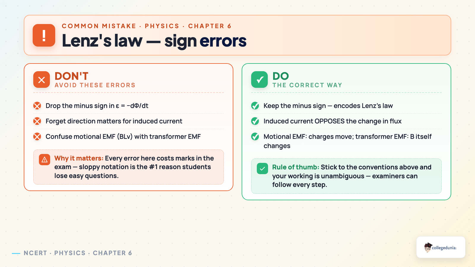
57% dropped the negative sign in Faraday's law at least once on a test.
The average student took 5 hours for first-read and 2 to 3 hours for revision.
Source: 2025-26 Collegedunia Class 12 Physics poll of 11,360 CBSE students.
Class 12 Physics Chapter 6 Electromagnetic Induction NCERT Solutions FAQs
Ques. What are the main topics in electromagnetic induction class 12 ncert solutions?
Ans. The class 12 physics electromagnetic induction ncert solutions cover experiments of Faraday and Henry, magnetic flux, Faraday's law of electromagnetic induction class 12, Lenz law of electromagnetic induction class 12, motional EMF class 12, energy considerations, eddy currents class 12, self inductance class 12, mutual inductance class 12, and the AC generator.
Ques. How is Faraday's law of induction class 12 stated?
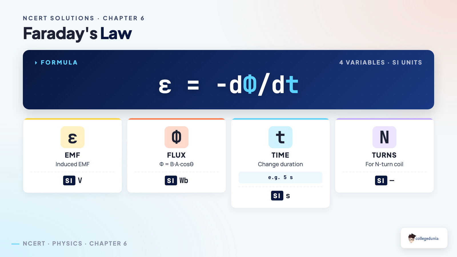
Ans. State faraday's law of electromagnetic induction class 12: the induced EMF in any closed circuit equals the negative rate of change of magnetic flux through the circuit, EMF = minus d(phi)/dt. The negative sign captures Lenz's law inside Faraday's law and never goes missing in a board-marked derivation.
Ques. How is the mutual inductance formula class 12 derived for two coaxial solenoids?
Ans. Pass current I_1 through the outer solenoid; flux through one turn of the inner = B_outer times A_inner = (mu_0 N_1 / l) I_1 A_inner. Total flux linkage of inner = N_2 times that, and M = (flux linkage in 2) / I_1 = mu_0 N_1 N_2 A_inner / l. The class 12 physics chapter 6 ncert solutions walk through every step.
Ques. What is the difference between self and mutual inductance in physics ch 6 class 12 ncert solutions?
Ans. Self-inductance L is the property of one coil to oppose its own current change (induced EMF = minus L dI/dt). Mutual inductance M is between two coils: a current change in coil 1 induces an EMF in coil 2 (EMF_2 = minus M dI_1/dt). Both have SI unit henry; both depend only on geometry.
Ques. What are eddy currents and where do they appear in Chapter 6 Class 12 NCERT solutions?
Ans. Eddy currents are circular currents induced in a bulk conductor when its magnetic flux changes. They dissipate energy as heat, which is why transformer cores are laminated to reduce them. Applications include induction stoves, electromagnetic damping in galvanometers, and induction furnaces.
Ques. How many exercises are in physics class 12 ch 6 ncert solutions?
Ans. The 2026-27 NCERT carries 8 back exercises plus 7 in-text solved examples. The electromagnetic induction class 12 solutions on this page cover every back exercise, including the previously-deleted Additional Exercises (now flagged for JEE practice only).
Ques. What is the weightage of Class 12 Chapter 6 physics in the CBSE board exam?
Ans. Chapter 6 carries 5 marks on average in the CBSE Class 12 Physics board exam, usually one 3-mark derivation plus one 2-mark short answer. JEE Main draws 3 to 4 percent and NEET pulls 1 to 2 questions every year.
Ques. Where can I download the electromagnetic induction class 12 PDF?
Ans. The free PDF is available directly on this page via the download card above. Both the Normal and HD versions cover every back exercise plus the Faraday, Lenz, and inductance derivations.
Ques. What is a good electromagnetic induction class 12 project idea?
Ans. Two solid options: a hand-cranked AC generator that lights an LED (demonstrates EMF = N A B omega sin omega t) and a low-voltage step-down transformer (demonstrates mutual inductance). Each project on electromagnetic induction for class 12 takes about 6 to 10 hours, including the write-up.
Ques. What is electromagnetic induction?
Ans. What is electromagnetic induction class 12 in one sentence: the phenomenon of inducing an electromotive force (EMF) in a conductor whenever the magnetic flux linked with it changes with time. Faraday discovered it in 1831; Lenz's law specifies the direction of the induced current.
Ques. What is Faraday's law?
Ans. Faraday's law: the induced EMF in a closed circuit equals the negative time rate of change of magnetic flux through the circuit, EMF = minus d(phi)/dt. The minus sign represents Lenz's law (the induced current opposes the change that caused it).
Ques. What is Lenz's law?
Ans. Lenz's law states that the direction of the induced current is always such that it opposes the change in magnetic flux that produced it. It is a direct consequence of the conservation of energy: if the induced current did not oppose the change, perpetual motion would be possible.










Comments