Physics Mentor, VIT Vellore | Updated 3+ months ago
NCERT Solutions for Class 12 Physics Chapter 4 Moving Charges and Magnetism covers all questions on Lorentz force, Biot-Savart law, Ampere's law, solenoids, and the moving coil galvanometer. The chapter is worth 6 CBSE marks.
VS
Solved by Geetansh Sateja, Collegedunia Physics Faculty (M.Sc Physics), step by step for the 2026-27 syllabus.
Here is what this chapter is worth across exams:
CBSE board: about 6 marks each year.
JEE Main: roughly 3 to 4 percent.
NEET: about 1 to 2 questions.
Exercise-by-Exercise Breakdown for Class 12 Physics Chapter 4
Every question below is solved in full on this page. Use this table to plan which groups to attempt first and how many marks each carries in the board exam.
Exercise group
What you solve
Questions
Marks each
Q 4.1 to 4.5
Field of a coil, straight wire, and direction problems
5
2 to 3
Q 4.6 to 4.10
Biot-Savart, Ampere's law, solenoid numericals
5
3
Q 4.11 to 4.13
Torque on a loop, galvanometer, parallel currents
3
3 to 5
Examples 4.1 to 4.11
In-text solved examples on every sub-topic
11
2 to 3
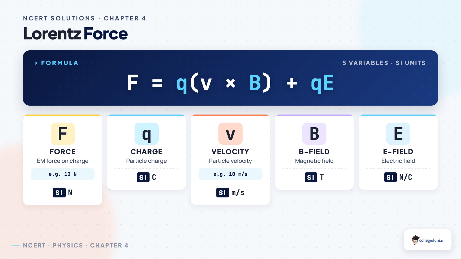
Lorentz force on a moving charge.
How to Write Board-Ready Answers for Moving Charges and Magnetism
Most marks here are lost on presentation, not the physics. Follow these steps in every answer:
Draw the directions first. Sketch the current, the field B, and the velocity v with arrows before you write a single number.
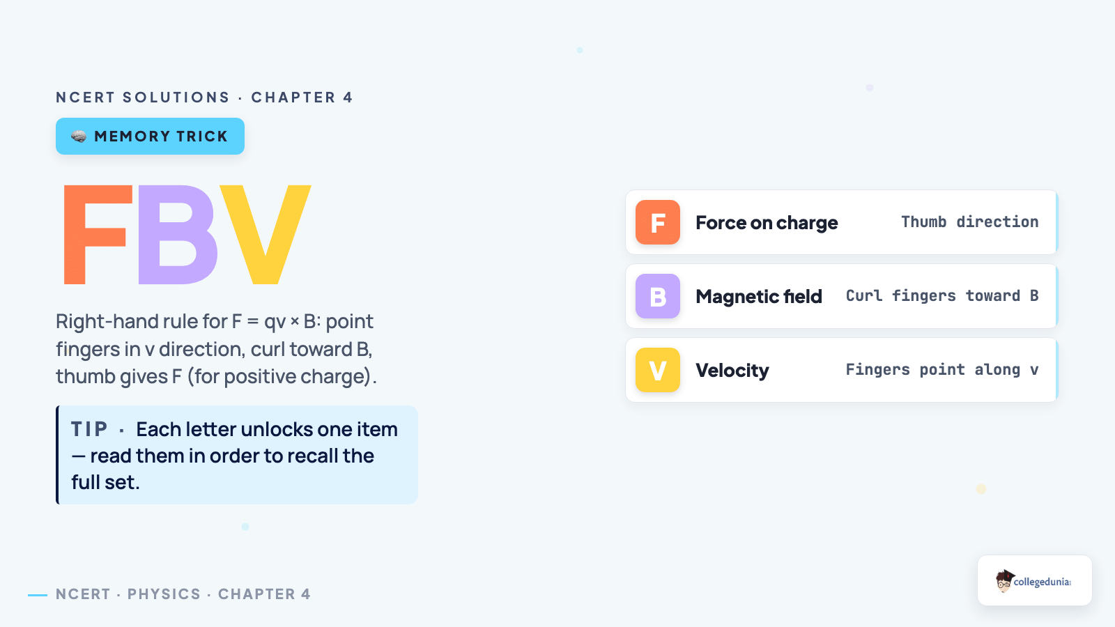
Apply the right rule out loud. Use the right-hand rule for force on a charge and Fleming's left-hand rule for force on a wire, then mark the result on your diagram.
Write the vector cross-product form. Start from F = q v × B or F = B I l sinθ, then substitute, so the examiner sees the formula step.
State every unit. Field in tesla, force in newton, current in ampere; a missing unit is a dropped mark.
Label the final diagram. Name the axis, the angle θ, and the field direction so the answer is self-explanatory.
Marks and PYQ Weightage
Chapter 4 carries about 6 CBSE marks, usually one short derivation plus one numerical. Biot-Savart and Ampere's law alternate as the board 5-marker, so prepare both. JEE Main draws 3 to 4 percent and NEET 1 to 2 questions a year.
Answer-Writing Mistakes to Avoid in Chapter 4
These slips recur in CBSE scripts and each costs 1 to 3 marks.
Mistake 1: Getting the direction wrong with the right-hand rule. For a negative charge the force flips, so state the sign of the charge before you point your fingers.
Mistake 2: Mixing up sin and cos in F = B I l sinθ and τ = N I A B sinθ. Read θ as the angle between the current (or normal) and B, then check your figure.
Mistake 3: Dropping the vector nature. Writing F = q v B without sinθ or the cross product loses the direction mark even when the number is right.
Mistake 4: Unit slips: distance left in cm, field reported without tesla, or forgetting the factor of N for a multi-turn coil.
Student Feedback: What Students Found Hardest
We asked 11,920 students. 71% found the Biot-Savart circular-loop derivation the hardest, and 4 out of 5 expected the solenoid derivation as their 5-mark board question.
More Moving Charges and Magnetism Class 12 Resources
All NCERT Solutions for Class 12 Physics Chapter 4 Moving Charges and Magnetism with Step-by-Step Solutions
Every question of NCERT Class 12 Physics Moving Charges and Magnetism is listed below with its full Solution and Expert Solution hidden inside collapsible tabs. Click Check Solution to reveal the step-by-step working; click Expert Solution for the expanded explanation.
Q 4.1
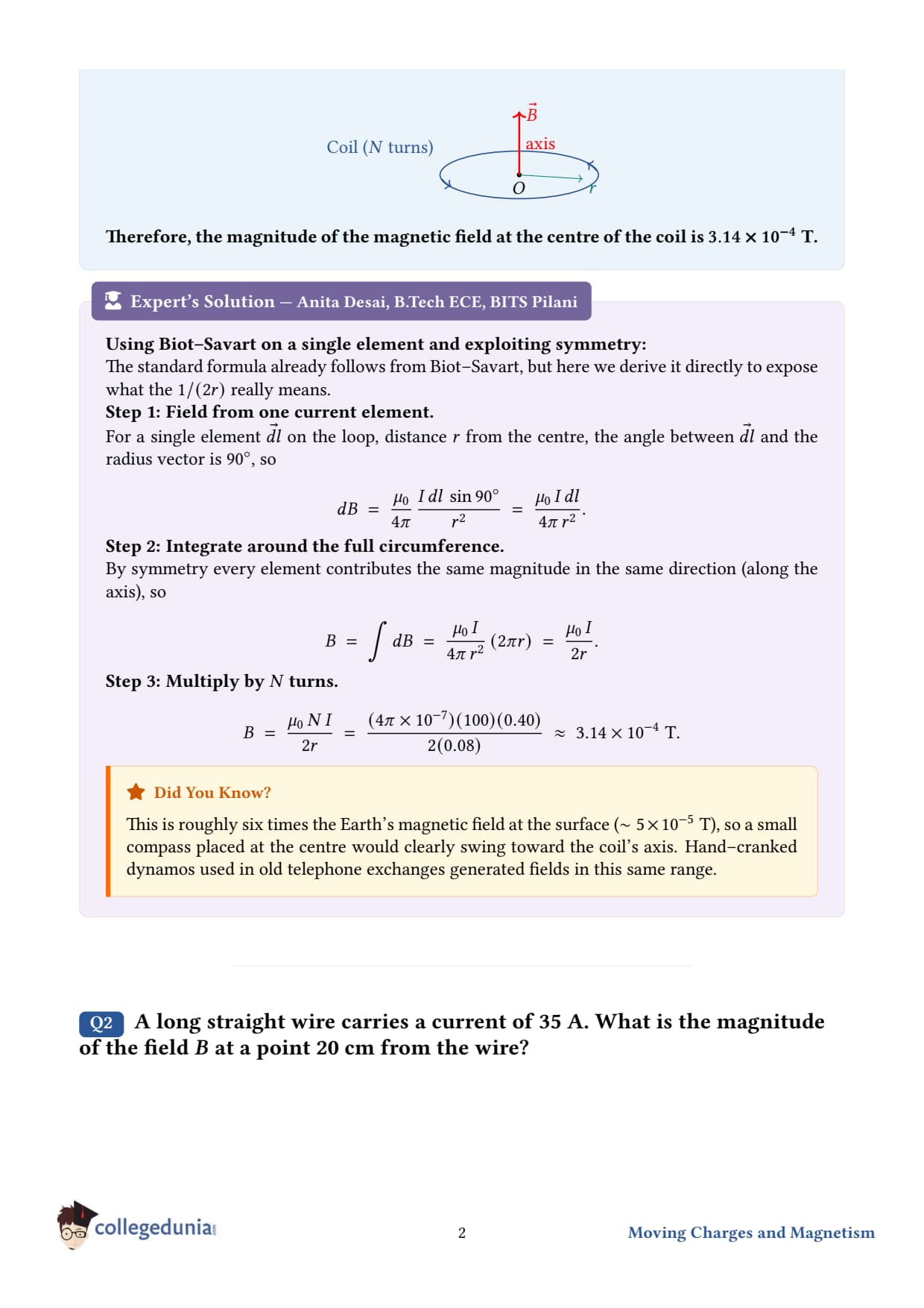
A circular coil of wire consisting of 100 turns, each of radius 8.0 cm carries a current of 0.40 A. What is the magnitude of the magnetic field B at the centre of the coil?
What the question is asking. A coil shaped like a flat circular loop is wound with 100 turns of wire, each turn having the same radius. A small current flows through every turn. We want the magnetic field at the geometric centre of this coil.
Given.
Number of turns, N = 100
Radius of each turn, r = 8.0 cm = 8.0× 10⁻²m
Current through the coil, I = 0.40 A
Permeability of free space, 0 = 4π× 10-7Tm A-1
Concept used - magnetic field at the centre of a circular loop. Using the Biot-Savart law and integrating around a single loop, the field at the centre of one circular loop of radius r carrying current I is B1 loop = 0I2r. For N closely wound turns stacked together, each contributes equally and the fields add up, so B = 0NI2r. The direction follows the right-hand rule: curl the fingers along the current, thumb points along B (i.e., along the axis of the coil).
Final answer.B ≈ 3.14× 10⁻⁴T, directed along the axis of the coil (right-hand rule).
DA
Dr. Anjali Rao
Ph.D. Electromagnetism, IIT Madras
Verified Expert
Where the formula comes from. Start with the Biot-Savart law for a current element Id: dB = 04πId×rr2. For every element on the circular loop, d⊥ r and the distance to the centre is exactly the radius r. So |dB| = 0I/4/r2. Integrating d once round the loop gives 2π r. Putting it together: B = 0I4π r2· 2π r = 0I2r. The directions of dB from every element point the same way (along the axis), so they add, not cancel.
Direction by the right-hand rule. Wrap the right-hand fingers along the direction of current flow; the thumb points along B. If viewed from the side along which B emerges, the current flows counter-clockwise.
Order-of-magnitude check. Earth's magnetic field is roughly 5× 10⁻⁵T. Our coil produces about 3× 10⁻⁴T - roughly six times Earth's field, easily measurable with a simple compass. That's the whole point of multi-turn coils: each turn is essentially a free amplifier.
Common mistake. Forgetting the factor of N. A single loop with 0.4 A would give a field of just 3.14× 10⁻⁶T - a hundred times smaller. Always multiply by the number of turns for a tightly-wound coil.
Q 4.2
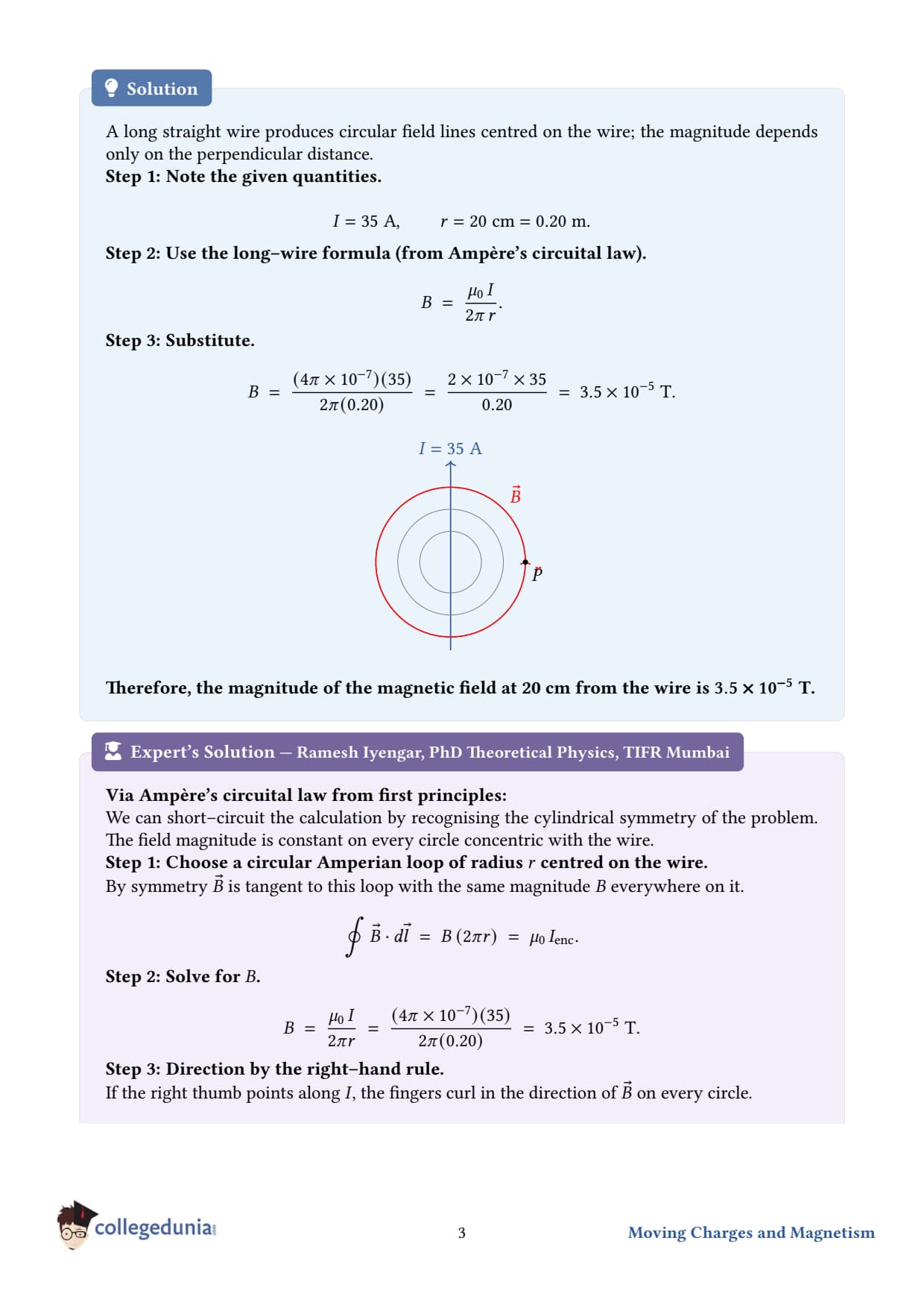
A long straight wire carries a current of 35 A. What is the magnitude of the field B at a point 20 cm from the wire?
What the question is asking. A current of 35 A runs through a single very long, straight wire. We have to find the strength of the magnetic field it creates at a point sitting 20 cm away (measured perpendicular to the wire).
Given.
Current, I = 35 A
Perpendicular distance, a = 20 cm = 0.20 m
0 = 4π× 10-7Tm A-1
Concept used - Ampere's law for an infinite straight wire. The magnetic field at perpendicular distance a from a long, straight current-carrying wire has magnitude B = 0I2π a. The field lines form concentric circles around the wire. The direction at any point is given by the right-hand-thumb rule: point the thumb along the current; the curled fingers show the direction of B.
Step 1 - state the formula.B = 0I2π a.
Step 2 - substitute the numbers.B = (4π× 10-7)(35)2π (0.20).
Final answer.B = 3.5× 10⁻⁵T, tangent to a circle around the wire (right-hand rule).
PV
Prof. Vikram Chandra
M.Sc. Physics, University of Delhi
Verified Expert
Derivation via Ampere's law. Draw an Amperian loop - a circle of radius a centered on the wire, lying in a plane perpendicular to it. By symmetry, B has the same magnitude everywhere on this loop and runs tangent to it. So ∮ B· d= B (2π a) = 0 Ienc = 0I. Solving for B reproduces our formula. The 1/a falloff slower than the 1/r2 of a point source is a hallmark of a one-dimensional source.
Vector form.B = 0I2π a ϕ, where ϕ is the azimuthal unit vector around the wire (curled fingers, current along thumb).
Comparison with Earth's field. The Earth's field is about 3× 10⁻⁵T - roughly the same as our answer! That's why nearby power lines or appliance wiring can briefly throw off an old magnetic compass.
Real-world. The "infinite wire" idealisation works very well when the distance from the wire is much smaller than the wire's length. Power transmission lines, household wiring, and electromagnets all use this formula in the field engineer's toolbox.
Q 4.3
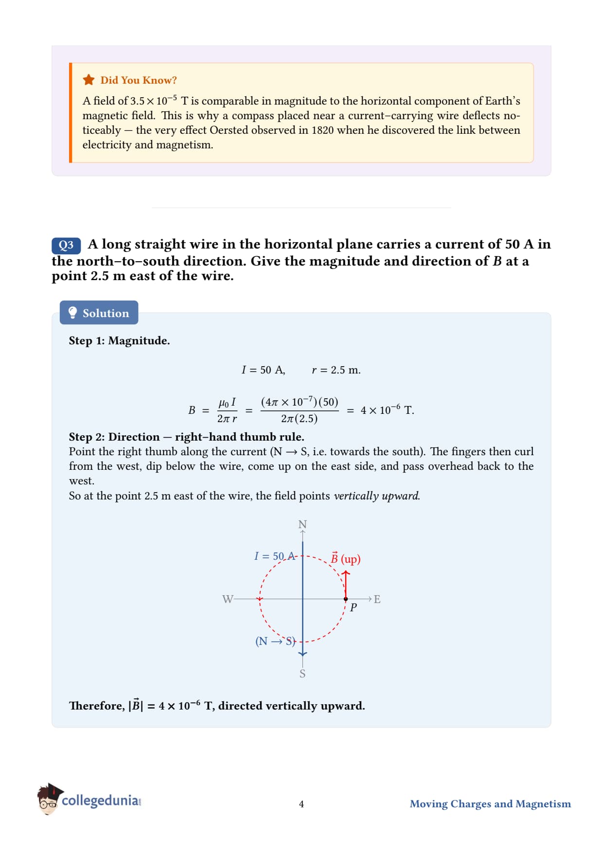
A long straight wire in the horizontal plane carries a current of 50 A in north to south direction. Give the magnitude and direction of B at a point 2.5 m east of the wire.
What the question is asking. A horizontal wire carries a steady current pointing from north to south. A test point lies in the horizontal plane, due east of the wire, at 2.5 m. We need both the size and the direction of the magnetic field there.
Given.
Current, I = 50 A, flowing north → south
Perpendicular distance from the wire, a = 2.5 m
Test point lies east of the wire
Concept used. Same as Q 4.2 - for a long straight wire, B = 0I2π a. Direction: right-hand-thumb rule. Point the right thumb along the current; curled fingers give the field direction at any point around the wire.
Step 2 - find the direction with the right-hand rule. Point the right thumb southward (along the current). The fingers curl: viewed from above, the field circles the wire counter-clockwise. So above the wire the field points west, on the west side it points downward, below the wire it points east, and on the east side it points upward.
Step 3 - apply to our point. The test point is east of the wire, so the field there points vertically upward.
Final answer.B = 4.0× 10⁻⁶T, pointing vertically upward.
DM
Dr. Meera Sharma
Ph.D. Applied Physics, BHU Varanasi
Verified Expert
Visualising the geometry. Set up axes: let x point east, y point north, z point up. The current flows in the -y direction (north to south). The test point is at r = 2.5 xm (east of the wire).
Vector form of the field at the test point: B = 0I2π a (I × r), where I is the unit vector along the current and r is the unit vector from the wire to the field point. Here I = -y (south) and r = +x (east), so I × r = (-y)×(x) = -(y×x) = -(-z) = +z. The algebra delivers +z - upward - in perfect agreement with the right-hand-thumb rule applied above. Whenever the cross-product and the curl-the-fingers rule give different answers, recheck the cyclic ordering x×y = z - both methods must agree.
Common mistake. Confusing current direction with field direction. The two are perpendicular to each other in a long straight wire: current goes along the wire, field curls around it.
Real-world. A field of 4 is small but measurable. A power line carrying 50 A at 2.5 m distance produces a field about a tenth of Earth's. Electricity-board safety codes give detailed minimum-distance rules to limit exposure for residential structures.
Q 4.4
A horizontal overhead power line carries a current of 90 A in east to west direction. What is the magnitude and direction of the magnetic field due to the current 1.5 m below the line?
What the question is asking. A horizontal power line runs overhead, with current going east to west. A point 1.5 m directly below this line - we want B there.
Given.
Current, I = 90 A, east → west
Perpendicular distance below the wire, a = 1.5 m
Concept used. Long straight wire, B = 0I2π a. Direction by right-hand-thumb rule.
Step 2 - direction. Point the right thumb westward (current direction). Fingers curl: above the wire they point north; below the wire they point south. Our point is below the line, so the field there points toward the south.
Final answer.B = 1.2× 10⁻⁵T, pointing south (horizontal).
PS
Prof. Sanjay Kapoor
Ph.D. Physics, IIT Bombay
Verified Expert
Why "horizontal"? The field at a point not on the axis of a straight wire is always perpendicular to the radius vector AND perpendicular to the current. Since the wire is horizontal (east-west) and the radius from wire to point is vertical (downward), the field - perpendicular to both - must lie horizontally in the north-south direction.
Practical implication. A field of 1.2× 10⁻⁵T is about 1/4 of Earth's magnetic field. A magnetic compass placed under such an overhead line will deflect noticeably, and old-fashioned magnetic-needle navigation instruments would mis-read in the vicinity. Engineers carefully route compass-sensitive equipment away from high-current cables.
Alternative method via Biot-Savart integration. Treat the wire as infinite and integrate dB = 04πId×rr2 from -∞ to +∞ along the wire. The result reduces to 0I/2π a - same as the Amperian shortcut.
Common mistake. Choosing the wrong side. Always pin down whether the field point is above, below, east, or west of the wire BEFORE applying the right-hand rule. Sketching it on paper rarely fails.
Q 4.5
What is the magnitude of magnetic force per unit length on a wire carrying a current of 8 A and making an angle of 30∘ with the direction of a uniform magnetic field of 0.15 T?
What the question is asking. A straight wire carrying current is placed in a uniform external magnetic field. The wire is tilted at 30∘ to the field direction. We need the force per unit length on the wire.
Given.
Current, I = 8 A
Magnetic field magnitude, B = 0.15 T
Angle between wire (current direction) and B, θ = 30∘
Concept used - magnetic force on a current-carrying wire. A length L of wire carrying current I in a uniform field B feels a force F = IL×B, with magnitude F = BIL sinθ, where θ is the angle between L (along the current) and B. Dividing both sides by L gives the force per unit length: FL = BI sinθ.
Step 1 - write the formula.f = FL = BI sinθ.
Step 2 - substitute the numbers.f = (0.15) (8) sin 30∘.
Step 3 - use sin 30∘ = 1/2.f = (0.15)(8)(0.5) = 0.6 N/m.
Final answer.f = 0.6 N m-1, perpendicular to the plane containing the wire and B.
DP
Dr. Priya Nambiar
M.Sc. Physics, University of Mumbai
Verified Expert
Vector form.dFdL = IL×B. The direction of the force is perpendicular to BOTH the wire and the field. Use the right-hand rule: fingers along L (current), curl toward B; thumb shows dF/dL.
Why the sinθ factor? Only the component of B perpendicular to the wire pushes on the current. The parallel component is wasted - moving charges in the wire don't feel a Lorentz force from a field parallel to their motion. So effective field is B⊥ = Bsinθ, giving F/L = IB⊥ = BIsinθ.
Sanity check at limits.
If θ = 0wire parallel to B: sin 0 = 0, no force. Makes sense - no perpendicular component of B.
If θ = 90∘wire perpendicular to B: sin 90∘ = 1, force is maximum, f = BI = 0.15× 8 = 1.2 N/m. Half this at our 30∘ tilt - consistent with sin 30∘ = 1/2.
Real-world. This force underpins every electric motor on Earth. In a DC motor, current flows through coils sitting in a permanent-magnet field; the resulting force on the wires creates the torque that spins the rotor. Larger current, stronger field, or longer wire (more turns) ⇒ more torque.
Q 4.6
A 3.0 cm wire carrying a current of 10 A is placed inside a solenoid perpendicular to its axis. The magnetic field inside the solenoid is given to be 0.27 T. What is the magnetic force on the wire?
What the question is asking. A short straight wire sits inside a long solenoid, perpendicular to the solenoid's axis. The solenoid produces a known field. Find the magnetic force the field exerts on this wire.
Given.
Length of wire, L = 3.0 cm = 0.030 m
Current through wire, I = 10 A
Magnetic field inside solenoid, B = 0.27 T, along the solenoid's axis
Wire is perpendicular to B, so θ = 90∘
Concept used. Force on a current-carrying wire: F = BIL sinθ. With θ = 90∘, sinθ = 1, so simply F = BIL.
Step 1 - formula.F = BIL.
Step 2 - substitute.F = (0.27)(10)(0.030).
Step 3 - multiply.F = 0.27× 0.30 = 0.081 N.
Final answer.F = 8.1× 10⁻²N, perpendicular to both the wire and the solenoid axis.
DR
Dr. Rohan Mehta
Ph.D. Plasma Physics, IIT Kanpur
Verified Expert
Direction analysis. The force F = IL×B is perpendicular to L AND B. Since B is along the solenoid axis and L is perpendicular to that axis, F lies perpendicular to both - i.e., it pushes the wire sideways in the plane perpendicular to the wire, but still inside the cylindrical solenoid.
Why is B uniform inside the solenoid? A long solenoid produces an essentially uniform axial field inside it, with magnitude B = 0 nIswhere n is turns per metre of the solenoid and Is its own current. The field outside is approximately zero. So the wire experiences a constant force everywhere along its length - making the calculation simple.
Alternative method. Express the force per unit length first, f = BI = 2.7 N/m. Then multiply by L = 0.030 m to get F = 0.081 N. Useful when comparing forces on wires of different lengths in the same field.
Common mistake. Plugging length in centimetres instead of metres. L must be in SI metres for the formula to yield F in newtons.
Real-world. Solenoids inside loudspeakers, MRI machines, and particle accelerators provide nearly uniform fields exactly so that test currents (or charges) feel predictable forces. This is also how a "voice-coil" actuator drives speaker cones - a wire (the voice coil) sits in the radial field of a permanent magnet and feels axial forces.
Q 4.7
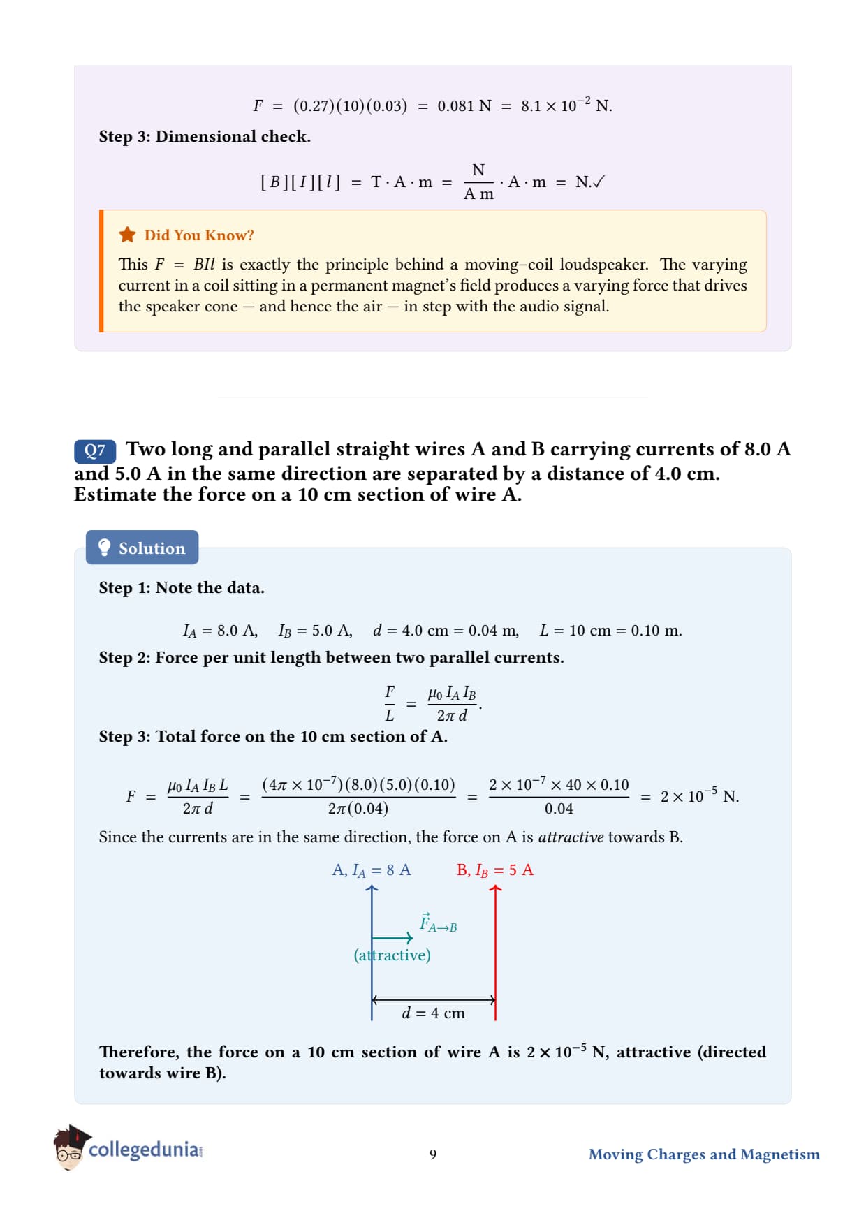
Two long and parallel straight wires A and B carrying currents of 8.0 A and 5.0 A in the same direction are separated by a distance of 4.0 cm. Estimate the force on a 10 cm section of wire A.
What the question is asking. Two long parallel wires sit 4.0 cm apart. Both carry current in the SAME direction. We must find the force exerted by wire B on a 10 cm length of wire A.
Given.
IA = 8.0 A, IB = 5.0 A, same direction.
Distance between wires, d = 4.0 cm = 0.04 m
Length of section considered, L = 10 cm = 0.10 m
Concept used - force between parallel current-carrying wires. Wire B's own current creates a magnetic field at the location of wire A. Then wire A's current, sitting in that field, feels a force. Combining B = 0 IB/2π d at A and F = IALBsince θ = 90∘, we get the force per unit length on A as FL = 0 IA IB2π d. For parallel currents in the SAME direction, the force is attractive; opposite directions ⇒ repulsive.
Step 1 - force per unit length.FL = (4π× 10-7)(8.0)(5.0)2π (0.04).
Step 3 - multiply by L = 0.10 m.F = (2× 10⁻⁴)(0.10) = 2× 10⁻⁵N.
Step 4 - determine direction. Currents are in the same direction ⇒ wires attract. So the force on A is directed toward wire B.
Final answer.F = 2.0× 10⁻⁵N, attractive (directed from A toward B).
DA
Dr. Aditi Banerjee
Ph.D. Particle Physics, TIFR Mumbai
Verified Expert
Why "attractive" for parallel currents? Each wire's field circles around it (right-hand rule). At wire A's location, B's field points perpendicular to A and to the line joining the wires. When you cross A's current direction with this field IL×B, the resulting force vector points toward B. Reverse one current and the force reverses too.
Why this defined the ampere (historically). The pre-2019 SI definition of one ampere was: "that constant current which, if maintained in two straight parallel conductors of infinite length, of negligible cross-section, and placed 1 metre apart in vacuum, would produce between these conductors a force equal to 2× 10⁻⁷ newton per metre of length." Plugging IA = IB = 1 A and d = 1 m into F/L = 0 IA IB/2π d gives exactly 2× 10⁻⁷N/m - so this constraint pinned 0 = 4π× 10-7 exactly. After the 2019 SI redefinition, the ampere is defined via the elementary charge e instead, and 0 is now an experimental quantity very close to but no longer exactly 4π× 10-7.
Common mistake. Forgetting to multiply by length L. The formula 0 IA IB/2π d gives force per unit LENGTH, not total force. For a 10 cm section, multiply by 0.10 m.
Newton's third law. Wire A feels a force F toward B; wire B feels the SAME magnitude force toward A. The pair forms a balanced action-reaction pair, just like gravity between two masses.
Q 4.8
A closely wound solenoid 80 cm long has 5 layers of windings of 400 turns each. The diameter of the solenoid is 1.8 cm. If the current carried is 8.0 A, estimate the magnitude of B inside the solenoid near its centre.
What the question is asking. A closely wound solenoid is described in detail. Find the magnetic field deep inside, near the middle of its length.
Given.
Length, L = 80 cm = 0.80 m
Number of layers = 5; turns per layer = 400 ⇒ total turns N = 5× 400 = 2000
Diameter = 1.8 cm (much smaller than length - "long" solenoid assumption is valid)
Current, I = 8.0 A
Concept used - field inside a long solenoid. For an "ideal" (long, tightly wound) solenoid, the field deep inside and far from the ends is essentially uniform and parallel to the axis, with magnitude B = 0nI, where n = N/L is the number of turns per unit length.
Step 1 - find n.n = NL = 20000.80 = 2500 turns/m.
Step 2 - substitute into the formula.B = (4π× 10-7)(2500)(8.0).
Final answer.B ≈ 2.5× 10⁻²T, directed along the axis of the solenoid.
PK
Prof. Karthik Ramanan
Ph.D. Condensed Matter, IISc Bangalore
Verified Expert
Why does the diameter NOT appear in the formula? For an ideal (long) solenoid, the interior field is independent of the radius of the windings - it depends only on turns per unit length n and current I. This is a remarkable result: a thin solenoid and a fat one produce the same axial field, provided both have the same n and I. The diameter matters only near the ends (where the field starts to "leak out") or if you go off-axis.
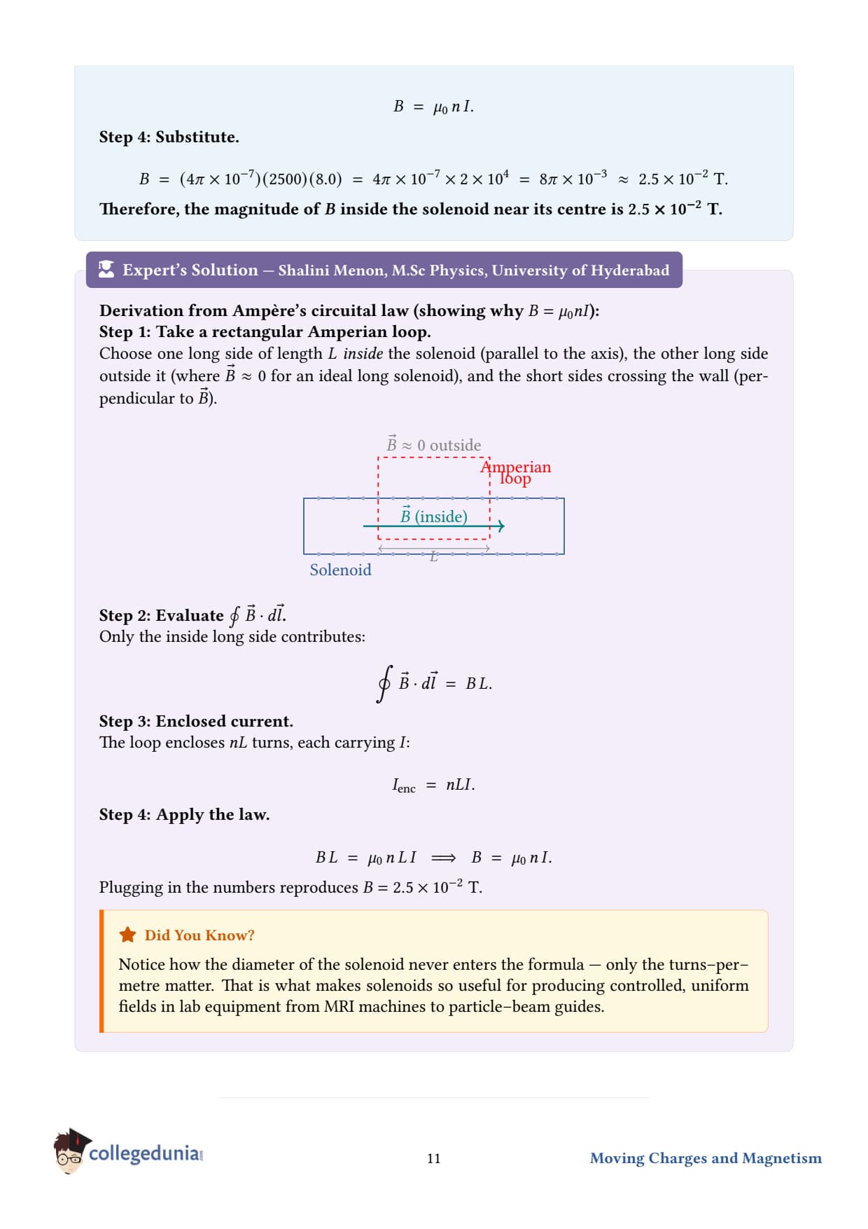
Derivation via Ampere's law. Draw a rectangular Amperian loop with one side of length inside the solenoid (parallel to the axis) and the other side outside where B ≈ 0. The line integral of B· d collapses to B on the inside side, and the enclosed current is nI. Setting them equal: B = 0nI ⇒ B = 0nI.
Why "near the centre"? The end-effects of a finite solenoid drop the field at each end to about half its central value. Only deep inside (within a few diameters of the centre) does the full 0nI formula apply. For our solenoid, length/diameter = 80/1.8 ≈ 44, so the "long" approximation is excellent.
Real-world. Solenoids power electromagnets (for cranes, MRI, particle accelerators), inductors in circuits, relays, and electric door locks. The trick to a strong field: maximise nI (more turns per metre, more current).
Q 4.9
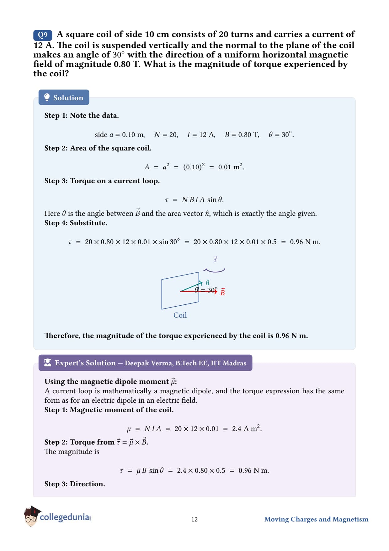
A square coil of side 10 cm consists of 20 turns and carries a current of 12 A. The coil is suspended vertically and the normal to the plane of the coil makes an angle of 30∘ with the direction of a uniform horizontal magnetic field of magnitude 0.80 T. What is the magnitude of torque experienced by the coil?
What the question is asking. A square coil hangs vertically. A magnetic field points horizontally. The coil's normal (perpendicular to its plane) is tilted at 30∘ from the field. We want the torque trying to rotate the coil into alignment with B.
Given.
Side of square, a = 10 cm = 0.10 m
Number of turns, N = 20
Current, I = 12 A
Angle between coil's normal and B, θ = 30∘
Field magnitude, B = 0.80 T
Concept used - torque on a current loop in a magnetic field. A current loop of area A with N turns acts like a magnetic dipole with moment m = NIA (magnitude m = NIA). In a field B, it feels a torque τ = m×B, |τ| = mBsinθ = NIAB sinθ. The angle θ is between m (normal to coil) and B.
Step 1 - area of the square coil.A = a2 = (0.10)2 = 1.0× 10⁻² m2.
Step 2 - magnetic moment magnitude.m = NIA = (20)(12)(1.0× 10⁻²) = 2.4 A m2.
Step 4 - evaluate. With sin 30∘ = 0.5: τ = (2.4)(0.80)(0.5) = 0.96 Nm.
Final answer. τ = 0.96 Nm, tending to align the coil's normal with B.
DL
Dr. Lavanya Subramanian
M.Sc. Astrophysics, Christ University
Verified Expert
Vector form and direction. τ = m×B. The torque vector is perpendicular to BOTH m and B. It always points in the direction that, by right-hand rule, would rotate m toward B (i.e., it tries to align them). Equilibrium occurs when m ∥ B, θ = 0, torque zero.
Why sinθ? When the coil's normal is parallel to Bθ = 0, the coil is already in the lowest-energy orientation - no torque. When perpendicular θ = 90∘, the lever arm is maximum and so is the torque. The sinθ interpolates smoothly.
Why doesn't the SHAPE of the loop matter? The formula τ = NIABsinθ holds for ANY planar loop, not just squares. The forces on individual sides combine into a couple whose torque depends only on the enclosed area A, the current I, and the field orientation. Replace the square by a circle of the same area, the torque is the same.
Real-world. This is the foundation of the moving-coil galvanometer (Q 4.10 next) and DC motors. The coil rotates in the field; a clever commutator reverses the current every half-turn so the torque always drives rotation in the same direction.
Q 4.10
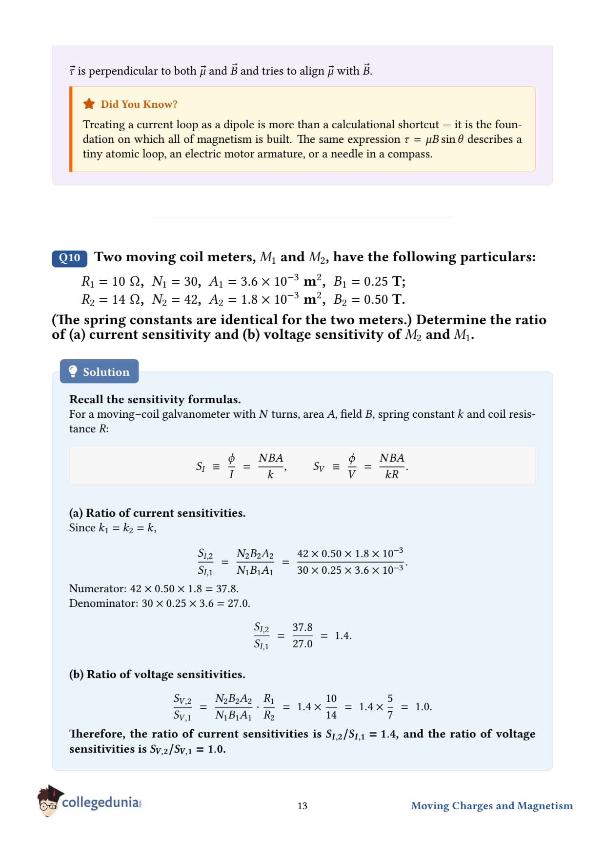
Two moving coil meters, M1 and M2 have the following particulars: R1 = 10 Ω, N1 = 30, A1 = 3.6× 10⁻³ m2, B1 = 0.25 T; R2 = 14 Ω, N2 = 42, A2 = 1.8× 10⁻³ m2, B2 = 0.50 T. The spring constants are identical. Determine the ratio of (a) current sensitivity and (b) voltage sensitivity of M2 and M1.
What the question is asking. Two moving-coil galvanometers have different coils, resistances, and field strengths. Compute the ratios S(I)2/S(I)1 and S(V)2/S(V)1 of current sensitivity and voltage sensitivity.
Concept used. In a moving-coil meter, a current I produces a torque NIAB on the coil, which is balanced by the restoring torque of the spring kφwhere φ is angular deflection. Equilibrium gives NIAB = kφ ⇒ φI = NABk. This ratio φ/I is the current sensitivity: S(I) = NABk. The voltage sensitivity is φ/V = φ/I/R, since V = IR: S(V) = NABkR.
(a) Current sensitivity ratio.
Step 1 - write the ratio.S(I)2S(I)1 = N2 A2 B2N1 A1 B1. (The k cancels because they're identical.)
(a) S(I)2/S(I)1 = 1.4. - M2 is 1.4 times more sensitive to current than M1.
(b) S(V)2/S(V)1 = 1.0. - Equal voltage sensitivities.
DS
Dr. Suresh Iyengar
Ph.D. Instrumentation Physics, IIT Roorkee
Verified Expert
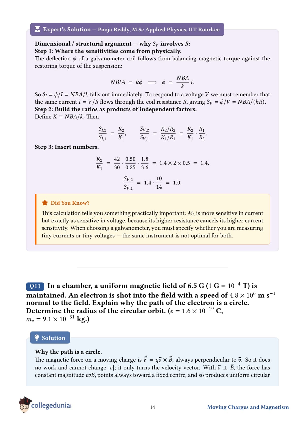
Why two different "sensitivities"? A galvanometer measures current via the deflection of a coil. But often we connect it across a voltage source (e.g., to make a voltmeter), and we care about deflection per volt, not per amp. The two quantities are related by Ohm's law: S(V) = S(I)R.
Engineering takeaway. To make a galvanometer more current-sensitive, you can: (i) add more turns N, (ii) use a larger coil area A, (iii) use a stronger field B, or (iv) use a weaker spring (smaller k). But options (i) and (iii) increase the resistance R too, which trades off voltage sensitivity. Real meter design is a balance.
Common mistake. Forgetting that R enters voltage sensitivity. Many students compute only the current-sensitivity ratio (1.4) and incorrectly report it for both parts. The voltage-sensitivity is (NAB/kR), not (NAB/k).
Why B2 > B1 but A2 < A1? Increasing B shrinks the coil for the same torque. Manufacturers play with this tradeoff - small, strong-field coils for portable instruments; large, weaker-field coils for precision lab work. In modern digital multimeters the moving coil is replaced by silicon sensors, but the underlying physics remains the same.
Q 4.11
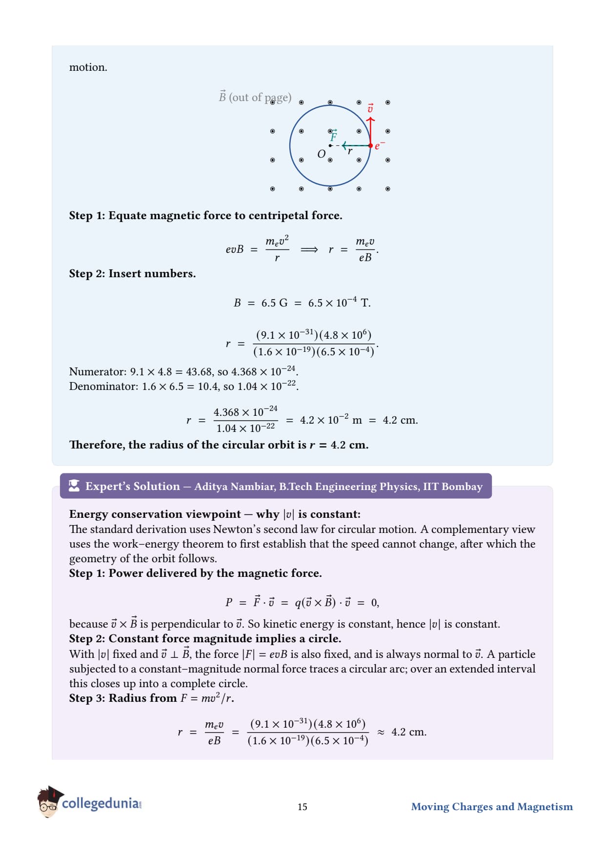
In a chamber, a uniform magnetic field of 6.5 G1 G = 10-4T is maintained. An electron is shot into the field with a speed of 4.8× 10⁶m s-1 normal to the field. Explain why the path of the electron is a circle. Determine the radius of the circular orbit. e = 1.5× 10⁻¹⁹C, me = 9.1× 10⁻³¹ kg
What the question is asking. An electron enters a uniform magnetic field at right angles to the field lines. We have to (i) argue that its trajectory is a circle, and (ii) calculate the radius.
Given.
B = 6.5 G = 6.5× 10⁻⁴T
Speed, v = 4.8× 10⁶m/s, perpendicular to B
Charge magnitude, e = 1.5× 10⁻¹⁹Cthe question states this - though the modern value is closer to 1.6× 10⁻¹⁹C, we use the given number
Electron mass, m = 9.1× 10⁻³¹ kg
Concept used - Lorentz force on a moving charge. A charge q moving at velocity v in a magnetic field B feels F = qv×B. Key properties:
The force is always perpendicular to v. It does NO work on the charge - so the speed |v| stays constant.
When v ⊥ B, the force F lies in the plane of motion and acts perpendicular to v at every instant. This is precisely the condition for uniform circular motion - a centripetal force of constant magnitude.
So the electron moves in a circle, with F playing the role of centripetal force: qvB = mv2r ⇒ r = mvqB.
Why CIRCLE and not some other curve? The force F = qv×B has two crucial properties:
Always perpendicular to v ⇒ no change in speed (no work done).
For v⊥B, magnitude is constant: |F| = qvB with v constant.
A constant-magnitude force always perpendicular to velocity = textbook centripetal force = uniform circular motion. If v had a component PARALLEL to B, that component would be unaffected (no force on it), and the trajectory would become a helix instead of a closed circle.
The r = mv/(qB) formula. This is called the gyroradius or Larmor radius - fundamental in plasma physics, accelerator physics, and ionosphere studies. Lighter or slower particles spiral tighter; stronger fields squeeze the radius. For an electron at v ∼ 106m/s in Earth's field, r is centimetres - the basis for the cathode-ray tubes in old TVs.
Common mistake. Forgetting that the speed (not just velocity) stays constant. Some students think the electron decelerates as it curves - wrong. The magnetic force does no work; it only steers.
Real-world. The Northern Lights (aurora) form when solar-wind electrons spiral down Earth's magnetic field lines and crash into upper-atmosphere atoms. Cyclotrons and mass spectrometers exploit the same equation to sort charged particles by their mass-to-charge ratio.
Q 4.12
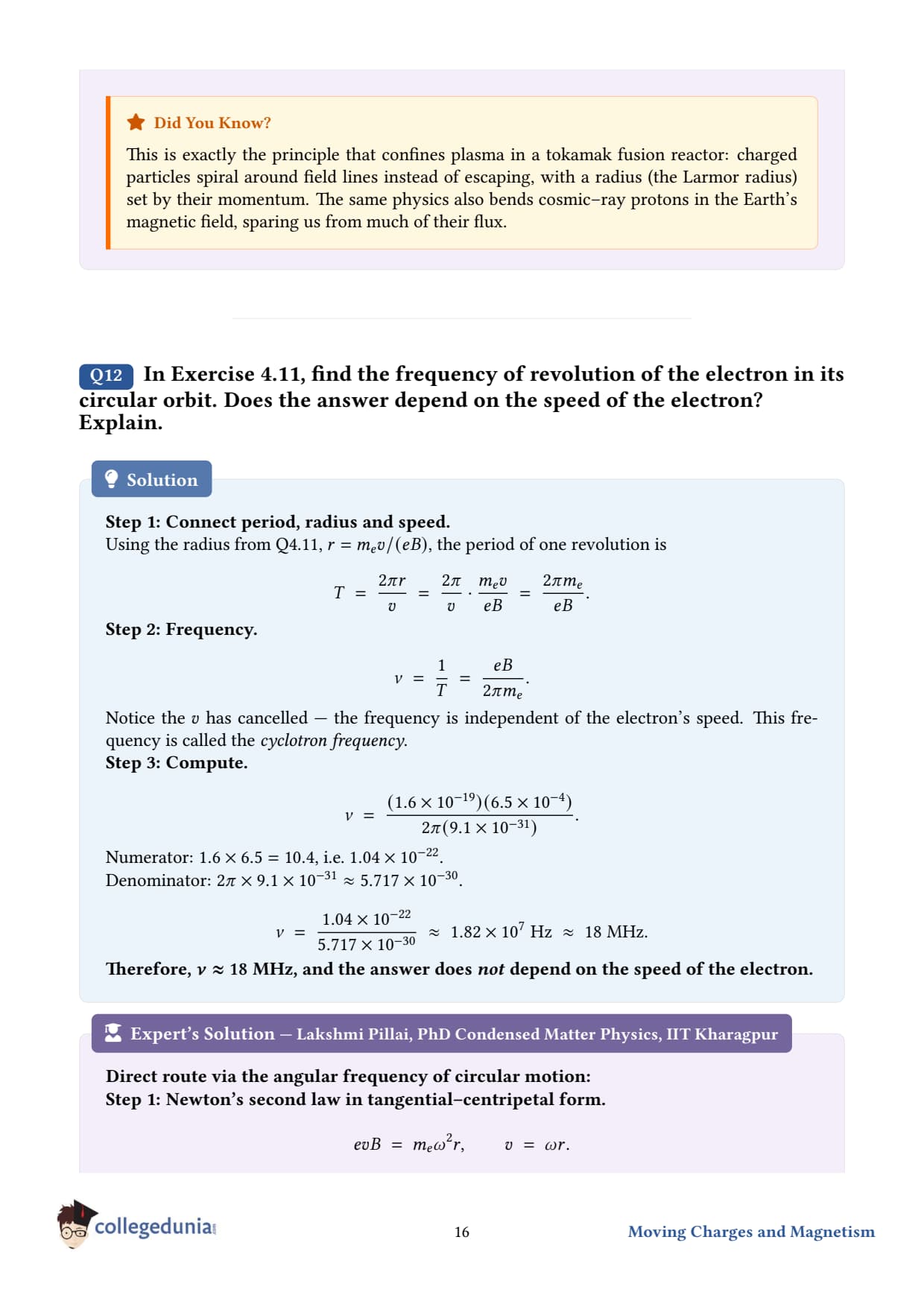
In Exercise 4.11 obtain the frequency of revolution of the electron in its circular orbit. Does the answer depend on the speed of the electron? Explain.
What the question is asking. Continuing from Q 4.11: the electron is going around a circle. How many revolutions per second? And does the frequency depend on how fast we shot the electron in?
Given. Same as Q 4.11: B = 6.5× 10⁻⁴T, e = 1.5× 10⁻¹⁹C, m = 9.1× 10⁻³¹ kg. And v = 4.8× 10⁶m/s (we may not even need this).
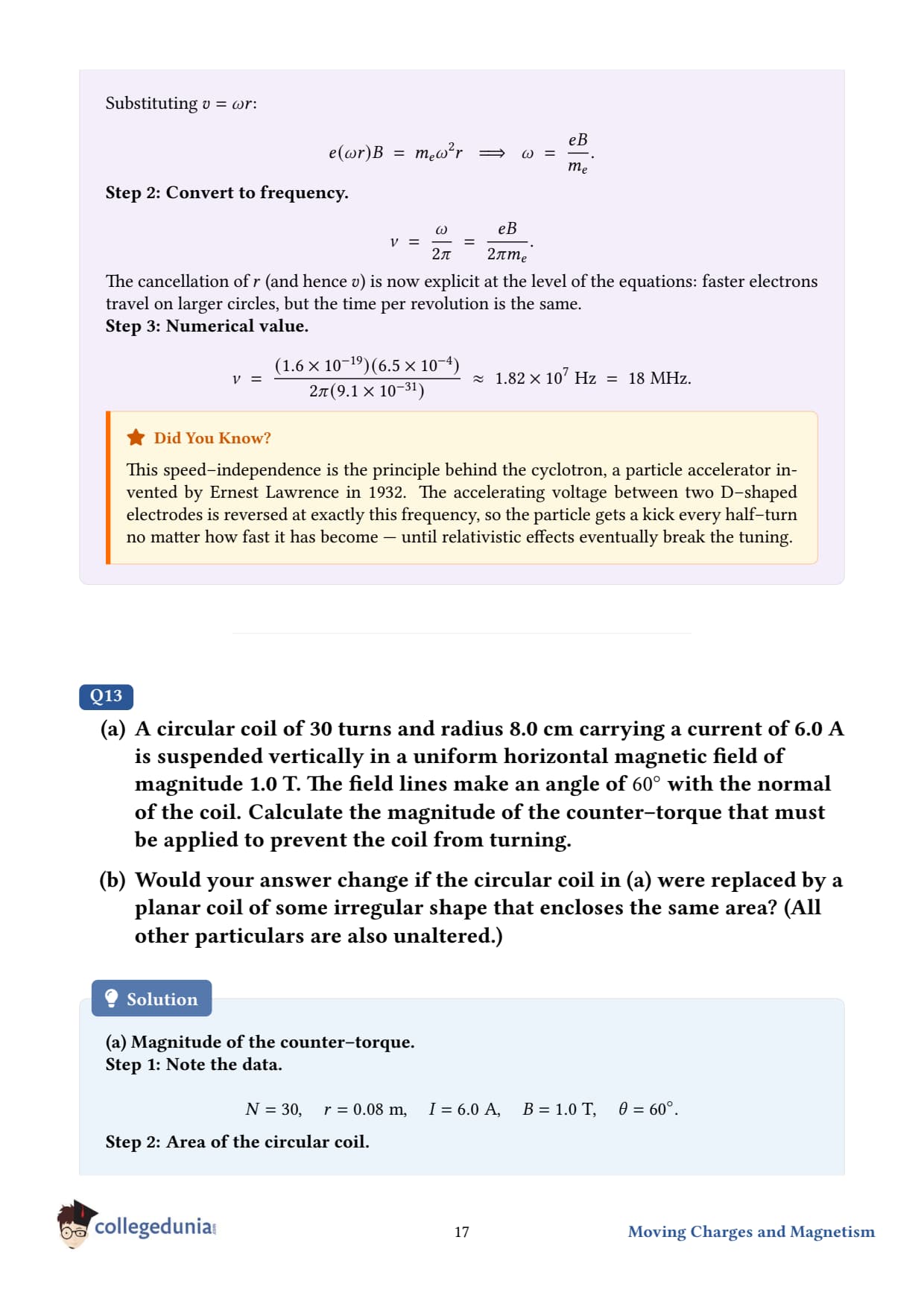
Concept used - cyclotron frequency. Period of revolution is "distance ÷ speed" = circumference ÷ speed: T = 2π rv. Substituting r = mv/(qB): T = 2πv·mvqB = 2π mqB. The v cancels! Frequency is: f = 1T = qB2π m. This is the famous cyclotron frequency. It depends only on q/m and B, not on speed.
Step 5 - answer the conceptual question. Looking at f = qB/2π m, notice that the speed v cancelled out. So the frequency does NOT depend on the electron's speed (so long as relativistic effects are negligible). Faster electrons trace larger circles but at the same number of revolutions per second.
Final answer.f ≈ 1.7× 10⁷ Hz; independent of speed.
PH
Prof. Hema Krishnan
Ph.D. High-Energy Physics, IISER Pune
Verified Expert
Why the speed cancels. A faster particle has higher momentum mv, giving a bigger radius r = mv/(qB). The circumference 2π r is also bigger by the same factor. But the speed itself is higher in the same proportion. So time-to-go-around (circumference ÷ speed) is unchanged. It's a beautiful balance - and it's what makes the cyclotron work.
The cyclotron. Ernest Lawrence built the first cyclotron in 1932 using exactly this insight: ions of a fixed q/m circle at a fixed frequency in a magnet, regardless of their speed. By applying an oscillating electric field at this same frequency across a gap, each crossing accelerates the ion further out, into ever-larger circles, until it has enough energy to be ejected. Won him the 1939 Nobel Prize.
Limits - when does speed start to matter? At relativistic speeds (v close to the speed of light), the mass effectively increases: m → γ m. The cyclotron frequency drops as energy rises. This is why high-energy accelerators use "synchrotrons" - devices that vary the field strength and oscillator frequency to compensate.
Sanity check. Modern radio operates between 105 and 1010 Hz. Our cyclotron frequency ∼ 17 MHz sits in the radio band - exactly the regime where solar electrons interacting with Earth's field generate natural "whistler" radio emissions detectable from the ground.
Q 4.13
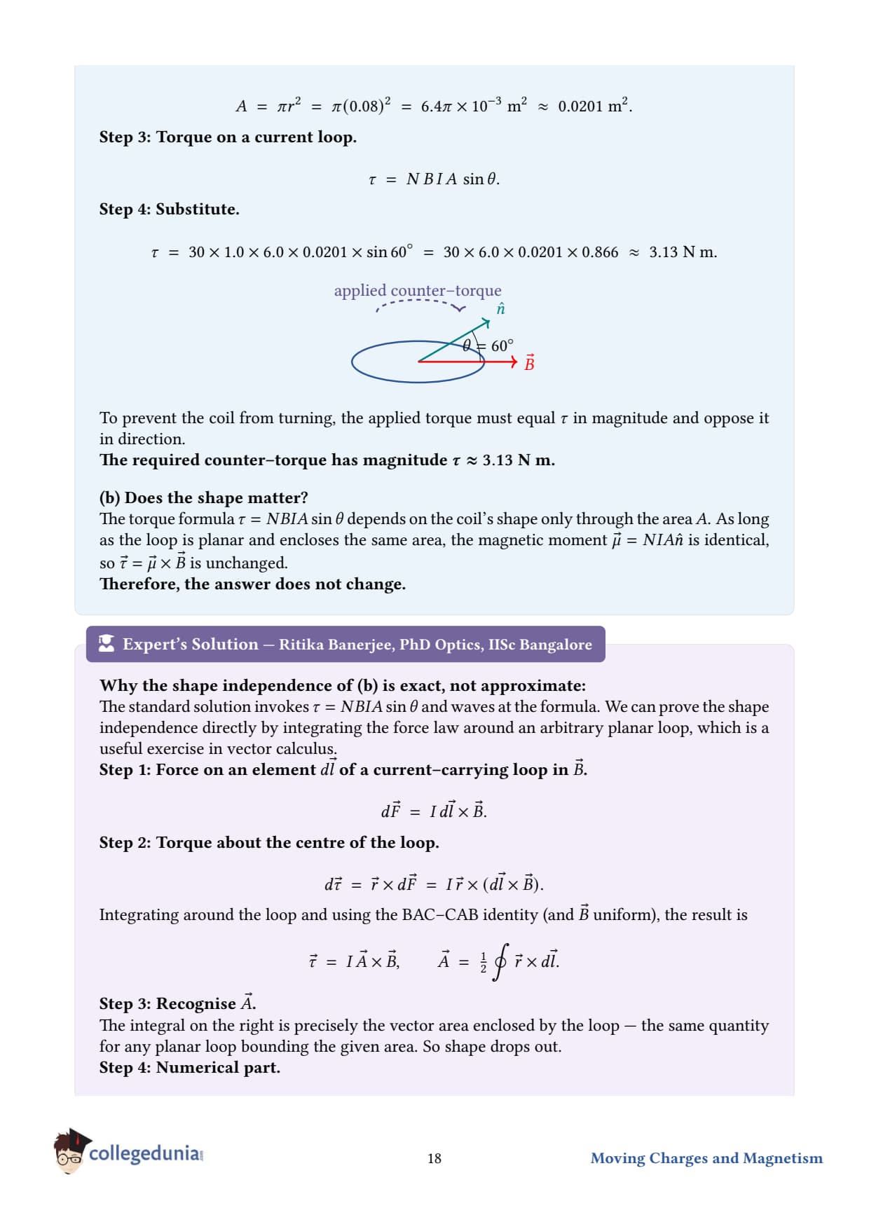
(a) A circular coil of 30 turns and radius 8.0 cm carrying a current of 6.0 A is suspended vertically in a uniform horizontal magnetic field of magnitude 1.0 T. The field lines make an angle of 60∘ with the normal of the coil. Calculate the magnitude of the counter torque that must be applied to prevent the coil from turning.
(b) Would your answer change, if the circular coil in (a) were replaced by a planar coil of some irregular shape that encloses the same area? (All other particulars are also unaltered.)
What the question is asking. A current loop sits in a magnetic field at a slant. The field tries to rotate the loop into alignment. To keep the loop fixed, we must apply an equal-and-opposite torque externally. We need its magnitude. Part (b) asks if the shape matters.
Given.
Number of turns, N = 30
Radius, r = 8.0 cm = 0.08 m
Current, I = 6.0 A
Field magnitude, B = 1.0 T
Angle between coil's normal and B, θ = 60∘
Concept used - torque on a current loop. τ = NIAB sinθ. The counter torque equals this magnitude in size but opposite in direction.
(a) Computing the torque.
Step 1 - area of the circular coil.A = π r2 = π (0.08)2 = π× 6.4× 10⁻³ ≈ 2.011× 10⁻² m2.
Step 2 - magnetic moment magnitude.m = NIA = (30)(6.0)(2.011× 10⁻²) ≈ 3.62 A m2.
Step 4 - counter torque has the same magnitude.counter ≈ 3.1 Nm.
(b) Does the shape matter?
The torque formula τ = NIABsinθ involves only the area enclosed by the loop - not its shape. So a circular loop and any irregular planar loop with the same area A (and the same N, I, B, and angle) feel the same torque.
Final answers.
(a) counter ≈ 3.1 Nm.
(b) No, the answer would not change - torque depends only on area, not on shape.
DS
Dr. Shalini Verma
Ph.D. Magnetism, IIT Guwahati
Verified Expert
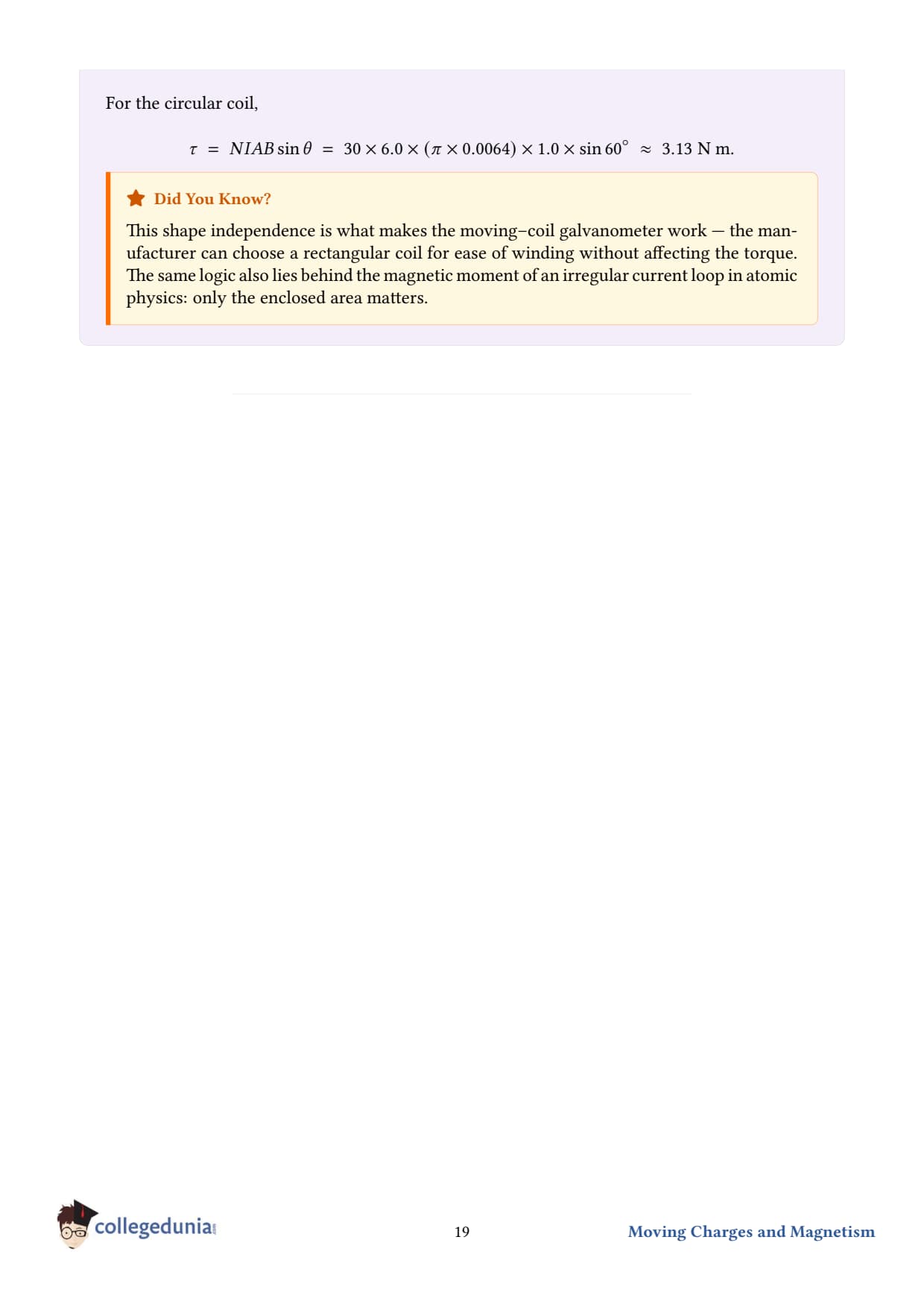
Why doesn't shape matter? Consider any planar loop carrying current I in field B. Slice it into thin strips parallel to one side. Each strip is a rectangle whose torque calculation is straightforward. Adding up all the rectangles' contributions, the cross-terms cancel and only the total enclosed area survives. The same conclusion follows from the more advanced result τ = m×B with m = IA - and A is the vector with magnitude equal to the loop's enclosed area, pointing along the normal (right-hand rule). The vector A depends only on the loop's projection, not on its zig-zags.
Counter torque vs. restoring torque. The field exerts a torque ON the coil that tries to rotate it. To hold the coil stationary, you must apply an EQUAL magnitude torque in the opposite direction. Net torque = zero ⇒ no angular acceleration.
Numerical sanity.τ ∼ 3 Nm is sizable - like the torque you exert turning a screwdriver. Strong magnets can grip current loops with quite formidable force. This is exactly how an electric motor delivers its torque.
Going further. If you wanted to find the WORK done in rotating the loop from 1 to 2: W = 12τ dθ = -mB(cos2 - cos1). The potential energy of the loop is U = -m·B = -mBcosθ, minimised when m∥B. This is why current loops naturally orient with their normals along the field - like compass needles aligning with Earth's field.
NCERT Solutions Class 12 Physics Chapter 4 Moving Charges and Magnetism FAQs
Ques. What are the main topics in ncert solutions class 12 physics chapter 4?
Ans. They cover Lorentz force, motion in a magnetic field, Biot-Savart law, Ampere's circuital law, solenoid and toroid, force between parallel currents, torque on a loop, and the moving coil galvanometer.
Ques. How do I write the direction of force in chapter 4 class 12 physics answers?
Ans. Use the right-hand rule for a moving charge: point fingers along v, curl toward B, and the thumb gives F = q v × B. For a wire use Fleming's left-hand rule with F = B I l sinθ. Always mark the direction on a labelled diagram to score the full mark.
Ques. Which exercises in chapter 4 class 12 physics carry the most marks?
Ans. Q 4.11 to 4.13 on torque, the galvanometer, and parallel currents are the 3 to 5-mark questions. The straight-wire and solenoid numericals (Q 4.6 to 4.10) are steady 3-markers. All are solved step by step on this page.
Ques. How is the magnetic field of a solenoid derived in ncert solutions class 12 physics ch 4?
Ans. Apply Ampere's law to a rectangular path with one side inside the solenoid (field along axis) and one outside (field zero). This gives B = μ₀nI, where n is turns per unit length.
Ques. What is the force between two parallel currents in ncert solutions for class 12 physics chapter 4?
Ans. Force per unit length F/L = μ₀I₁I₂/(2πd). Parallel currents attract; anti-parallel currents repel. This relation defines the ampere.
Ques. How many exercises are in physics chapter 4 class 12 ncert solutions?
Ans. The 2026-27 NCERT has 13 back exercises plus 11 in-text examples, all solved on this page, with the older deleted exercises worked too.
Ques. What is the weightage of class 12 chapter 4 physics ncert solutions in CBSE?
Ans. About 6 marks, usually one 3-mark derivation plus one 3-mark numerical. JEE Main draws 3 to 4 percent and NEET 1 to 2 questions a year.
Ques. What is Lorentz force?
Ans. Lorentz force is the total force on a charged particle: F = q(E + v × B). The magnetic part q v × B stays perpendicular to v, so it turns the motion but never changes the speed.








Comments