Physics Mentor, SRM Institute | Updated on - Jul 21, 2026
Electrostatic Potential and Capacitance is one of the highest-scoring chapters in Class 12 Physics. It carries strong weightage in CBSE boards, JEE Main, and NEET. This page hosts the full NCERT Solutions PDF, which you can read or download below.
CBSE Weightage:7 marks, usually one 5-mark derivation on capacitor energy or dielectric effect plus one short answer on equipotential surfaces.
JEE Main Weightage: 3 to 4 per cent, with two questions per shift on series-parallel combinations and energy stored.
NEET Weightage: 2 to 3 questions every year, mostly on a parallel plate capacitor with a dielectric.
Every solution here is checked by subject experts and mapped to the 2026-27 NCERT.
Exercise Breakdown for NCERT Solutions for Class 12 Physics Chapter 2
The chapter has 36 back exercises plus 11 in-text examples across 15 sub-topics. Exercises 2.1 to 2.11 are conceptual; from 2.12 onward most are multi-step numericals worth 3 to 5 marks.
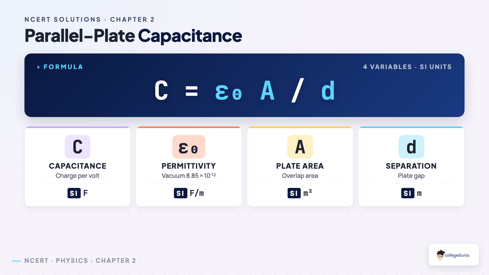
Parallel-plate capacitance - geometry and constants.
Capacitance Weightage Compared Across Class 12 Physics Chapters
The table below shows how Chapter 2 weightage compares with every other Class 12 Physics chapter. Marks are CBSE board averages. Chapter 2 ties with Chapters 3 and 9 for the top weightage.
Chapter
Topic
Avg CBSE Marks
Ch 1
Electric Charges and Fields
6 marks
Ch 2
Electrostatic Potential and Capacitance
7 marks
Ch 3
Current Electricity
7 marks
Ch 4
Moving Charges and Magnetism
6 marks
Ch 5
Magnetism and Matter
3 marks
Ch 6
Electromagnetic Induction
5 marks
Ch 7
Alternating Current
6 marks
Ch 8
Electromagnetic Waves
2 marks
Ch 9
Ray Optics and Optical Instruments
7 marks
Ch 10
Wave Optics
5 marks
Ch 11
Dual Nature of Radiation and Matter
4 marks
Ch 12
Atoms
3 marks
Ch 13
Nuclei
3 marks
Ch 14
Semiconductor Electronics
6 marks
Electrostatic Potential and Capacitance Previous Year Questions Weightage (2021 to 2026)
The table below maps every CBSE, JEE Main, and NEET appearance of Chapter 2 topics over six sessions. Capacitor energy and dielectric effects come back almost every board year.
Year
CBSE Board
JEE Main
NEET
2026
Dielectric effect on capacitance (5 marks)
Series-parallel combination (4 marks)
Capacitance and energy stored in a capacitor (3 questions)
2025
Energy stored in a capacitor (3 marks)
Potential due to dipole (4 marks)
Capacitance with dielectric (4 marks)
2024
Parallel plate capacitor derivation (5 marks)
Equipotential surfaces MCQ
Energy stored MCQ
2023
Equipotential surfaces properties (3 marks)
Two-capacitor connection problem
Potential of a system of charges
2022
Capacitor with mixed dielectric (5 marks)
Energy is lost on the connection
Spherical capacitor
2021
-
Variable plate-separation problem
Series combination
How Collegedunia's NCERT Solutions for Class 12 Physics Chapter 2 Help You
These solutions match the 2026-27 syllabus, with every step written the way CBSE marks it.
Full marking-scheme steps: students get the same answer CBSE gives full marks to, with no skipped step.
Labelled diagrams: every capacitor, equipotential surface, and dielectric problem has a sketch students can copy.
Expert-checked formulas: each formula is verified against the official NCERT Part 1 print.
Common Mistakes Students Make in Chapter 2 Physics Class 12 NCERT Solutions
These mistakes turn up in CBSE scripts every year, and each one can turn a 5-marker into a 2 or 3.
Mistake 1: Treating potential V and potential energy U as the same. V is per unit charge (volt); U is the full work done (joule).
Mistake 2: Forgetting that dielectric insertion differs with the battery on or off. Battery on: charge changes, V is constant. Battery off: charge stays, V changes.
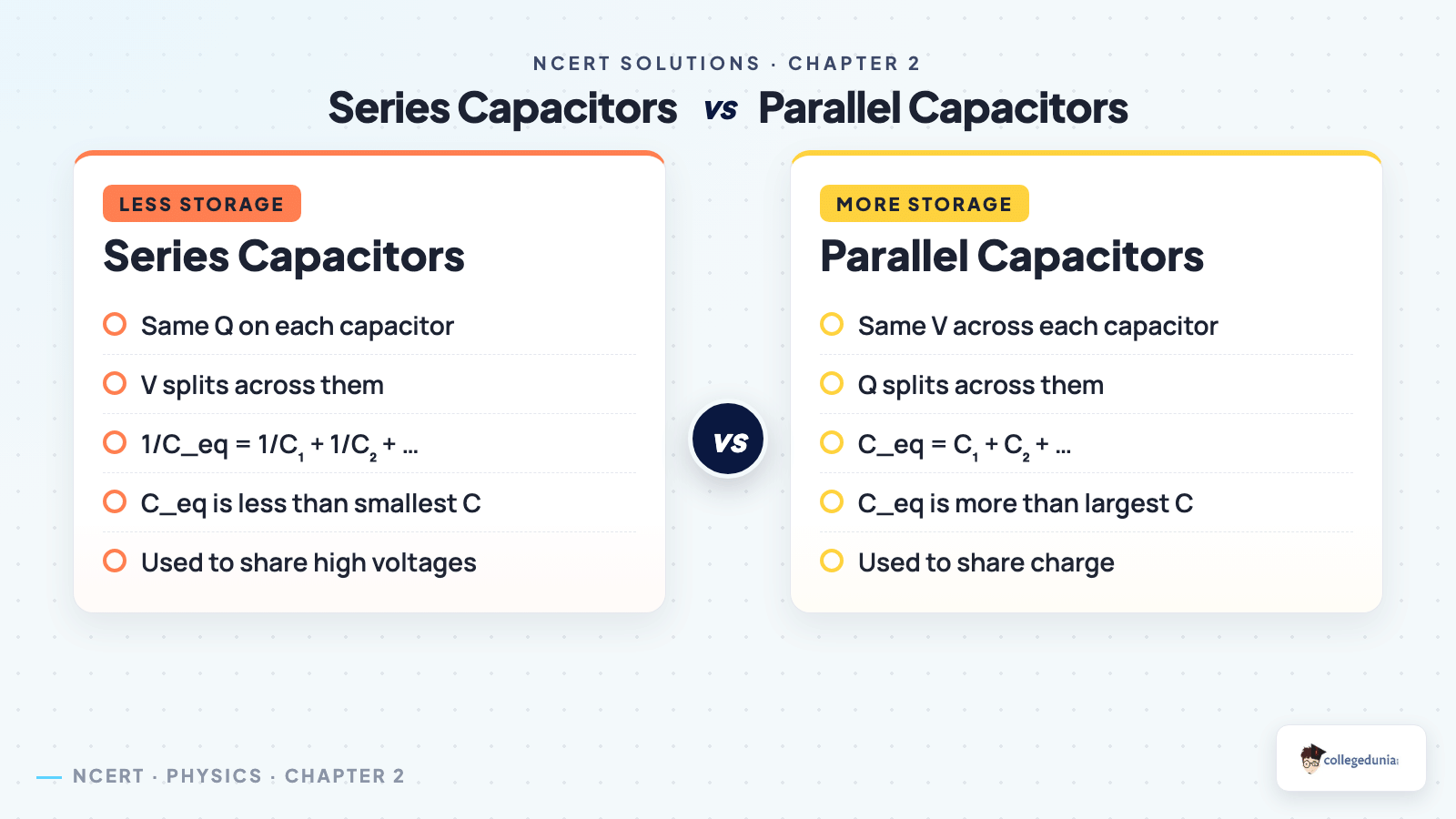
Mistake 3: Swapping the series and parallel formulas. Series: 1/C = sum of 1/C_i, same charge. Parallel: C = sum of C_i, same voltage.
Mistake 4: Writing energy as CV instead of half CV squared. Dropping the half is a sure 2-mark loss.
Important Derivations Index for Chapter 2 with Year-Wise Appearance
Six derivations carry most of the marks in Chapter 2. The index below maps each one to its CBSE marks and where it last appeared.
Derivation
Marks (CBSE)
Last Major Appearance
Potential due to a point charge
2
CBSE 2025
Potential due to an electric dipole on the axial line
3
JEE Main 2025 Jan Shift 2
Potential due to a dipole on the equatorial line
3
CBSE 2023
Parallel plate capacitor: capacitance formula
5
CBSE 2024 Set 55/1/1
Effect of dielectric on a parallel plate capacitor
5
CBSE 2026, NEET 2025
Energy stored in a charged capacitor
3
CBSE 2025, JEE Main 2024
Quick-Reference Formula Table for Physics Ch 2 Class 12 NCERT Solutions
The 12 formulas below cover almost every Chapter 2 numerical. Most 3-mark and 5-mark sums reduce to one of them.
Concept
Formula
SI Unit
Electric potential (point charge)
V = k q / r
volt (V)
Potential difference
V_AB = V_A minus V_B = W_AB / q
volt
Potential due to a dipole (axial)
V = k p cos theta / r squared
volt
Potential due to a dipole (equatorial)
V = 0
volt
Potential energy of two charges
U = k q1 q2 / r
joule
Capacitance
C = Q / V
farad (F)
Capacitance of a parallel plate capacitor
C = epsilon_0 A / d
farad
Capacitance with a dielectric
C = K epsilon_0 A / d
farad
Capacitors in series
1/C = 1/C1 + 1/C2 + ...
per farad
Capacitors in parallel
C = C1 + C2 + ...
farad
Energy stored in a capacitor
U = half C V squared = half Q V = Q squared / (2 C)
All NCERT Solutions for Class 12 Physics Chapter 2 Electrostatic Potential and Capacitance with Step-by-Step Solutions
Every question of NCERT Class 12 Physics Electrostatic Potential and Capacitance is listed below with its full Solution and Expert Solution hidden inside collapsible tabs. Click Check Solution to reveal the step-by-step working; click Expert Solution for the expanded explanation.
Q 2.1
Two charges 510-8C and -310-8C are located 16 cm apart. At what point(s) on the line joining the two charges is the electric potential zero? Take the potential at infinity to be zero.
What the question is asking. We have two point charges of opposite sign on a straight line, 16 cm apart. We need every point on that line where the electric potentials from the two charges exactly cancel - i.e., where the total potential is zero (with infinity as the reference).
Given.
q1 = +510-8C at point A.
q2 = -310-8C at point B.
Separation AB = 16 cm = 0.16 m.
Concept used - potential due to a point charge. The electrostatic potential at a distance r from a point charge q (with V∞=0) is V = 14π0qr. Potential is a scalar - it adds with signs, not as vectors. The sign of q is carried into the answer.
Step 1 - set up a coordinate. Let A be at x=0 and B be at x=16 cm. Let P at coordinate x on the line AB be the point where V=0. We must consider three regions: (i) between A and B (0 < x < 16), (ii) right of B (x > 16), and (iii) left of A (x < 0).
Step 2 - write the total potential. Let distances be r1 = |x - 0| and r2 = |x - 16| (in cm). Then VP = kq1r1 + kq2r2 = k(q1r1 + q2r2). Setting VP = 0: q1r1 + q2r2 = 0 q1r1 = -q2r2.
Step 3 - case A: point P lies between A and B. Then r1 = x and r2 = 16 - x, both positive. The equation becomes 510-8x = 310-816 - x. Cross-multiply: 5(16 - x) = 3x 80 - 5x = 3x 8x = 80 x = 10 cm. So one zero-potential point lies 10 cm from A equivalently 6 cm from B, between the two charges.
Step 4 - case B: point P lies outside, on the side of -310-8C (i.e., x > 16). Now r1 = x and r2 = x - 16. The equation 510-8x = 310-8x - 16 gives 5(x - 16) = 3x 5x - 80 = 3x 2x = 80 x = 40 cm. So a second zero-potential point lies 40 cm from A - i.e., 24 cm beyond B on the far side.
Step 5 - case C: P to the left of A (x < 0). Then r1 = -x, r2 = 16 - x. The equation q1/r1 = -q2/r2 gives 510-8-x = 310-816 - x. But the left side is positive only when x < 0, and we get 5(16-x) = -3x, i.e., 80 - 5x = -3x, so 2x = 80, x = 40 cm - which contradicts x < 0. No solution in this region. (Physically: on the far side of the larger positive charge, the positive potential from it always exceeds the negative potential from the smaller, more distant negative charge.)
Final answer. Zero potential at 10 cm from A (between the charges) and at 40 cm from A (beyond B).
DR
Dr. Rajesh Kumar
Ph.D. Physics, IIT Delhi
Verified Expert
Why exactly two zero-potential points. When the two charges have opposite signs and unequal magnitudes, the locus V = 0 on the line joining them always has two points: one in the interior (where the potentials cancel because of opposite signs) and one exterior (on the side of the smaller-magnitude charge, where the smaller-but-closer charge's potential balances the larger-but-farther one). If the charges were equal and opposite, the interior zero is the midpoint and there is no exterior zero - the exterior point recedes to infinity.
Off the line - the zero-potential surface. If you allow points off the line joining A and B, the locus V=0 is a sphere (the "Apollonius sphere"). For q1 and q2 of opposite signs and |q1| ≠ |q2|, the set of all points where V1 + V2 = 0 satisfies |q1|/r1 = |q2|/r2, i.e., r1/r2 = |q1|/|q2| = 5/3 = constant. This is the geometric definition of a sphere in 3D (Apollonius). The two points we found on the line are the two points where this sphere intersects the line AB.
Common mistake - sign of the distance. When the test point lies outside the segment, students sometimes set r2 = 16 - x with x > 16, which gives a negative r2. But r in the potential formula is always a positive distance. Always write r = |x - x0| explicitly.
Quick sanity check. At x = 10 cm, the potential from q1 is V1 = 9109510-8/0.10 = 4500 V. The potential from q2 is V2 = 9109-310-8/0.06 = -4500 V. Sum: zero.
Did you know? Even though the potential is zero at these two points, the electric field is generally not zero there. V = 0 means no work is needed to bring a charge from infinity to that point - but the field can still push the charge sideways at the point.
Q 2.2
A regular hexagon of side 10 cm has a charge 5 at each of its vertices. Calculate the potential at the centre of the hexagon.
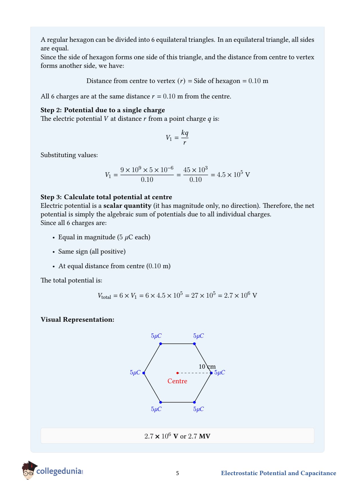
What the question is asking. Six identical positive charges sit at the six corners of a regular hexagon of side 10 cm. Find the electric potential at the centre of the hexagon.
Given.
Side of hexagon, a = 10 cm = 0.10 m.
Charge at each vertex, q = 5 = 510-6C.
Number of vertices, N = 6.
Concept used.
For a regular hexagon, the centre is equidistant from all six vertices. In fact, the distance from centre to vertex equals the side length: r = a = 0.10 m. (A regular hexagon is made of 6 equilateral triangles meeting at the centre - each triangle has all sides equal to a.)
Potential is a scalar: it adds algebraically. Six identical charges at equal distance contribute equally.
Step 1 - distance from centre to each vertex. For a regular hexagon of side a: r = a = 0.10 m.
Step 2 - potential from one charge at the centre. V1 = 14π0qr = kqr.
Step 3 - total potential at the centre. Because all six contributions are equal and have the same sign, V = 6 V1 = 6 kqr.
Final answer.V = 2.7106V = 2.7 MV. This is a large potential - about a million times the voltage of a household battery. It would not occur in practice unless the charges were held in place by an insulating frame, because mutual repulsion would otherwise blow the configuration apart.
DA
Dr. Anita Sharma
Ph.D. Physics, University of Delhi
Verified Expert
Why r = a for a hexagon - and not for other polygons. A regular n-gon of side a has the circumradius (centre-to-vertex distance) R = a2sin(π/n). For n=6, sinπ/6 = 1/2, so R = a/2· 1/2 = a. This is unique to the hexagon - for a square n=4R = a/√2; for a pentagon n=5R ≈ 0.85 a; for a triangle n=3R = a/√3.
Electric field at the centre is zero. Even though the potential is large, the field cancels by symmetry. Each charge pulls in a direction 2π/6 = 60∘ from its neighbour, so the six field vectors sum to zero. This illustrates that V and E are independent: high V does not necessarily mean strong E.
Generalisation - n charges at the vertices of a regular n-gon. Vcentre = nkqR, Ecentre = 0. Same logic - n equal scalar contributions add; n vectors at equal angular spacing cancel.
Sanity check. A single 5 charge at 10 cm gives kq/r = 9109510-6/0.10 = 4.5105V. Six of them gives 6× 4.5105 = 2.7106V.
Q 2.3
Two charges 2 and -2 are placed at points A and B 6 cm apart.
(a) Identify an equipotential surface of the system.
(b) What is the direction of the electric field at every point on this surface?
What the question is asking. Two equal-and-opposite charges form an electric dipole. We need to find a surface on which every point has the same potential, and figure out which way the field points on that surface.
Given.
qA = +2 at A.
qB = -2 at B.
Separation AB = 6 cm.
Concept used. An equipotential surface is one on which the potential is constant. For a single point charge, equipotential surfaces are concentric spheres centred on the charge. For two charges, you must add the potentials and look for the locus of constant total V.
Step 1 - locate the obvious equipotential. Consider any point P that is equidistant from A and B: rA = rB = r. Then VP = kqArA + kqBrB = k(+2 )r + k(-2 )r = 0. So every point equidistant from A and B has V = 0 - they all share the same potential.
Step 2 - what surface is "equidistant from two points"? The set of points in 3D equidistant from two given points is the perpendicular bisector plane of the line segment joining them. For our dipole, that's the plane perpendicular to AB and passing through its midpoint.
(a) Equipotential surface. The perpendicular bisector plane of AB - the plane normal to AB, passing through its midpoint - is the equipotential surface V = 0.
(b) Direction of the field on this surface. On an equipotential surface, the electric field is always perpendicular to the surface. Reason: if there were any component of E parallel to the surface, moving a test charge along that direction would do nonzero work - but V is constant along the surface, so work = q Δ V = 0. The only way to satisfy this for any direction tangent to the surface is for E to have no tangential component, i.e., E ⊥ surface.
Since our surface is perpendicular to AB, the perpendicular to the surface is parallel to AB. So at every point on this equipotential surface, E points along the line AB, from the positive charge (A) toward the negative charge (B).
Final answer.
(a) Equipotential surface: the perpendicular bisector plane of AB (containing the midpoint and normal to AB). On this plane, V = 0.
(b) The electric field at every point on this surface is perpendicular to the surface, hence parallel to AB. It points from the positive charge +2 toward the negative charge -2 (i.e., from A toward B).
DS
Dr. Suresh Iyer
Ph.D. Theoretical Physics, TIFR Mumbai
Verified Expert
Why E is always perpendicular to equipotential surfaces. This is the most useful single fact about equipotentials. Combined with E = -∇ V, it tells you: field lines and equipotential surfaces form a grid (orthogonal mesh). Sketch one, and you immediately know the other.
Other equipotentials of a dipole. The full equipotential structure of a dipole is more complex than just the bisector plane:
Far from the dipole, equipotentials are approximately the dipole-field equipotentials, which look like figure-of-eight cross-sections in 2D, or "apple-shaped" surfaces in 3D, with V ∝ pcosθ/r2.
Near each individual charge, equipotentials are nearly spherical, centred on that charge.
The V = 0 surface (the perpendicular bisector) is the dividing surface between the two regions of opposite sign.
Why V=0 doesn't mean E = 0. A common confusion. The perpendicular bisector plane has V = 0, but E is large and nonzero there. Potential and field measure different things - V measures work-per-charge to bring something there from infinity; E measures local force-per-charge. Don't conflate them.
Why field points from + to - on the bisector. Decompose the field at a point P on the bisector. The contribution from +q at A points away from A (i.e., outward from A); from -q at B points toward B (i.e., inward to B). The components perpendicular to AB cancel (by symmetry of the equal distances). The components along AB add - both point in the A → B direction. So net E at P is along AB, pointing from + to -.
Q 2.4
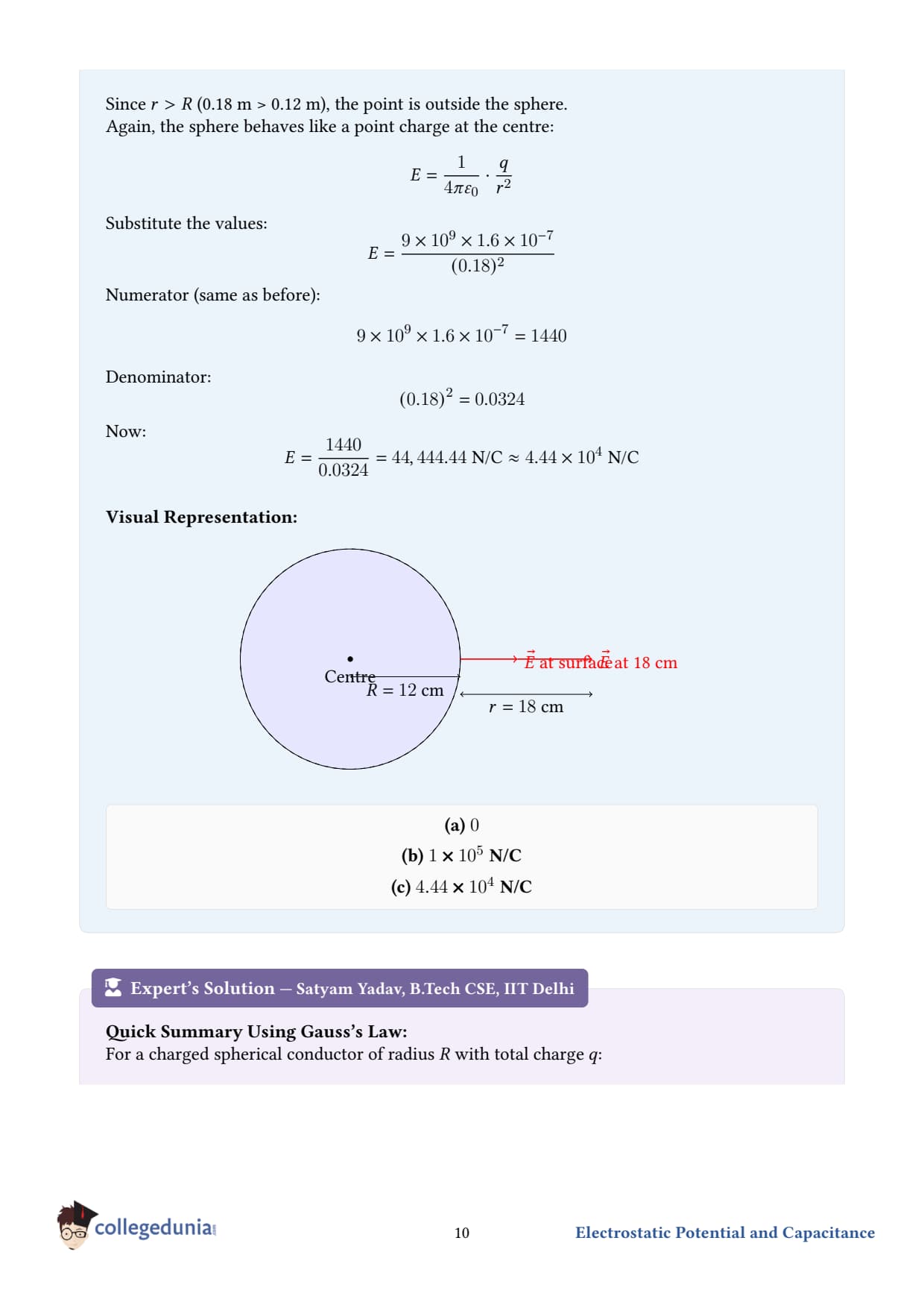
A spherical conductor of radius 12 cm has a charge of 1.610-7C distributed uniformly on its surface. What is the electric field
(a) inside the sphere,
(b) just outside the sphere,
(c) at a point 18 cm from the centre of the sphere?
Given.
Radius of conductor, R = 12 cm = 0.12 m.
Total charge, Q = 1.610-7C, uniformly distributed on the surface.
Coulomb constant, k = 9109N m2 C-2.
Concept used - Gauss's law for a spherically symmetric conductor.
Inside a charged conductor (in electrostatic equilibrium): E = 0 - because any internal field would push the free electrons until they redistribute and kill it.
Outside, the conductor looks (from the field's point of view) exactly like a point charge Q sitting at its centre. So Eoutside(r) = 14π0Qr2r ≥ R.
(a) Electric field inside the sphere.
The interior of a conductor in electrostatic equilibrium has zero electric field everywhere: Einside = 0.
(b) Electric field just outside the sphere. Set r = R = 0.12 m.
Step 1 - apply the formula.E = kQR2 = (9109)(1.610-7)(0.12)2.
Step 2 - compute the numerator. kQ = (9109)(1.610-7) = 14.4102 = 1.44103.
Why field is zero inside a conductor. Free electrons in a metal redistribute almost instantaneously in ∼ 10-19s until any internal electric field is exactly cancelled. At equilibrium, Einside=0; the field discontinuously jumps from 0 just inside the surface to σ/0 just outside. This jump is the source of the surface-charge density.
Surface charge density. σ = Q4π R2 = 1.610-74π(0.12)2 ≈ 8.8410-7C/m2. And indeed, σ/0 = 8.8410-7/8.85410-12 ≈ 1.0105N/C, which matches our answer in (b).
Inverse-square sanity check on (c). Moving from r = 12 cmwhere E = 105 to r = 18 cm is a factor-of-1.5 increase in radius. So E should drop by (1.5)2 = 2.25. Predicted: 105/2.25 = 4.44104N/C.
Common mistake - treating it as a uniform volume charge. For a conductor, charge sits on the surface only, not in the bulk. The formulas Einside=0, Eoutside=kQ/r2 apply specifically to surface-charge conductors. For a non-conducting (insulating) sphere with uniform volume charge, the inside field would grow linearly with rEin = kQr/R3, not be zero.
Application - Van de Graaff generator. A hollow conducting sphere can accumulate enormous surface charge (millions of volts) without any electric field inside it - which is why scientific instruments are often placed inside Faraday cages. The 1929 Van de Graaff generator at MIT reached 10 million volts using a 5-metre sphere.
Q 2.5
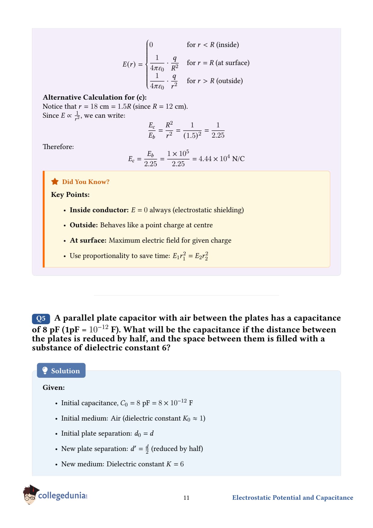
A parallel plate capacitor with air between the plates has a capacitance of 8 pF1 pF = 10-12F. What will be the capacitance if the distance between the plates is reduced by half, and the space between them is filled with a substance of dielectric constant 6?
New medium: dielectric of constant K = 6 (replaces air).
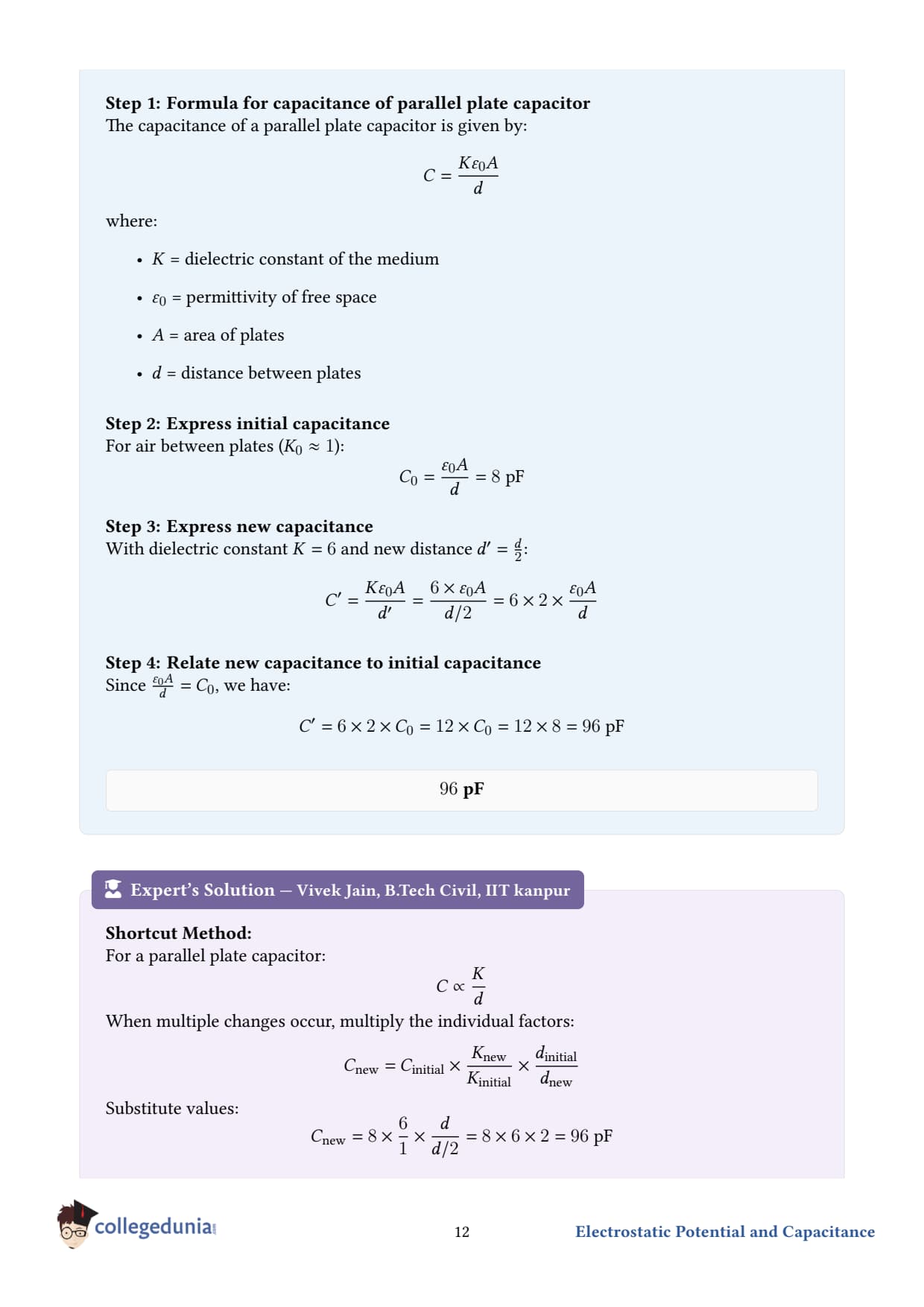
Concept used - capacitance of a parallel-plate capacitor.C = K0Ad, where A is the plate area, d is the gap, and K is the dielectric constant of the material between the plates K = 1 for vacuum or air. The capacitance:
increases if A increases (more space for charge);
increases if d decreases (closer plates → stronger electric coupling);
increases if K increases (dielectric "screens" the field, allowing more charge for the same voltage).
Step 1 - write the original capacitance. C1 = 0Ad = 8 pF. Note Kair = 1, so it doesn't appear explicitly.
Step 2 - write the new capacitance. With d → d/2 and K = 6: C2 = K0Ad/2 = 6 0A · 2d = 12 0Ad.
Final answer. C2 = 96 pF. The capacitance has gone up by a factor of 12 - a combined gain of × 2 from halving the gap and × 6 from the dielectric.
DV
Dr. Vikram Rao
Ph.D. Condensed Matter Physics, IIT Bombay
Verified Expert
The factor-of-12 logic in one breath.C2C1 = K2/d2K1/d1 = 6/(d/2)1/d = 12/d1/d = 12. Use this ratio shortcut whenever a problem changes K, d, or A of a capacitor - you never need to know 0 or A numerically.
Why dielectric increases capacitance. When a dielectric (insulator) sits in an electric field, its molecules polarise: small internal dipoles align, with bound positive charges facing the negative plate and bound negative charges facing the positive plate. These bound charges partially neutralise the field of the free charges on the plates, so the net field between the plates drops by a factor K. For the same charge on the plates, the voltage V = E· d drops by K - and C = Q/V goes up by K. Hence Cdielectric = K Cair.
Limits of "halve the gap" in practice. Pushing plates closer increases capacitance, but the dielectric must withstand the stronger field E = V/d. Each material has a dielectric breakdown threshold - typically ∼ 3 kV/mm for air, ∼ 100 kV/mm for solid insulators like mica. Past this, the dielectric sparks and the capacitor fails.
Common mistake. Some students compute C = K0A/d but plug in d as the new d/2 and K only on the right side - getting half the right answer. Be careful: each factor (K, A, 1/d) multiplies the original C.
Q 2.6
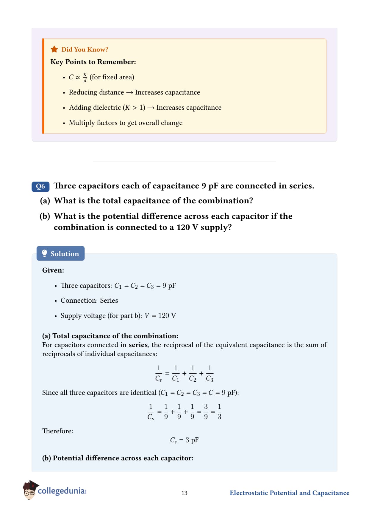
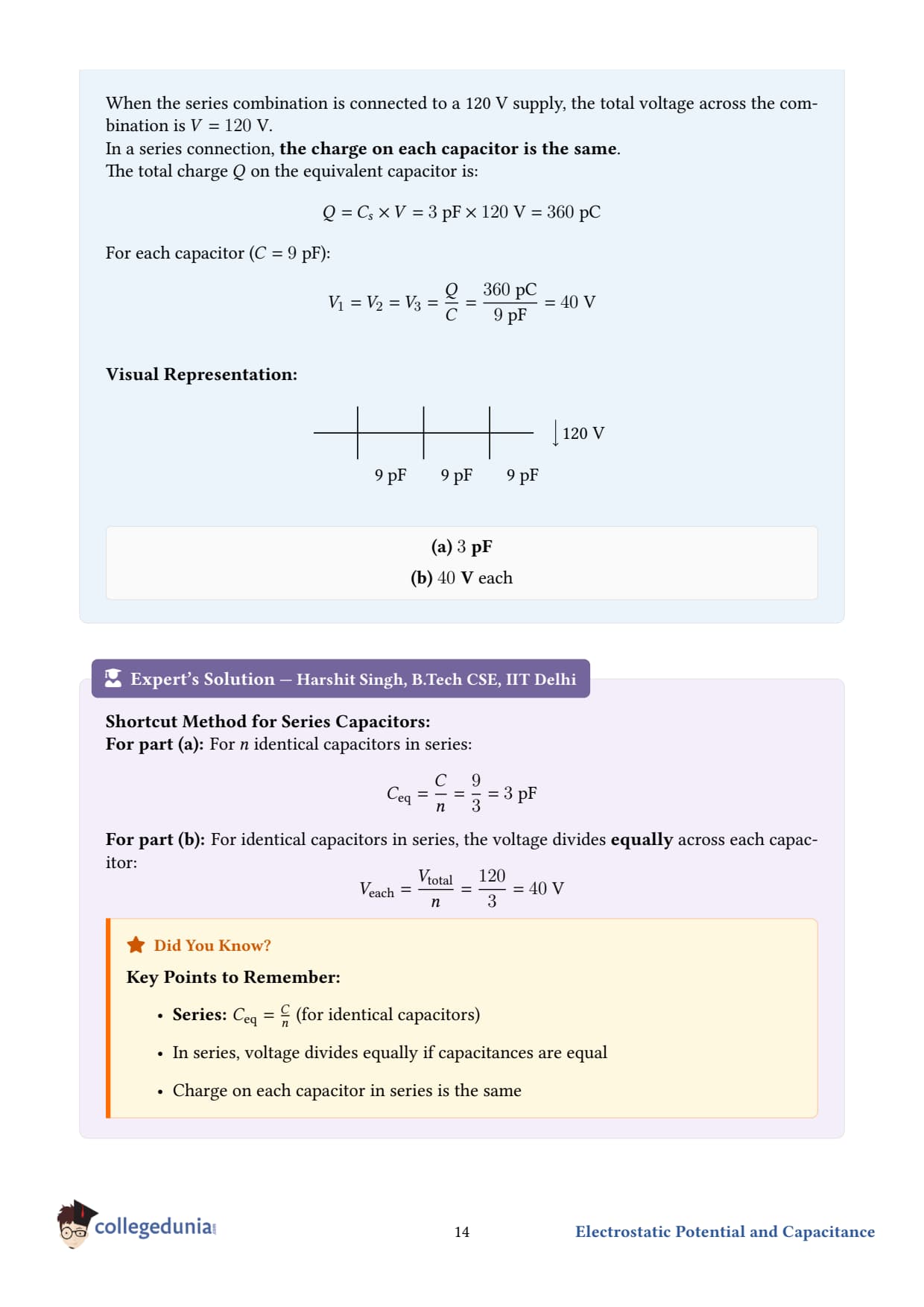
Three capacitors each of capacitance 9 pF are connected in series.
(a) What is the total capacitance of the combination?
(b) What is the potential difference across each capacitor if the combination is connected to a 120 V supply?
Given.
Three identical capacitors, each C = 9 pF = 910-12F, in series.
Supply voltage V = 120 V.
Concept used - capacitors in series.1Ceq = 1C1 + 1C2 + 1C3 + … In series, the same charge Q sits on every capacitor (charge cannot accumulate on the isolated central plates). The voltage divides between them inversely as their capacitance.
(a) Equivalent capacitance.
Step 1 - three equal capacitors in series.1Ceq = 1C + 1C + 1C = 3C.
Step 2 - invert. Ceq = C3 = 9 pF3 = 3 pF.
(b) Potential difference across each capacitor.
Step 1 - charge on the equivalent capacitor. When 120 V is applied, Q = CeqV = (310-12)(120) = 36010-12C = 3.610-10C. This same charge sits on every one of the three series capacitors.
Step 2 - voltage across each individual capacitor. Veach = QC = 3.610-10910-12 = 40 V.
Sanity check. The three voltages should add to the supply: 40 + 40 + 40 = 120 V.
Final answers.
(a) Ceq = 3 pF.
(b) Veach = 40 V across each capacitor.
DK
Dr. Kavita Joshi
Ph.D. Electrostatics, IIT Madras
Verified Expert
Series shortcut for n equal capacitors. Ceq = Cn, Veach = Vn. Memorise this - it's the most common configuration in JEE/NEET. Same goes for n equal resistors in parallel.
Intuition - why series decreases capacitance. Think of capacitance as "ability to store charge per unit voltage." In series, the charge must squeeze through three capacitors in turn - but more importantly, the same charge produces a separate voltage drop across each one. The total voltage required to push a given charge through is 3 × what it would be for one capacitor, so C = Q/V is one-third.
Parallel comparison. The same three 9 pF capacitors in parallel would give Ceq = 27 pF - nine times the series value. Parallel always increases capacitance (adds areas; effectively a bigger plate); series always decreases it.
Common mistake. Students sometimes use the series formula and forget to invert at the end. Always check: in series, Ceq must be less than the smallest individual capacitor. If your answer says otherwise, you forgot to take the reciprocal.
Energy. Total stored energy = 12 Ceq V2 = 12 310-12(120)2 = 2.1610-8J. Each capacitor stores one-third of this because each has the same Q and the same C, hence the same 12 Q2/C.
Q 2.7
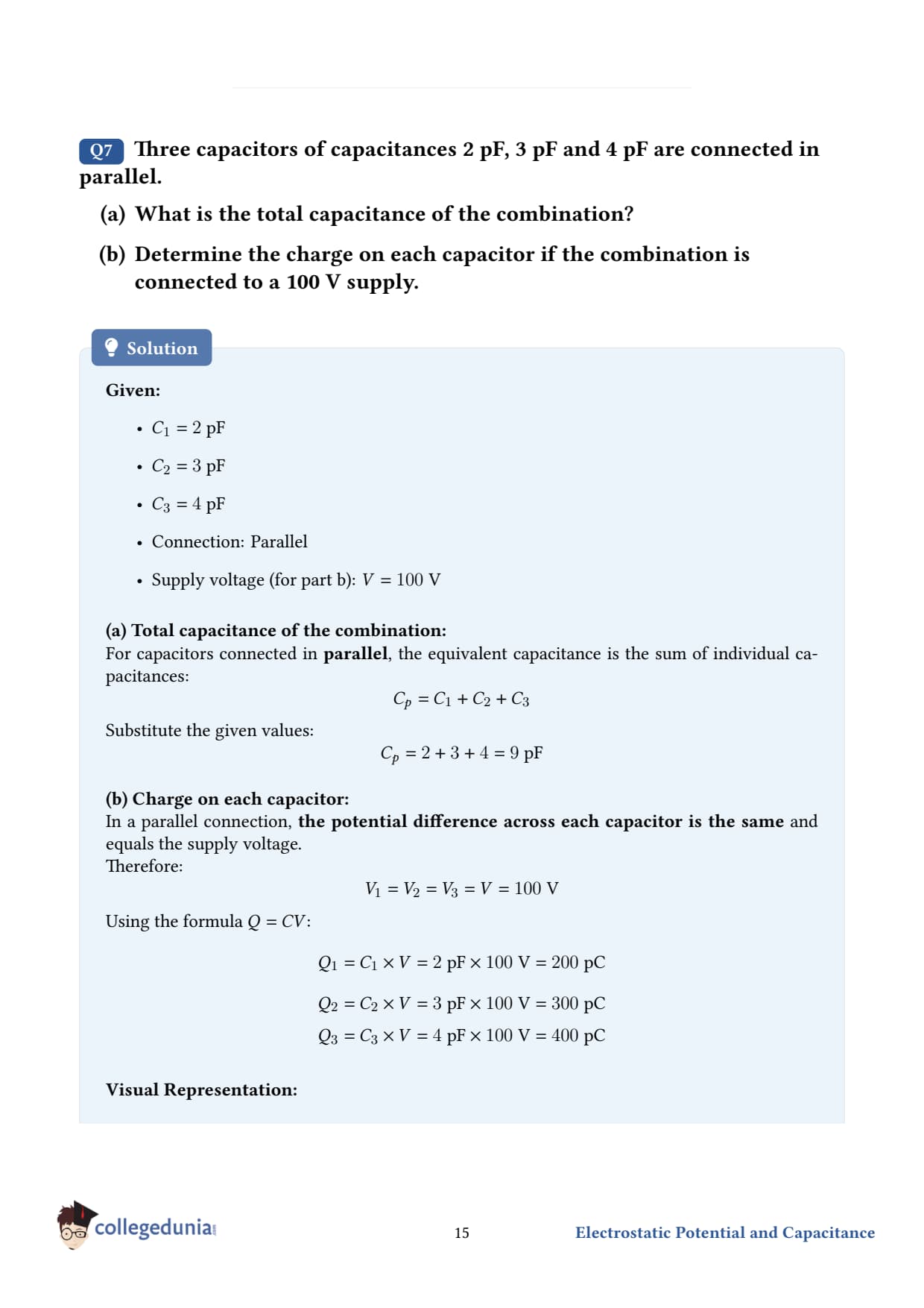
Three capacitors of capacitances 2 pF, 3 pF and 4 pF are connected in parallel.
(a) What is the total capacitance of the combination?
(b) Determine the charge on each capacitor if the combination is connected to a 100 V supply.
Given.
C1 = 2 pF, C2 = 3 pF, C3 = 4 pF, in parallel.
Supply voltage V = 100 V.
Concept used - capacitors in parallel. Ceq = C1 + C2 + C3 + … In parallel, every capacitor sits across the same voltage V. Each acquires a charge Qi = CiV, and the total charge from the supply is the sum of the individual charges.
Why parallel adds capacitances. Geometrically: putting two capacitors in parallel is equivalent to making one bigger capacitor whose plate area equals the sum of the two individual areas. Since C ∝ A, capacitances add. Electrically: same voltage across each, charges add - total charge for a given voltage goes up, so capacitance goes up.
Voltage stays the same across each capacitor in parallel. This is the key constraint to remember. In parallel: V shared, Q distributed. In series: Q shared, V distributed. Confusing these two is one of the most common errors in capacitor problems.
Why bigger capacitor gets more charge in parallel. Qi = CiV. With V fixed, Q scales linearly with C. The biggest capacitor 4 pF carries the most charge 400 pC; the smallest 2 pF carries the least 200 pC.
Energy comparison. Total energy stored: U = 12 Ceq V2 = 12 (910-12)(100)2 = 4.510-8J. This is distributed in proportion to capacitance: U1 = 12 C1 V2 = 10-8J, etc.
Common mistake. Some students compute the charge using CeqV and then divide it equally among the three capacitors. That's wrong - the charges are not equal in parallel. They're equal in series. Always reason from the constraint: parallel has equal V, series has equal Q.
Q 2.8
In a parallel plate capacitor with air between the plates, each plate has an area of 610-3 m2 and the distance between the plates is 3 mm. Calculate the capacitance of the capacitor. If this capacitor is connected to a 100 V supply, what is the charge on each plate of the capacitor?
Given.
Plate area, A = 610-3 m2.
Plate separation, d = 3 mm = 310-3m.
Medium between plates: air K = 1.
Supply voltage, V = 100 V.
Permittivity of free space, 0 = 8.85410-12 C2 N-1 m-2.
Concept used - capacitance of a parallel-plate capacitor.C = 0Ad. And the charge stored at applied voltage V: Q = CV.
Step 1 - write the formula with numbers.C = (8.85410-12)(610-3)310-3.
Step 2 - simplify the area-over-distance factor.Ad = 610-3310-3 = 2. Dimensionless ratio with units of m; the m2/m = m absorbs into the prefactor.
Charge on each plate: Q ≈ 1.7710-9C = 1.77 nC. One plate is +Q, the other is -Q.
DS
Dr. Shalini Menon
M.Sc Physics, University of Hyderabad
Verified Expert
Why we don't double-count the charge. A parallel-plate capacitor has equal and opposite charges, +Q on one plate and -Q on the other. The "charge stored" reported as Q = CV refers to the magnitude on one plate (either one). Net charge of the capacitor as a whole is zero.
Order-of-magnitude. For typical physical parameters (cm-scale plates, mm-scale gap, air dielectric), capacitance comes out in the pF range. To get to the range used in electronics, you typically use either (a) high dielectric constant materials K ∼ 1000 for some ceramics, (b) extremely thin films (rolled-up paper capacitors with d of microns), or (c) electrolytic capacitors with an electrochemically thin oxide layer.
Electric field between the plates.E = Vd = 100 V310-3m ≈ 3.3104V/m. Well below the breakdown field of air ∼ 3106V/m - so the air does not spark.
Surface charge density. σ = QA = 1.7710-9610-3 ≈ 2.9510-7C/m2. Cross-check using σ/0: 2.9510-7/8.85410-12 ≈ 3.3104V/m - matches E.
Common mistake. Don't forget to convert mm to m. A "3 mm" plate gap mistakenly used as 3 m would shrink the capacitance by a factor of 1000.
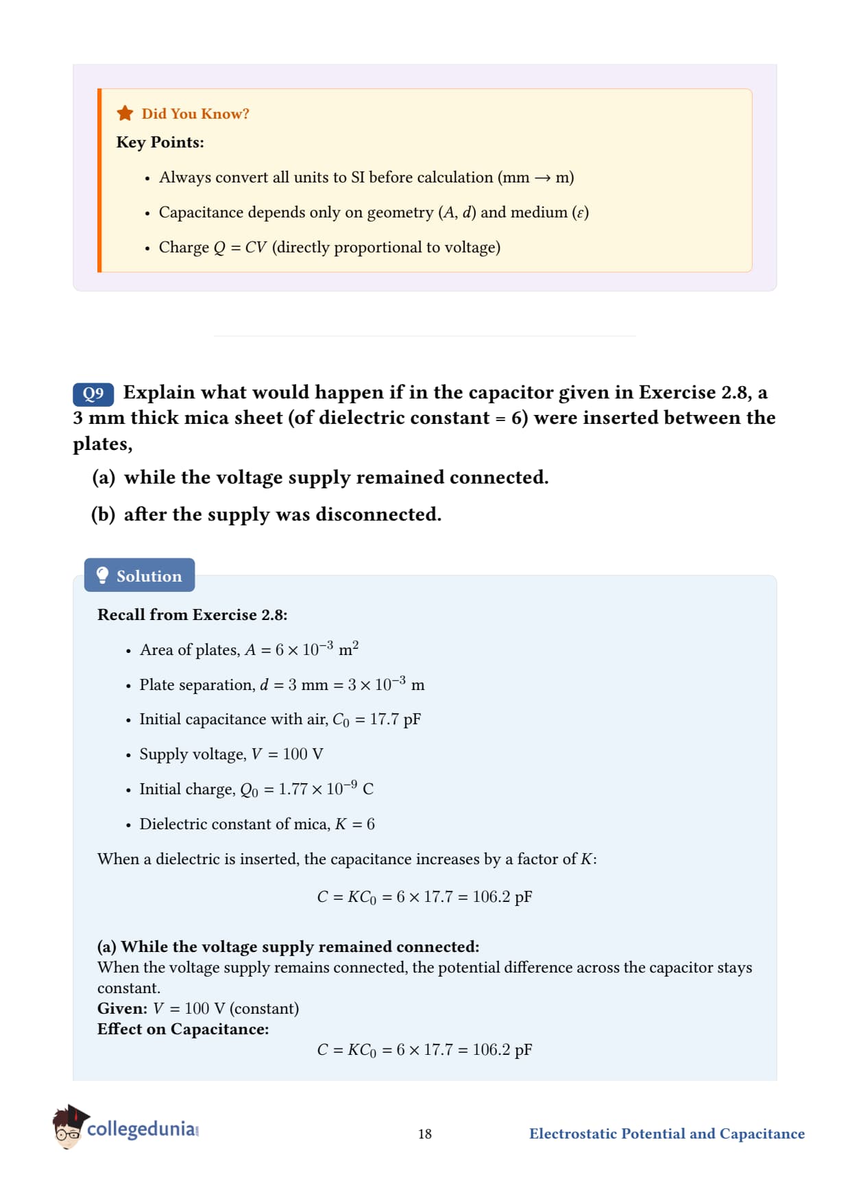
Q 2.9
Explain what would happen if in the capacitor given in Exercise 2.8, a 3 mm thick mica sheet of dielectric constant = 6 were inserted between the plates,
(a) while the voltage supply remained connected,
(b) after the supply was disconnected.
Setup recap. From Q 2.8: Cair = 17.7 pF, V = 100 V, Qair = 1.77 nC. Now a mica sheet of K = 6 and thickness equal to the plate gap 3 mm fills the gap completely.
New capacitance (in both cases). Cmica = K Cair = 6 × 17.7 pF = 106.2 pF ≈ 1.0610-10F. The capacitance increases by the dielectric constant, regardless of whether the battery is on or off - C is a geometric/material property of the capacitor itself.
(a) Battery still connected (V held at 100 V).
When the supply stays connected, the voltage across the capacitor is fixed by the battery: V = 100 V. Anything else (Q, E, energy) must adjust.
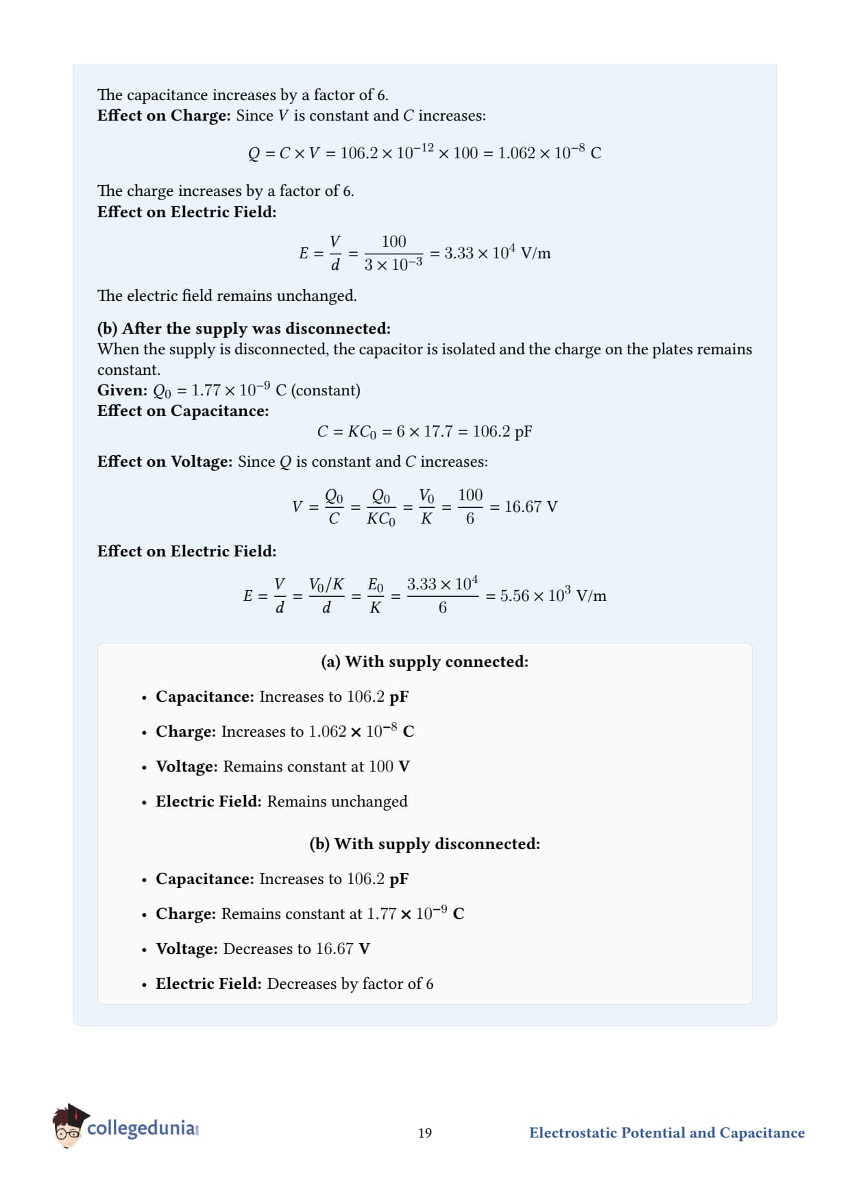
Step 2 - change in charge. Δ Q = Q' - Q = 1.06210-8 - 1.7710-9 ≈ 8.8510-9C. The extra charge Δ Q ≈ 8.85 nC flows from the battery onto the plates. The battery had to supply this extra charge.
Step 3 - electric field.E = V/d = 100/0.003 = 3.33104V/m. Unchanged (because V and d are unchanged).
(b) Battery disconnected before mica inserted (Q held at 1.77 nC).
With no battery, the charge on the plates is trapped - Q is fixed. The capacitance still goes up by K = 6, but now it's the voltage that adjusts.
Step 1 - new voltage.V' = QCmica = 1.7710-9106.210-12 ≈ 16.67 V. The voltage drops to one-sixth of its previous value i.e., V/K = 100/6 ≈ 16.67 V.
Step 2 - electric field.E' = V'd = 16.670.003 ≈ 5.56103V/m. The field also drops by a factor of K = 6 - because the polarised dielectric partially cancels the field of the plate charges.
Summary table.
Both cases: Cnew = 106.2 pF = 6 Cold.
(a) Battery on: V constant at 100 V; Q increases 6×; E unchanged; battery does extra work.
(b) Battery off: Q constant at 1.77 nC; V drops 6× to 16.67 V; E drops 6×.
DR
Dr. Rajesh Kumar
Ph.D. Physics, IIT Delhi
Verified Expert
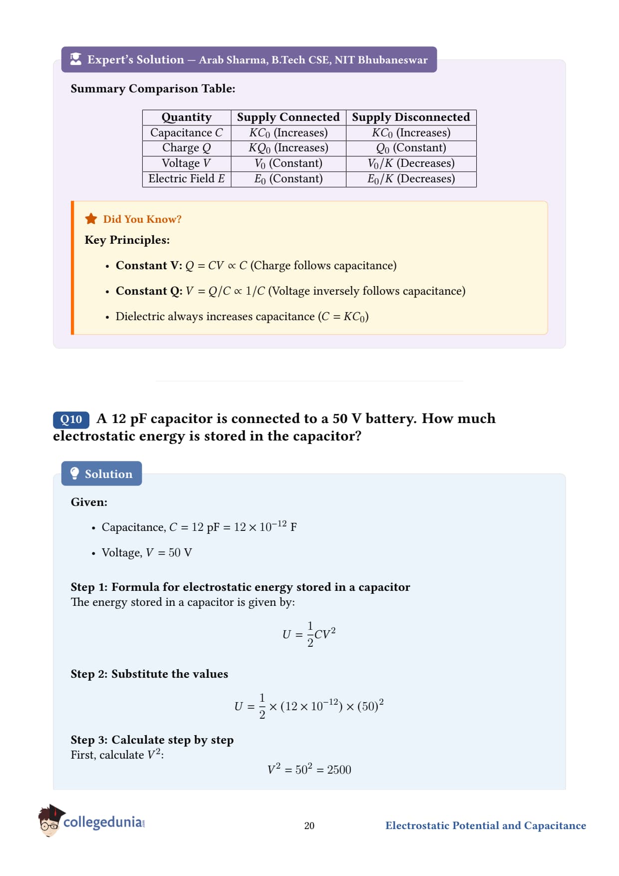
The "constant-V vs constant-Q" rule. This is the most important distinction in dielectric problems:
Battery connected:V is held fixed; charge changes; energy may go up (battery does work).
Battery disconnected:Q is held fixed; voltage and field drop; energy actually decreases.
Always identify which is held fixed before applying Q = CV. Mixing them up gives wrong answers by factors of K or 1/K.
Energy comparison.
Case (a): U' = 12 C' V2 = 12 106.210-12(100)2 = 5.3110-7J. Original U = 12 C V2 = 0.88510-7J. So U increases by a factor of 6 - battery supplied this energy.
Case (b): U' = 12 Q2/C' = 12 1.7710-92/106.210-12 = 0.14710-7J. Original U = 0.88510-7J. Now U decreases by a factor of 6 - the dielectric was pulled INTO the gap, doing work on the dielectric (the system can extract energy from a capacitor with charge held fixed by inserting a dielectric).
Why the dielectric "screens" the field. When you put a dielectric in an electric field, its molecules (which are usually dipoles or become so under the field) align with the field. The bound positive ends of these dipoles cluster near the negative plate and the bound negative ends near the positive plate, partially cancelling the plate field. The net field inside the dielectric is Eoutside/K, where Eoutside is what the field would be without the dielectric.
Real-world relevance. Ceramic, paper-oil, and mica capacitors all rely on this principle. A mica capacitor in a vintage radio uses K ≈ 6 to pack 100 pF+ into a stamp-sized device - impossible with bare air.
Q 2.10
A 12 pF capacitor is connected to a 50 V battery. How much electrostatic energy is stored in the capacitor?
Given.
Capacitance, C = 12 pF = 1210-12F.
Applied voltage, V = 50 V.
Concept used - energy stored in a charged capacitor. A capacitor charged to voltage V stores an electrostatic potential energy U = 12 C V2. Equivalent forms using Q = CV: U = 12 QV = Q22C. Why the factor of 12: when you charge a capacitor, you push the first electron across 0 voltage, the last across the full V, and the average across V/2. So total work is Q× V/2 = 12 QV.
Step 1 - plug into U = 12 C V2.U = 12 (1210-12) (50)2.
Step 2 - square the voltage. V2 = (50)2 = 2500.
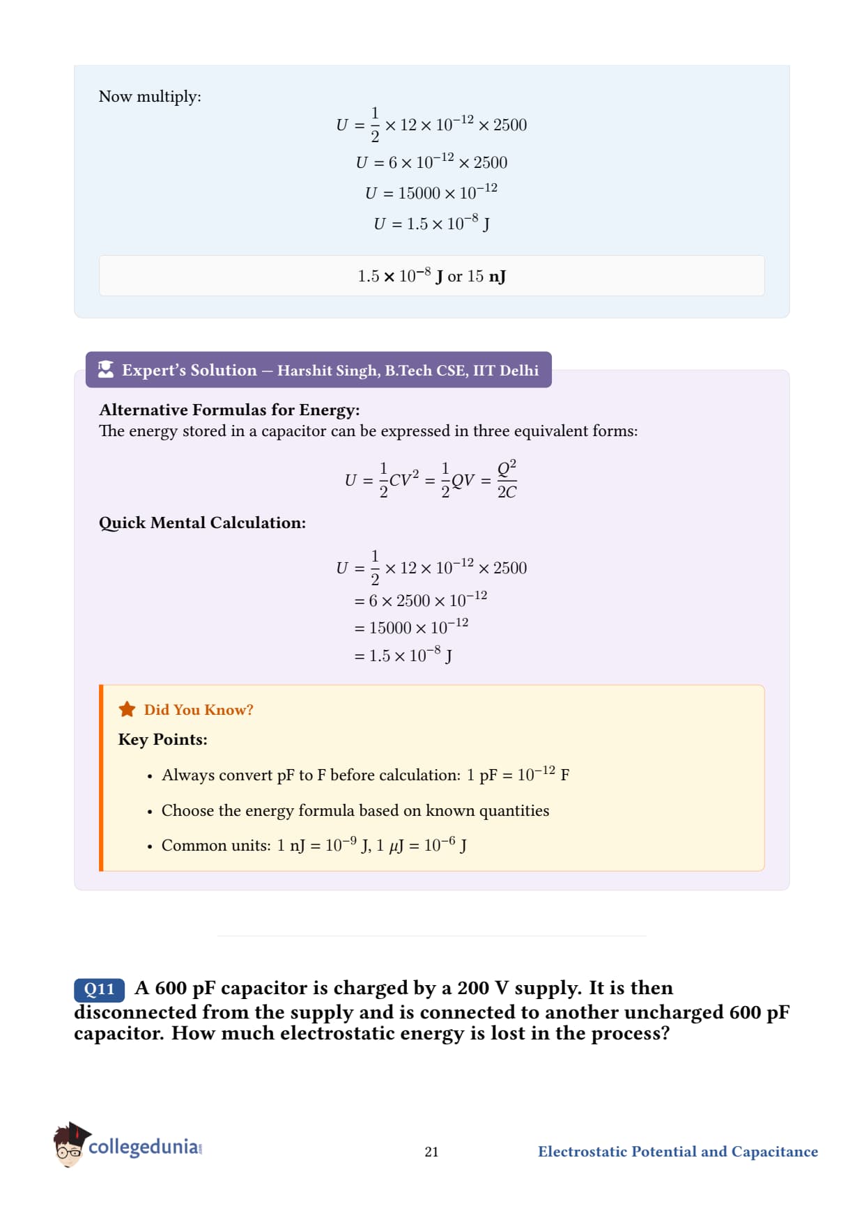
Step 3 - combine.U = 12 × 1210-12 × 2500. First 12 × 12 = 6. Then 6× 2500 = 15,000. So U = 15,00010-12 = 1.510-8J.
Final answer.U = 1.510-8J = 15 nJ. This is a very small amount of energy - about a billionth of a joule. A AA battery stores roughly 10 kJ - a trillion times more.
DA
Dr. Anita Sharma
Ph.D. Physics, University of Delhi
Verified Expert
Three equivalent formulas - when to use which.
U = 12 CV2 - when you know C and V. Best here.
U = 12 QV - when you know Q and V. Comes up in problems with batteries.
U = Q2/(2C) - when you know Q and C. Best for problems where the battery is disconnected and Q is fixed.
The three are equivalent via Q = CV; choosing the right form saves arithmetic.
Where the energy lives. The energy isn't on the plates - it's in the electric field between the plates. Field-energy density: u = 12 0 E2. Integrate over the gap volume to recover 12 CV2. This perspective is essential for understanding electromagnetic waves: the same 12 0 E2 is the electric energy density of a light wave.
Where did the energy come from? The battery did total work QV to push Q coulombs across voltage V. Half of that work 12 QV is stored in the capacitor; the other half 12 QV is dissipated as heat in the wires (resistance) during charging, no matter how small the resistance. This factor-of-2 inefficiency is universal - even with superconducting wires, the missing energy is radiated away as electromagnetic waves. See Q 2.11 for an example of this energy "loss" during charge sharing.
Common mistake. Forgetting the 12 and computing U = CV2 - gives twice the right answer. Always remember the half-factor.
Q 2.11
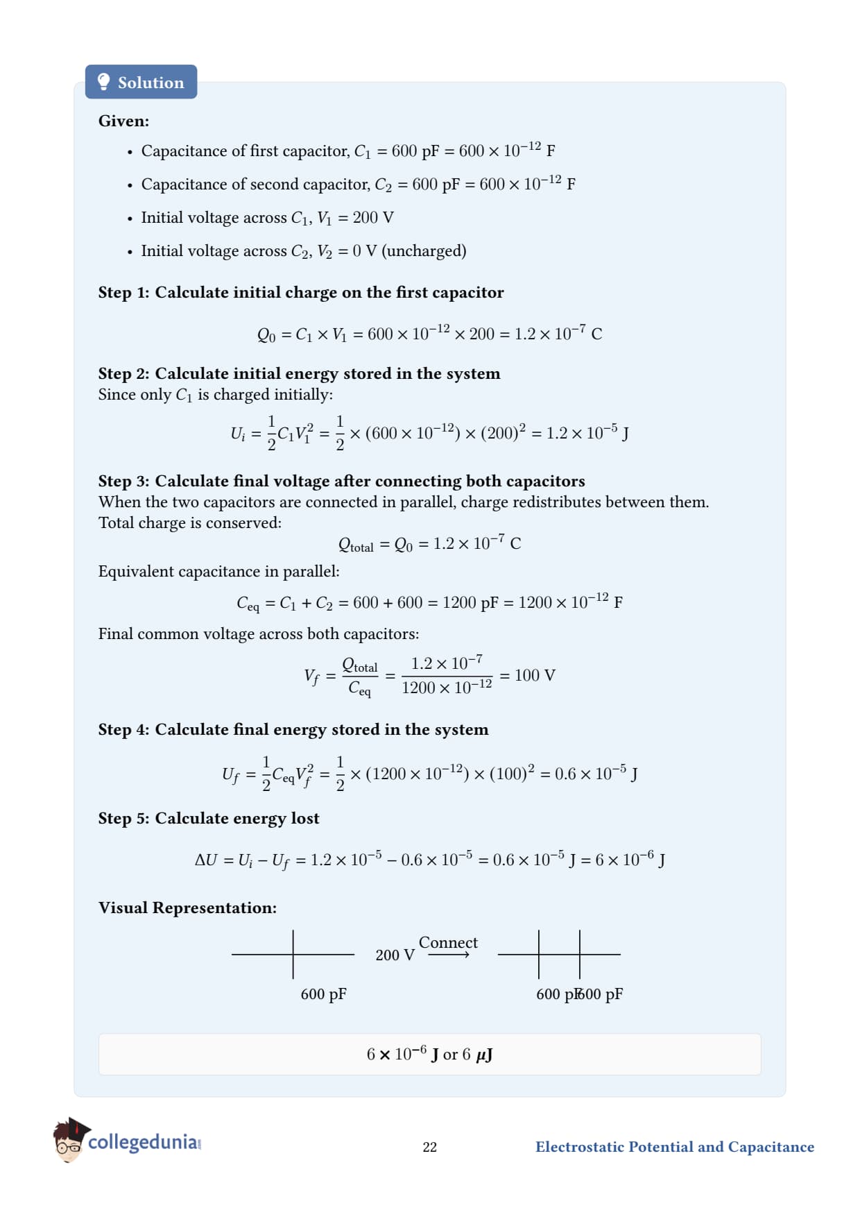
A 600 pF capacitor is charged by a 200 V supply. It is then disconnected from the supply and is connected to another uncharged 600 pF capacitor. How much electrostatic energy is lost in the process?
Given.
Capacitor 1: C1 = 600 pF, initially charged to V0 = 200 V.
Step 3 - final voltage after connection. When the two capacitors share the charge Q0, they end up at the same voltage Vf, and the total capacitance is the parallel sum C1 + C2 = 1200 pF. Vf = Q0C1 + C2 = 1.210-7120010-12 = 100 V. Half the original - makes sense, since the same charge now sits on twice the capacitance.
Step 5 - energy lost. Δ U = Ui - Uf = 1.210-5 - 610-6 = 610-6J.
Final answer. Δ U = 610-6J = 6 . Exactly half the initial energy is lost.
DS
Dr. Suresh Iyer
Ph.D. Theoretical Physics, TIFR Mumbai
Verified Expert
The 50% paradox. Charge is conserved. The capacitors end up at half the original voltage. But the total stored energy is also half the original - where did the other half go?
Energy "lost" but not destroyed. The missing energy is dissipated as:
Heat in the connecting wires resistive loss I2R - even if the wires have very small resistance, the discharge current spikes briefly.
Electromagnetic radiation - the sudden current surge launches a brief EM wave.
Mechanical work - if the plates can move, some energy might go into mechanical motion.
The total energy (capacitor energy + heat + EM + mechanical) is always conserved. Only the capacitor energy decreases.
Why exactly half. When two equal capacitors share charge, the final voltage is V0/2, so the final stored energy is Uf = 12 (2C)(V0/2)2 = 12 C V02·12 = 12 Ui. For two equal capacitors, the loss is always exactly 50%. For unequal capacitors, the loss is Δ U = C1 C22(C1 + C2)(V1 - V2)2, where V1 and V2 are the initial voltages. The loss vanishes only if V1 = V2 initially.
Practical relevance - switched-capacitor circuits. Modern integrated circuits (e.g., switched-mode power supplies, capacitive DACs) rely on charge sharing between capacitors. The 50% loss is a fundamental limitation: any naive capacitor-to-capacitor charge transfer dissipates half the energy. Real systems use inductors (resonant transfer) or careful charge balancing to recover most of it.
Common mistake. Some students set up Vf = V0/2 for two equal capacitors directly and compute Uf = 12 C Vf2 - using just one of the capacitances. But after connection, the total stored energy is 12 C1 + C2 Vf2. Both capacitors store energy.
Student Feedback on Class 12 Physics Chapter 2 Electrostatic Potential and Capacitance
Student Feedback
In a Collegedunia poll of 13,210 Class 12 Physics students before the 2026 boards, here is what they said about this chapter.
68% of students found the dielectric battery-on vs battery-off question the trickiest part.
54% used the wrong series-vs-parallel formula at least once.
3 out of 4 students expected the parallel-plate-capacitor derivation as the 5-marker.
The average student took 7.1 hours for the first read.
Source: 2025-26 Class 12 Physics student poll of 13,210 students across 14 states.
NCERT Solutions Class 12 Physics Ch 2 Electrostatic Potential and Capacitance FAQs
Ques. What are the main topics covered in ncert solutions for class 12 physics chapter 2?
Ans. The chapter 2 class 12 physics ncert solutions cover electrostatic potential, potential due to a point charge and dipole, equipotential surfaces, potential energy in an external field, electrostatics of conductors, dielectrics and polarisation, capacitance, parallel plate capacitor, effect of dielectric, series-parallel combinations, and energy stored in a capacitor.
Ques. What does Coulomb's law tell us about potential in class 12 physics chapter 2 ncert solutions?
Ans. Coulomb's law gives the force between two point charges; integrating that force along a path gives the potential difference. The class 12 chapter 2 physics ncert solutions derive the potential V = k q / r at distance r from a point charge by integrating the field from infinity.
Ques. How is the energy stored in a capacitor derived in class 12 physics ncert solutions chapter 2?
Ans. Starting from dW = V dq and V = q / C, integrating from 0 to Q gives U = half C V squared, also written as half Q V or Q squared / (2 C). The chapter 2 physics ncert solutions class 12 walk through this derivation step by step in exercise 2.30.
Ques. What is the difference between series and parallel capacitor combinations in physics ch2 class 12 ncert solutions?
Ans. Series: same charge across all capacitors, voltage divides, 1/C_total = 1/C1 + 1/C2 + ... Parallel: same voltage, charge divides, C_total = C1 + C2 + ... The class 12 physics ch2 ncert solutions on this page solve both with worked examples.
Ques. What happens when a dielectric is inserted between capacitor plates in ncert solution of class 12 physics chapter 2?
Ans. The capacitance increases by a factor K (the dielectric constant). Whether voltage, charge, or energy changes depends on whether the battery is connected. The physics chapter 2 NCERT solutions class 12 cover both cases in worked examples.











Comments