


CEED 2020 Question paper with answer key pdf conducted on January 18, 2020 is available for download. The exam was successfully organized by Indian Institute of Technology Bombay. In terms of difficulty level, CEED 2020 was of Moderate level. The question paper comprised a total of 46 questions divided among 2 sections.
CEED 2020 Question Paper with Solutions PDF
| CEED 2020 Question Paper with Solutions PDF | Check Solutions |

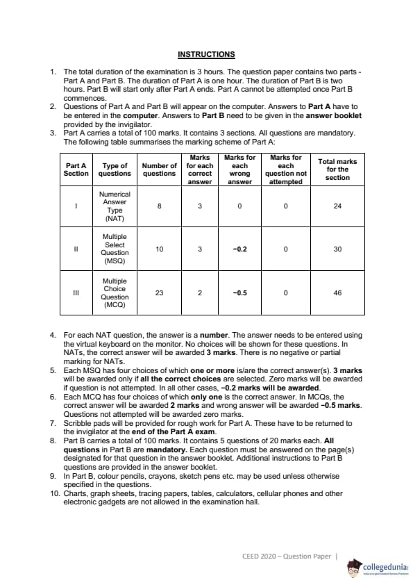
Two views of a solid object are shown. Count the number of surfaces.

While Lilo was playing with a toy tractor, she rolled it over an ink drop. The image on the right shows the ink drop and the marks on the floor left by tractor's wheels. The diameter of the back wheel of the tractor is 1.5 times that of its front wheel. What is the number of revolutions made by the front wheel between the ink drop and the last mark?

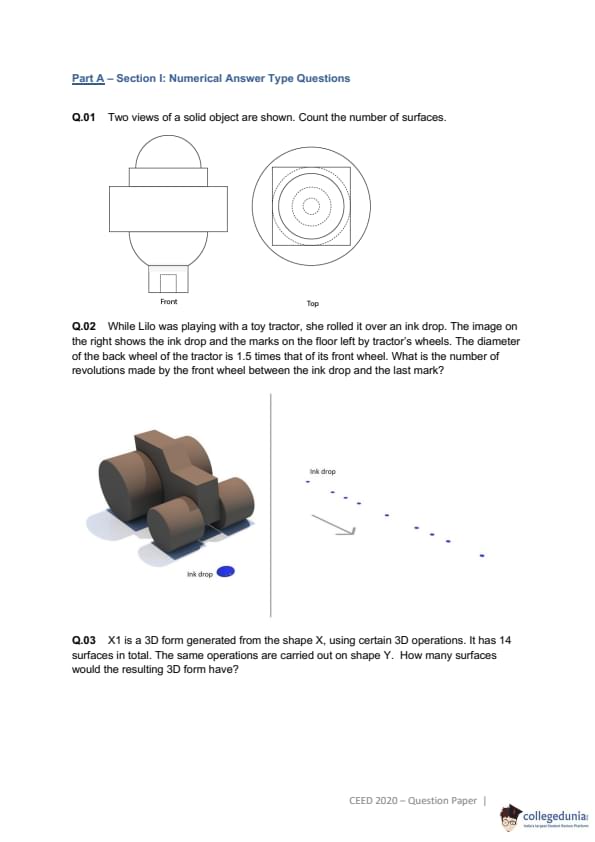
X1 is a 3D form generated from the shape X, using certain 3D operations. It has 14 surfaces in total. The same operations are carried out on shape Y. How many surfaces would the resulting 3D form have?

Count the total number of triangles.

What is the shortest distance (in cm) for the red dot to reach the position x? The dot can travel only along the grid lines shown.

What is the number of differences between the two images?

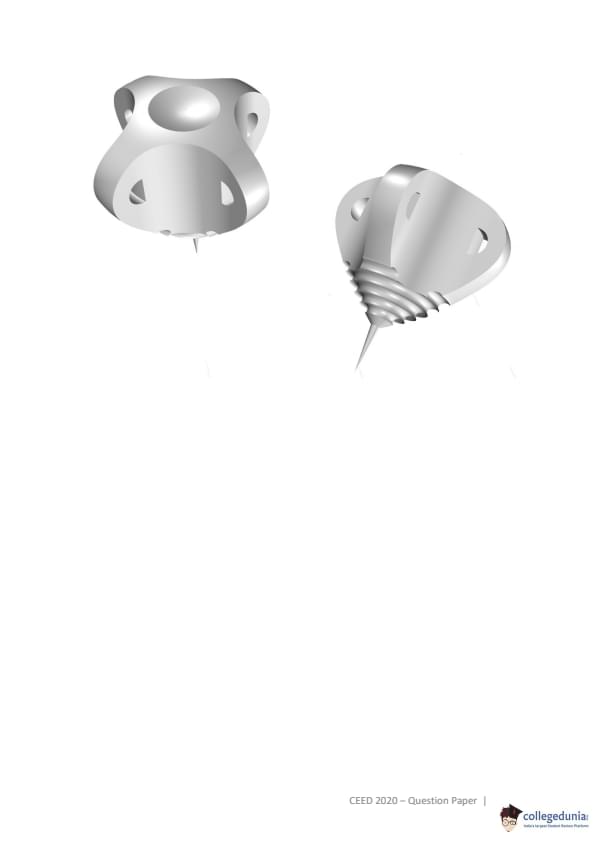
The figure shows two views of an object. What is the least volume of a rectangular box required to pack six such objects?

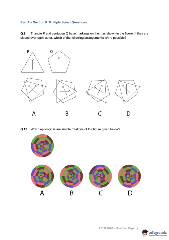
The figure shows two views of the same solid. Count the number of surfaces.

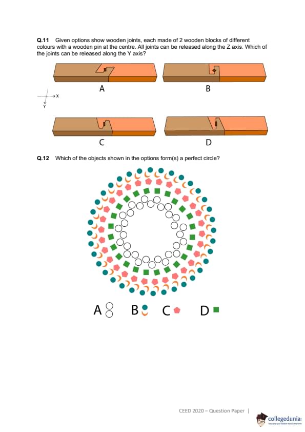
Triangle P and pentagon Q have markings on them as shown in the figure. If they are placed over each other, which of the following arrangements is/are possible? \

Which option(s) is/are simple rotations of the figure given below?

Given options show wooden joints, each made of 2 wooden blocks of different colours with a wooden pin at the centre. All joints can be released along the Z axis. Which of the joints can be released along the Y axis?

Which of the objects shown in the options form(s) a perfect circle?

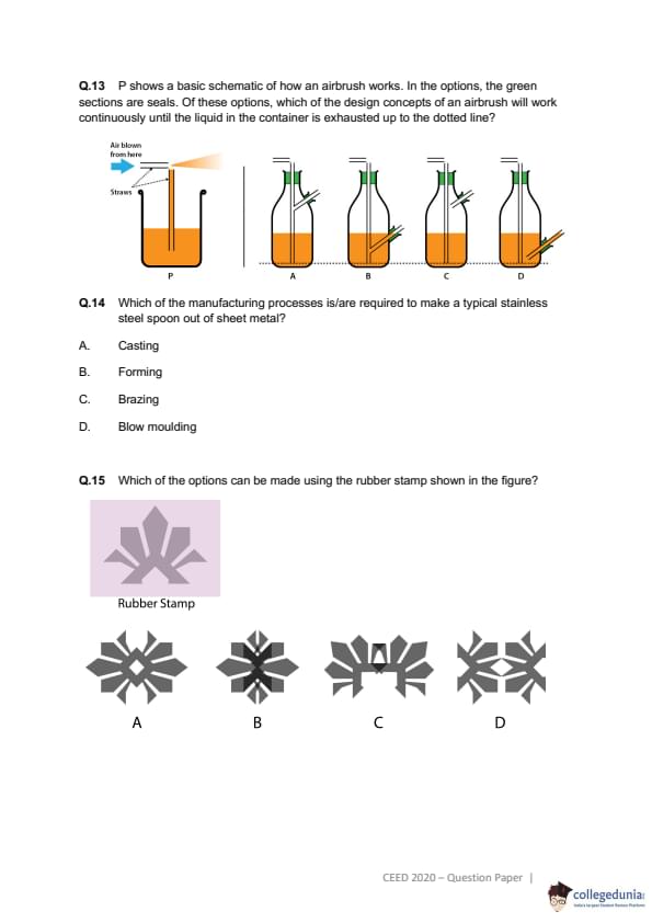
P shows a basic schematic of how an airbrush works. In the options, the green sections are seals. Of these options, which of the design concepts of an airbrush will work continuously until the liquid in the container is exhausted up to the dotted line?

Which of the manufacturing processes is/are required to make a typical stainless steel spoon out of sheet metal?
Which of the options can be made using the rubber stamp shown in the figure?

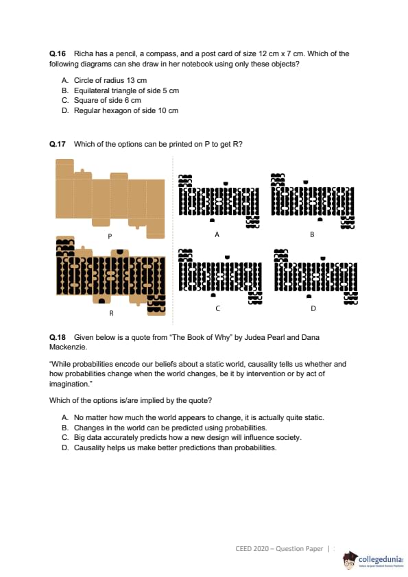
Richa has a pencil, a compass, and a post card of size 12 cm x 7 cm. Which of the following diagrams can she draw in her notebook using only these objects?
Which of the options can be printed on P to get R?

Given below is a quote from "The Book of Why" by Judea Pearl and Dana Mackenzie.
"While probabilities encode our beliefs about a static world, causality tells us whether and how probabilities change when the world changes, be it by intervention or by act of imagination."
Which of the options is/are implied by the quote?
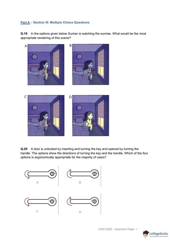
In the options given below Suman is watching the sunrise. What would be the most appropriate rendering of this scene?

A door is unlocked by inserting and turning the key and opened by turning the handle. The options show the directions of turning the key and the handle. Which of the four options is ergonomically appropriate for the majority of users?

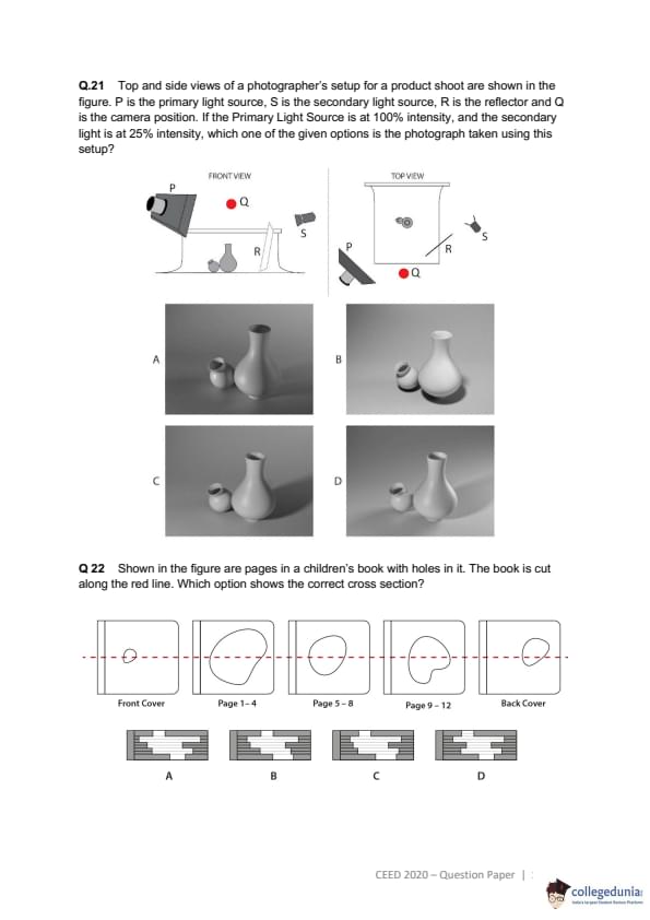
Top and side views of a photographer's setup for a product shoot are shown in the figure. P is the primary light source, S is the secondary light source, R is the reflector and Q is the camera position. If the Primary Light Source is at 100% intensity, and the secondary light is at 25% intensity, which one of the given options is the photograph taken using this setup?

Shown in the figure are pages in a children's book with holes in it. The book is cut along the red line. Which option shows the correct cross section?

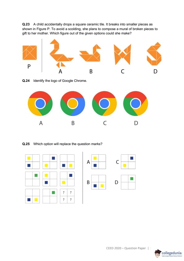
A child accidentally drops a square ceramic tile. It breaks into smaller pieces as shown in Figure P. To avoid a scolding, she plans to compose a mural of broken pieces to gift to her mother. Which figure out of the given options could she make?

Identify the logo of Google Chrome.

Which option will replace the question marks?

A strip of stickers is shown in the figure. What is the result after all the stickers have been removed from it?

A dice is rolled from its current position (A) through B, C and D to stop at position E. What will be the number on the top of the dice at position E, if each pair of its opposite faces adds to seven?

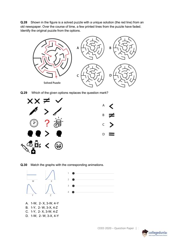
Shown in the figure is a solved puzzle with a unique solution (the red line) from an old newspaper. Over the course of time, a few printed lines from the puzzle have faded. Identify the original puzzle from the options.

Which of the given options replaces the question mark?

Match the graphs with the corresponding animations.

Which option matches the order of the paintings shown?

From the options, select the illustration that matches the given silhouette.

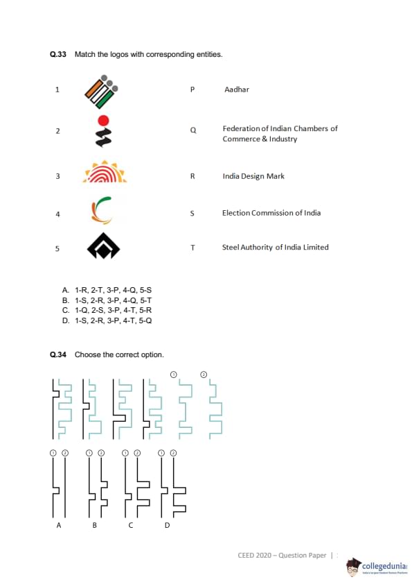
Match the logos with corresponding entities.

Choose the correct option.

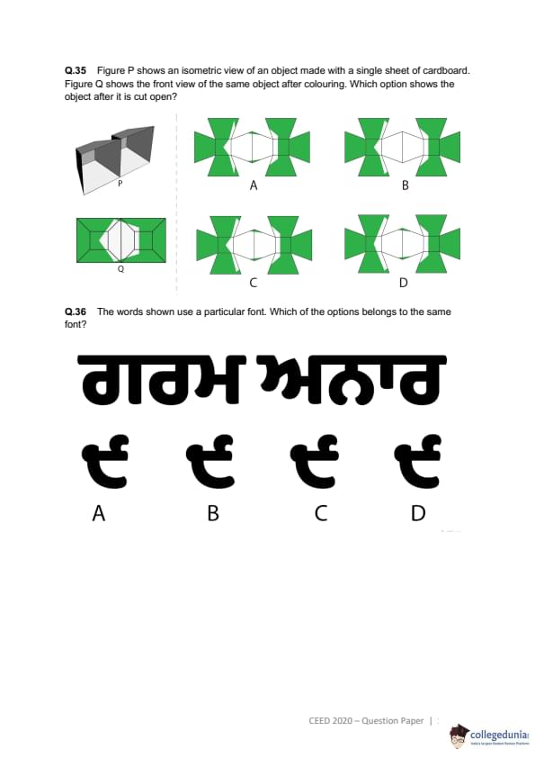
Figure P shows an isometric view of an object made with a single sheet of cardboard. Figure Q shows the front view of the same object after colouring. Which option shows the object after it is cut open?

The words shown use a particular font. Which of the options belongs to the same font?

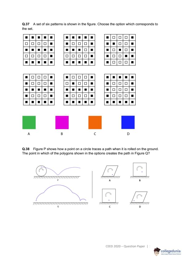
A set of six patterns is shown in the figure. Choose the option which corresponds to the set.

Figure P shows how a point on a circle traces a path when it is rolled on the ground. The point in which of the polygons shown in the options creates the path in Figure Q?

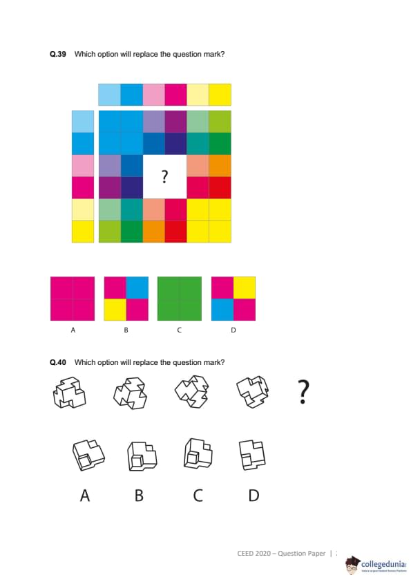
Which option will replace the question mark?

Which option will replace the question mark?

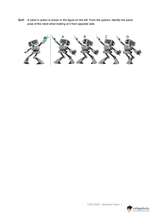
A robot in action is shown in the figure on the left. From the options, identify the same pose of the robot when looking at it from opposite side.

Sketching (20 marks = 10+10)
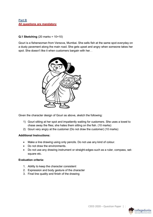
Gouri is a fisherwoman from Versova, Mumbai. She sells fish at the same spot everyday on a dusty pavement along the main road. She gets upset and angry when someone takes her spot. She doesn't like it when customers bargain with her..

Given the character design of Gouri as above, sketch the following:
1) Gouri sitting at her spot and impatiently waiting for customers. She uses a towel to chase away the flies; she hates them sitting on the fish. (10 marks)
2) Gouri very angry at the customer (Do not draw the customer) (10 marks)
Additional Instructions:
Make a line drawing using only pencils. Do not use any kind of colour.
Do not draw the environments.
Do not use any drawing instrument or straight-edges such as a ruler, compass, set-square etc.
\textbf{Evaluation criteria:}
Ability to keep the character consistent
Expression and body gesture of the character
Final line quality and finish of the drawing
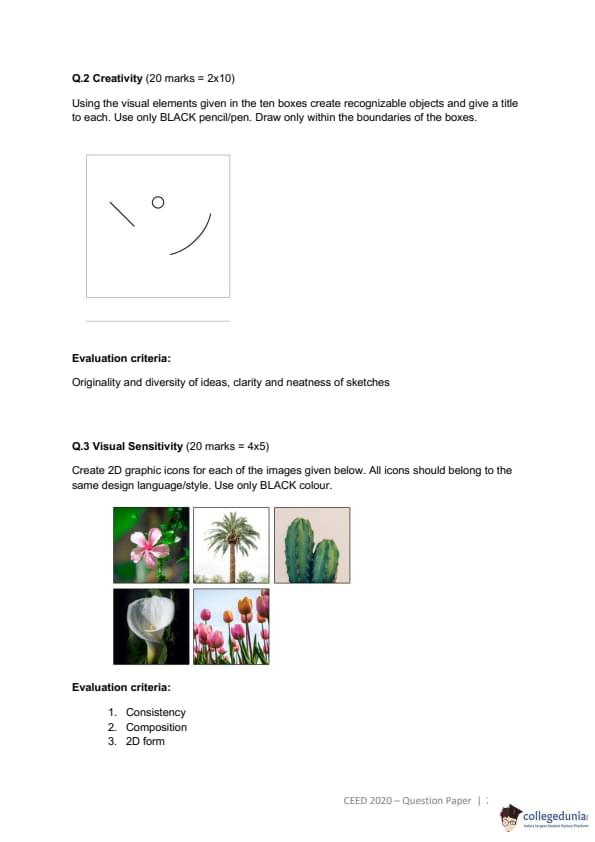
Creativity (20 marks = 2x10)
Using the visual elements given in the ten boxes create recognizable objects and give a title to each. Use only BLACK pencil/pen. Draw only within the boundaries of the boxes.

Evaluation criteria:
Originality and diversity of ideas, clarity and neatness of sketches
Visual Sensitivity (20 marks = 4x5)
Create 2D graphic icons for each of the images given below. All icons should belong to the same design language/style. Use only BLACK colour.

Evaluation criteria:
Consistency
Composition
2D form
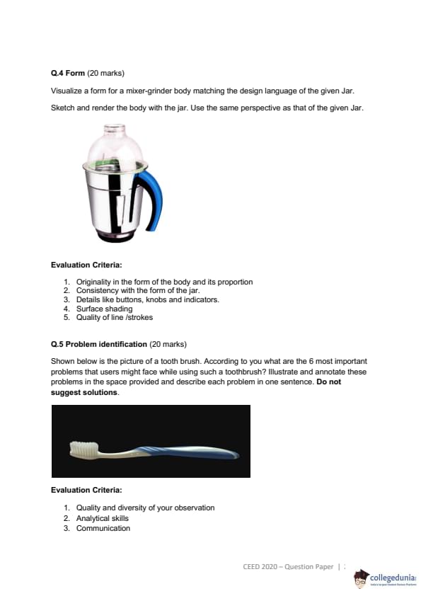
Form (20 marks)
Visualize a form for a mixer-grinder body matching the design language of the given Jar. Sketch and render the body with the jar. Use the same perspective as that of the given Jar.

Evaluation Criteria:
Originality in the form of the body and its proportion
Consistency with the form of the jar.
Details like buttons, knobs and indicators.
Surface shading
Quality of line /strokes
Problem identification (20 marks)
Shown below is the picture of a tooth brush. According to you what are the 6 most important problems that users might face while using such a toothbrush? Illustrate and annotate these problems in the space provided and describe each problem in one sentence. Do not suggest solutions.

Evaluation Criteria:
Quality and diversity of your observation
Analytical skills
Communication


Comments