


Kerala Plus Two 2025 Physics (SY-624) Model Question Paper with Solutions PDFs are now available for download. The Kerala Plus Two Physics Model Examination 2025 was conducted by the Directorate of Higher Secondary Education (DHSE), Kerala, to help students prepare for the final board exams. The paper is designed as per the latest syllabus and exam pattern prescribed for the academic year 2025–26.
Kerala Plus Two 2025 Physics (SY-624) Model Question Paper with solutions
| Kerala Plus Two 2025 Physics (SY-624) Model Question Paper | Check Solutions |

The SI unit of electric charge is ________.
View Solution
Step 1: Understanding Electric Charge.
Electric charge is a fundamental physical quantity that represents the amount of electricity carried by a body. It is responsible for electric forces and electrical phenomena.
Step 2: SI Unit of Electric Charge.
In the International System of Units (SI), the standard unit used to measure electric charge is the coulomb. It is denoted by the symbol \( C \).
Step 3: Definition of Coulomb.
One coulomb is defined as the amount of electric charge transported by a current of one ampere flowing for one second.
Step 4: Conclusion.
Hence, the SI unit of electric charge is coulomb (C).
Quick Tip: Remember: Electric current is measured in ampere, time in second, and electric charge in coulomb.
A hollow metal sphere of radius 1 cm is charged with a potential 10 V on its surface. Then the potential at the centre of the sphere is
View Solution
Step 1: Understanding the nature of a hollow metal sphere
A hollow metal sphere is a conductor. In electrostatic equilibrium, the electric field inside a conductor is zero. Hence, there is no change in electric potential inside the conductor.
Step 2: Concept of electric potential inside a conductor
Since the electric field inside a conducting sphere is zero, the electric potential remains constant throughout the interior of the sphere. This constant potential is equal to the potential at the surface of the sphere.
Step 3: Applying the given data
The potential at the surface of the hollow metal sphere is given as 10 V. Therefore, the potential at every point inside the sphere, including the centre, is also 10 V.
Step 4: Conclusion
Thus, the potential at the centre of the hollow metal sphere is equal to the surface potential.
Final Answer:
10 V Quick Tip: For a charged conductor in electrostatic equilibrium, the electric field inside is zero and the potential remains constant throughout the interior.
Give the equation of motional emf induced in a conductor of length \( l \), moving with velocity \( v \) in a uniform magnetic field \( B \).
View Solution
Step 1: Understanding Motional EMF.
Motional electromotive force (emf) is produced when a conductor moves through a magnetic field. Due to this motion, free charges present in the conductor experience a magnetic force, which causes separation of charges and hence an emf is induced across the ends of the conductor.
Step 2: Magnetic Force on Charges.
When a conductor of length \( l \) moves with velocity \( v \) perpendicular to a uniform magnetic field \( B \), each charge \( q \) inside the conductor experiences a magnetic force given by:
\[ F = q v B \]
This force pushes positive and negative charges in opposite directions, creating an electric field inside the conductor.
Step 3: Development of Electric Field.
Due to charge separation, an electric field \( E \) is established inside the conductor. At equilibrium, the electric force balances the magnetic force:
\[ qE = qvB \] \[ E = vB \]
Step 4: Expression for Motional EMF.
The induced emf \( \varepsilon \) across the length of the conductor is given by:
\[ \varepsilon = E \times l \]
Substituting the value of \( E \):
\[ \varepsilon = B l v \]
Step 5: Final Equation.
Thus, the equation of motional emf induced in the conductor is:
\[ \boxed{\varepsilon = B l v} \]
Quick Tip: Motional emf is maximum when the conductor moves perpendicular to the magnetic field.
What do you mean by displacement current?
View Solution
Step 1: Background of Displacement Current.
The concept of displacement current was introduced by James Clerk Maxwell to modify Ampere’s circuital law. He realized that in situations where the electric field changes with time, magnetic fields can still be produced even in the absence of conduction current.
Step 2: Understanding the Concept.
Displacement current is not a current due to the actual flow of electric charges. Instead, it arises due to a time-varying electric field. It plays a crucial role in maintaining the continuity of current in circuits, especially in devices like capacitors.
Step 3: Displacement Current in a Capacitor.
When a capacitor is connected to an alternating voltage source, current flows in the external circuit. However, between the plates of the capacitor, there is no conduction current. Still, a changing electric field exists, which gives rise to displacement current.
Step 4: Mathematical Expression.
The displacement current \( I_d \) is given by:
\[ I_d = \varepsilon_0 \frac{d\Phi_E}{dt} \]
where \( \varepsilon_0 \) is the permittivity of free space and \( \frac{d\Phi_E}{dt} \) is the rate of change of electric flux.
Step 5: Importance of Displacement Current.
Displacement current completes Ampere–Maxwell law and explains the propagation of electromagnetic waves. Without this concept, Maxwell’s equations would be incomplete.
Quick Tip: Displacement current arises due to changing electric field, not due to movement of charges.
Two lenses of powers \(+7\,D\) and \(-3\,D\) are combined. The focal length of the combination would be
View Solution
Step 1: Recall the formula for power of a combination of lenses
When thin lenses are placed in contact, the total power of the combination is the algebraic sum of the individual powers: \[ P_{total} = P_1 + P_2 \]
Step 2: Substitute the given values
Given: \[ P_1 = +7\,D, \quad P_2 = -3\,D \] \[ P_{total} = 7 - 3 = +4\,D \]
Step 3: Find the focal length of the combination
The relation between power \(P\) and focal length \(f\) (in metres) is: \[ P = \frac{1}{f} \] \[ f = \frac{1}{4} \,m = 0.25\,m \]
Step 4: Convert metres into centimetres
\[ 0.25\,m = 25\,cm \]
Since the power is positive, the focal length is also positive.
Step 5: Conclusion
The focal length of the combined lens system is \(+25\) cm.
Final Answer: \( +25 \) cm Quick Tip: For lenses in contact, always add their powers algebraically first; then convert the resulting power into focal length using \( f = \frac{1}{P} \).
Ionisation energy of hydrogen atom is ________ eV.
View Solution
Step 1: Meaning of Ionisation Energy.
Ionisation energy is the minimum amount of energy required to remove the most loosely bound electron from an isolated gaseous atom in its ground state.
Step 2: Ionisation Energy of Hydrogen Atom.
In a hydrogen atom, the electron is present in the ground state (\(n = 1\)). The energy of this state is \(-13.6 \, eV\).
Step 3: Energy Required to Remove the Electron.
To completely remove the electron from the hydrogen atom (i.e., to take it to infinity), an energy equal to \(13.6 \, eV\) is required.
Step 4: Final Answer.
Hence, the ionisation energy of hydrogen atom is \(13.6 \, eV\).
Quick Tip: The ionisation energy of hydrogen atom is a standard value and is always equal to 13.6 eV.
Ratio of the radii of two nuclei of mass numbers \(A_1\) and \(A_2\) is ________.
View Solution
Step 1: Formula for Nuclear Radius.
The radius of a nucleus is given by the relation:
\[ R = R_0 A^{1/3} \]
where \(R\) is the radius of the nucleus, \(A\) is the mass number, and \(R_0\) is a constant.
Step 2: Radii of the Two Nuclei.
For the first nucleus:
\[ R_1 = R_0 A_1^{1/3} \]
For the second nucleus:
\[ R_2 = R_0 A_2^{1/3} \]
Step 3: Ratio of the Radii.
Taking the ratio of \(R_1\) and \(R_2\):
\[ \frac{R_1}{R_2} = \frac{R_0 A_1^{1/3}}{R_0 A_2^{1/3}} = \left( \frac{A_1}{A_2} \right)^{1/3} \]
Step 4: Final Answer.
Thus, the ratio of the radii of the two nuclei is \[ \left( \frac{A_1}{A_2} \right)^{1/3}. \]
Quick Tip: Nuclear radius is proportional to the cube root of the mass number.
Name a material which is used to make wire bound standard resistor. Give reason.
View Solution
Step 1: Identification of the Material.
The material commonly used to make a wire bound standard resistor is Manganin.
Step 2: Properties of Manganin.
Manganin is an alloy of copper, manganese, and nickel. It has several properties that make it suitable for use in standard resistors.
Step 3: Reason for Using Manganin.
The most important reason for using manganin is that it has a very low temperature coefficient of resistance. This means that its resistance remains almost constant even when the temperature changes.
Step 4: Additional Advantages.
Manganin also has high electrical resistivity and good mechanical stability. Due to these properties, it ensures accurate and stable resistance values over long periods of time.
Step 5: Conclusion.
Therefore, manganin is used in wire bound standard resistors because it provides stable resistance that is nearly independent of temperature variations.
Quick Tip: Materials with low temperature coefficient of resistance are preferred for making standard resistors.
State Gauss’s law in magnetism.
View Solution
Step 1: Statement of Gauss’s Law in Magnetism.
Gauss’s law in magnetism states that the total magnetic flux through any closed surface is always zero.
Step 2: Mathematical Expression.
Mathematically, Gauss’s law in magnetism is expressed as:
\[ \oint \vec{B} \cdot d\vec{A} = 0 \]
where \( \vec{B} \) is the magnetic field and \( d\vec{A} \) is the area element of the closed surface.
Step 3: Physical Interpretation.
This law implies that magnetic monopoles do not exist in nature. Magnetic field lines always form closed continuous loops and do not begin or end at any point.
Step 4: Significance of the Law.
Gauss’s law in magnetism helps in understanding the fundamental nature of magnetic fields and supports the fact that every magnet has both north and south poles.
Step 5: Conclusion.
Hence, Gauss’s law in magnetism confirms that the net magnetic flux through a closed surface is zero under all circumstances.
Quick Tip: Unlike electric charges, isolated magnetic poles have never been observed.
A power transmission line feeds power at 2200 V with a current of 5 A to a step-down transformer with its primary winding having 4000 turns. Calculate the number of turns and current in the secondary in order to get output power at 220 V.
View Solution
Given data:
Primary voltage, \( V_p = 2200 \, V \)
Primary current, \( I_p = 5 \, A \)
Number of turns in primary, \( N_p = 4000 \)
Secondary voltage, \( V_s = 220 \, V \)
Step 1: Calculation of number of turns in the secondary
For an ideal transformer, the ratio of voltages is equal to the ratio of the number of turns:
\[ \frac{V_p}{V_s} = \frac{N_p}{N_s} \]
Substituting the given values:
\[ \frac{2200}{220} = \frac{4000}{N_s} \]
Simplifying:
\[ 10 = \frac{4000}{N_s} \]
\[ N_s = \frac{4000}{10} = 400 \]
Hence, the number of turns in the secondary winding is \( 400 \).
Step 2: Calculation of current in the secondary
For an ideal transformer, input power is equal to output power:
\[ V_p I_p = V_s I_s \]
Substituting the given values:
\[ 2200 \times 5 = 220 \times I_s \]
\[ 11000 = 220 I_s \]
\[ I_s = \frac{11000}{220} = 50 \, A \]
Thus, the current in the secondary winding is \( 50 \, A \).
Step 3: Final Results
Number of turns in the secondary winding \( = 400 \)
Current in the secondary winding \( = 50 \, A \)
Quick Tip: In an ideal transformer, voltage ratio equals turns ratio, and power input is equal to power output.
Which electromagnetic wave is used for the following purposes?
(a) In cellular phone
(b) In remote switch
View Solution
Step 1: Electromagnetic wave used in cellular phone.
Cellular phones use microwaves for communication. Microwaves have high frequency and can carry large amounts of information. They are suitable for wireless communication over long distances and are widely used in mobile phone networks.
Answer (a): Microwaves
Step 2: Electromagnetic wave used in remote switch.
Remote switches, such as TV remotes, use infrared waves. Infrared waves have short range and are ideal for line-of-sight communication between the remote and the device.
Answer (b): Infrared waves
Step 3: Conclusion.
Thus, different electromagnetic waves are used for different purposes depending on their properties and applications.
Quick Tip: Microwaves are used for long-distance wireless communication, while infrared waves are used for short-range remote control devices.
Write the condition for constructive and destructive interference.
View Solution
Step 1: Concept of Interference.
Interference is the phenomenon that occurs when two coherent waves superpose with each other, resulting in redistribution of intensity in the form of bright and dark fringes.
Step 2: Condition for Constructive Interference.
Constructive interference occurs when the crest of one wave coincides with the crest of another wave, or the trough of one wave coincides with the trough of another wave.
The condition for constructive interference is:
\[ \Delta x = n\lambda \quad or \quad \Delta \phi = 2n\pi \]
where \( \Delta x \) is the path difference, \( \lambda \) is the wavelength, \( \Delta \phi \) is the phase difference, and \( n = 0,1,2,3,\dots \)
Step 3: Result of Constructive Interference.
At this condition, the resultant intensity is maximum, producing bright fringes on the screen.
Step 4: Condition for Destructive Interference.
Destructive interference occurs when the crest of one wave coincides with the trough of another wave.
The condition for destructive interference is:
\[ \Delta x = \left(2n+1\right)\frac{\lambda}{2} \quad or \quad \Delta \phi = (2n+1)\pi \]
where \( n = 0,1,2,3,\dots \)
Step 5: Result of Destructive Interference.
At this condition, the resultant intensity is minimum or zero, producing dark fringes on the screen.
Step 6: Conclusion.
Thus, constructive interference gives bright fringes while destructive interference gives dark fringes due to superposition of waves.
Quick Tip: Bright fringes occur at integral multiples of wavelength, while dark fringes occur at odd multiples of half wavelength.
From Bohr’s second postulate of quantisation, how can we obtain the de Broglie wavelength of an electron orbiting around the nucleus?
View Solution
Step 1: Bohr’s Second Postulate of Quantisation.
According to Bohr’s second postulate, the angular momentum of an electron revolving around the nucleus is quantised and is given by:
\[ mvr = \frac{nh}{2\pi} \]
where \(m\) is the mass of the electron, \(v\) is its velocity, \(r\) is the radius of orbit, \(h\) is Planck’s constant, and \(n = 1,2,3,\dots\)
Step 2: Expression for de Broglie Wavelength.
According to de Broglie hypothesis, the wavelength associated with a moving electron is:
\[ \lambda = \frac{h}{mv} \]
Step 3: Substitution from Bohr’s Postulate.
From Bohr’s second postulate:
\[ mv = \frac{nh}{2\pi r} \]
Substituting this value of \(mv\) into the de Broglie equation:
\[ \lambda = \frac{h}{\frac{nh}{2\pi r}} = \frac{2\pi r}{n} \]
Step 4: Interpretation of the Result.
The above relation shows that the circumference of the orbit is an integral multiple of the de Broglie wavelength:
\[ 2\pi r = n\lambda \]
This means that the electron behaves like a standing wave around the nucleus.
Step 5: Conclusion.
Thus, from Bohr’s second postulate of quantisation, we obtain the de Broglie wavelength of an electron orbiting the nucleus and establish the wave nature of electrons.
Quick Tip: Allowed orbits correspond to standing de Broglie waves around the nucleus.
(a) What is mass defect?
(b) How is it related to binding energy?
View Solution
(a) Mass Defect
Step 1: Meaning of Mass Defect.
Mass defect is the difference between the sum of the masses of the individual protons and neutrons present in a nucleus and the actual mass of that nucleus.
Step 2: Explanation.
When protons and neutrons combine to form a nucleus, a small amount of mass disappears. This missing mass is known as mass defect. It does not vanish but is converted into energy according to Einstein’s mass–energy equivalence principle.
Step 3: Mathematical Expression.
If a nucleus contains \(Z\) protons and \(N\) neutrons, then mass defect (\(\Delta m\)) is given by:
\[ \Delta m = (Z m_p + N m_n) - m_{nucleus} \]
where \(m_p\) is the mass of a proton, \(m_n\) is the mass of a neutron, and \(m_{nucleus}\) is the actual mass of the nucleus.
(b) Relation between Mass Defect and Binding Energy
Step 4: Concept of Binding Energy.
Binding energy is the energy required to completely separate a nucleus into its individual protons and neutrons. It represents the stability of the nucleus.
Step 5: Relation Using Einstein’s Equation.
The mass defect is directly related to binding energy through Einstein’s equation:
\[ E = \Delta m c^2 \]
where \(E\) is the binding energy, \(\Delta m\) is the mass defect, and \(c\) is the speed of light in vacuum.
Step 6: Explanation of the Relation.
The missing mass (mass defect) is converted into binding energy, which holds the nucleons together inside the nucleus. A larger mass defect means greater binding energy and hence a more stable nucleus.
Step 7: Conclusion.
Thus, mass defect is the cause of binding energy, and binding energy is a measure of the stability of the nucleus.
Quick Tip: Greater mass defect implies higher binding energy and greater nuclear stability.
Obtain the expression for the electric field at a point on the axial line of an electric dipole.
View Solution
Step 1: Electric Dipole and Its Axial Line.
An electric dipole consists of two equal and opposite point charges \( +q \) and \( -q \) separated by a small distance \( 2a \).
The axial line of an electric dipole is the straight line joining the two charges and extending beyond them.
Step 2: Arrangement of Charges and Point of Observation.
Let the charges \( +q \) and \( -q \) be placed along a straight line at positions \( +a \) and \( -a \) respectively.
Let \( P \) be a point on the axial line at a distance \( r \) from the centre of the dipole, such that \( r \gg a \).
Step 3: Electric Field Due to Each Charge.
The electric field at point \( P \) due to the positive charge \( +q \) is:
\[ E_{+} = \frac{1}{4\pi\varepsilon_0}\frac{q}{(r-a)^2} \]
The direction of \( E_{+} \) is away from the positive charge, along the axial line.
The electric field at point \( P \) due to the negative charge \( -q \) is:
\[ E_{-} = \frac{1}{4\pi\varepsilon_0}\frac{q}{(r+a)^2} \]
The direction of \( E_{-} \) is towards the negative charge, also along the axial line.
Step 4: Resultant Electric Field at Point \( P \).
Since both fields are along the same straight line but in opposite directions, the net electric field is given by:
\[ E = E_{+} - E_{-} \] \[ E = \frac{1}{4\pi\varepsilon_0} \left[ \frac{q}{(r-a)^2} - \frac{q}{(r+a)^2} \right] \]
Step 5: Simplification of the Expression.
\[ E = \frac{1}{4\pi\varepsilon_0} \frac{(r+a)^2 - (r-a)^2}{(r^2 - a^2)^2} q \] \[ E = \frac{1}{4\pi\varepsilon_0} \frac{4arq}{(r^2 - a^2)^2} \]
For points far away from the dipole, \( r \gg a \), so \( r^2 - a^2 \approx r^2 \):
\[ E = \frac{1}{4\pi\varepsilon_0} \frac{4arq}{r^4} \] \[ E = \frac{1}{4\pi\varepsilon_0} \frac{2(2aq)}{r^3} \]
Step 6: Expression in Terms of Dipole Moment.
The electric dipole moment \( p \) is given by:
\[ p = 2aq \]
Substituting in the above expression:
\[ E = \frac{1}{4\pi\varepsilon_0} \frac{2p}{r^3} \]
Step 7: Direction of the Electric Field.
The direction of the electric field on the axial line is along the direction of the dipole moment, i.e., from the negative charge towards the positive charge.
Final Expression.
Thus, the electric field at a point on the axial line of an electric dipole is:
\[ \boxed{E = \frac{1}{4\pi\varepsilon_0}\frac{2p}{r^3}} \]
Quick Tip: For points far from the dipole, the electric field on the axial line varies inversely as the cube of the distance from the centre of the dipole.
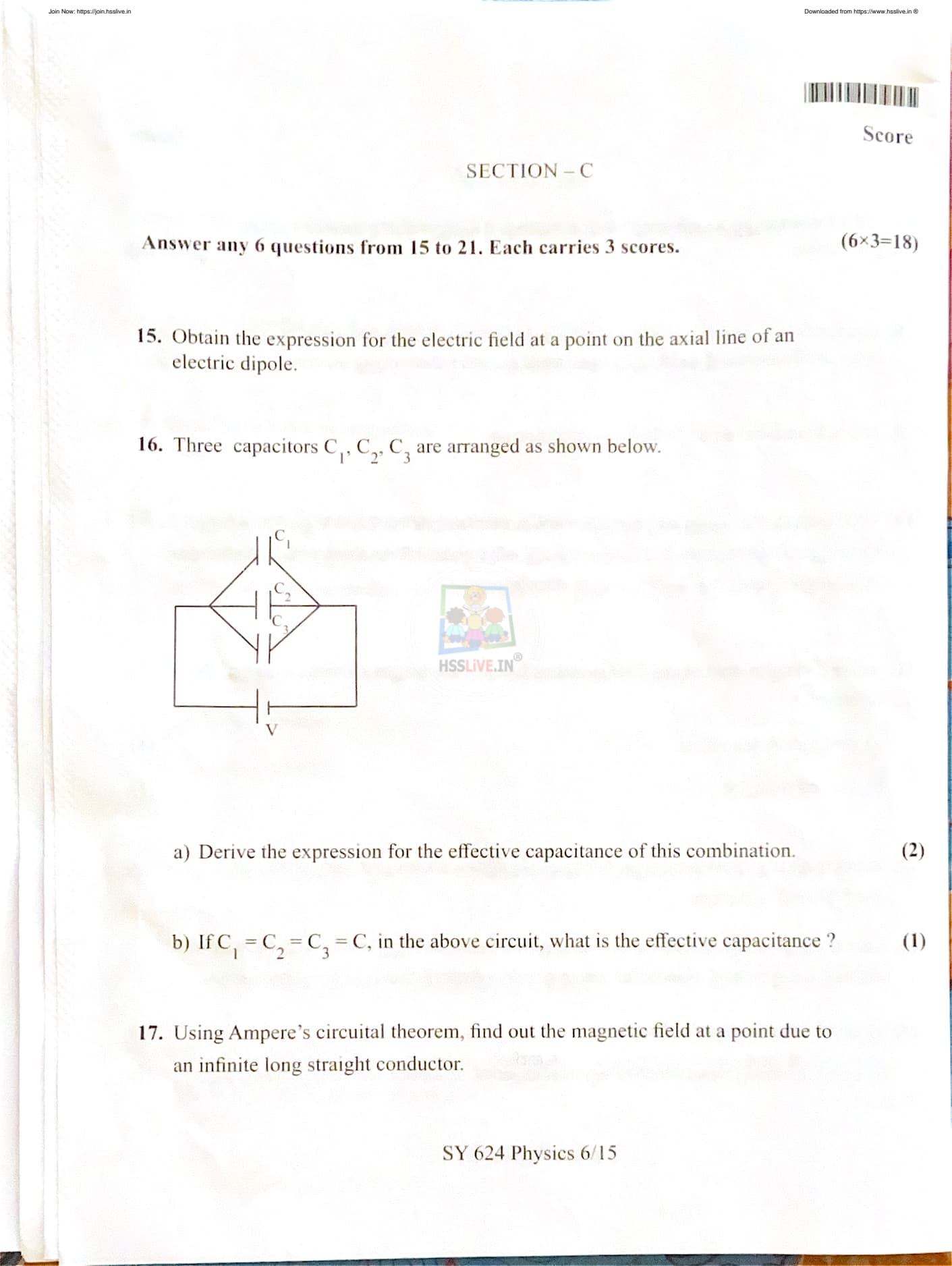
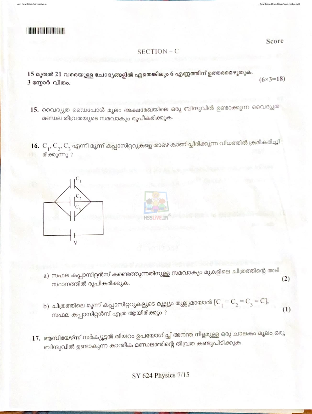
Three capacitors \(C_1, C_2, C_3\) are arranged as shown in the figure.
(a) Derive the expression for the effective capacitance of this combination.
(b) If \(C_1 = C_2 = C_3 = C\), find the effective capacitance.

View Solution
Step 1: Understanding the Circuit Arrangement.
From the given diagram, it is observed that the capacitors \(C_1\), \(C_2\), and \(C_3\) are connected between the same two junction points of the circuit. Hence, all three capacitors are connected in parallel with each other across the applied voltage \(V\).
Step 2: Property of Parallel Combination of Capacitors.
In a parallel combination:
- The potential difference across each capacitor is the same.
- The total or effective capacitance is equal to the sum of individual capacitances.
Step 3: Expression for Charge on Each Capacitor.
Let the potential difference across the combination be \(V\).
Then, the charge on each capacitor is:
\[ Q_1 = C_1 V,\quad Q_2 = C_2 V,\quad Q_3 = C_3 V \]
Step 4: Total Charge of the Combination.
The total charge stored in the combination is the sum of charges on individual capacitors:
\[ Q = Q_1 + Q_2 + Q_3 \] \[ Q = C_1 V + C_2 V + C_3 V \] \[ Q = (C_1 + C_2 + C_3)V \]
Step 5: Definition of Effective Capacitance.
If \(C_{eff}\) is the effective capacitance of the combination, then:
\[ Q = C_{eff} V \]
Step 6: Expression for Effective Capacitance.
Comparing the above equations, we get:
\[ C_{eff} = C_1 + C_2 + C_3 \]
(b) Case when \(C_1 = C_2 = C_3 = C\)
Step 7: Substitution of Equal Capacitances.
If all the capacitors have equal capacitance \(C\), then:
\[ C_{eff} = C + C + C \] \[ C_{eff} = 3C \]
Step 8: Final Answer.
Thus, the effective capacitance of the given combination is:
\[ \boxed{C_{eff} = C_1 + C_2 + C_3} \]
and for \(C_1 = C_2 = C_3 = C\):
\[ \boxed{C_{eff} = 3C} \]
Quick Tip: For capacitors connected in parallel, the effective capacitance is always greater than the largest individual capacitance.
Using Ampere’s circuital theorem, find out the magnetic field at a point due to an infinite long straight conductor.
View Solution
Step 1: Statement of Ampere’s Circuital Theorem.
Ampere’s circuital theorem states that the line integral of the magnetic field around any closed path is equal to \( \mu_0 \) times the total current enclosed by the path. Mathematically,
\[ \oint \vec{B} \cdot d\vec{l} = \mu_0 I \]
Step 2: Physical Situation and Assumptions.
Consider an infinitely long straight conductor carrying a steady current \( I \).
Let \( P \) be a point at a distance \( r \) from the conductor. Due to symmetry, the magnetic field produced is the same at all points equidistant from the wire and acts tangentially to a circle centered on the conductor.
Step 3: Choice of Amperian Loop.
Choose a circular Amperian loop of radius \( r \) with the conductor passing through its center.
At every point on this loop, the magnetic field \( B \) has the same magnitude and is parallel to the element \( d\vec{l} \).
Step 4: Application of Ampere’s Law.
Since \( \vec{B} \) is parallel to \( d\vec{l} \), we have:
\[ \oint \vec{B} \cdot d\vec{l} = \oint B \, dl \] \[ = B \oint dl \] \[ = B (2\pi r) \]
According to Ampere’s circuital theorem:
\[ B (2\pi r) = \mu_0 I \]
Step 5: Expression for Magnetic Field.
Solving for \( B \):
\[ B = \frac{\mu_0 I}{2\pi r} \]
Step 6: Direction of Magnetic Field.
The direction of the magnetic field is given by the right-hand thumb rule.
If the thumb of the right hand points in the direction of current, the curled fingers give the direction of the magnetic field lines around the conductor.
Final Expression.
Thus, the magnetic field at a distance \( r \) from an infinitely long straight current-carrying conductor is:
\[ \boxed{B = \frac{\mu_0 I}{2\pi r}} \]
Quick Tip: The magnetic field around a straight current-carrying conductor forms concentric circular loops centered on the wire.
Compare the magnetic susceptibility and magnetic permeability of diamagnetic, paramagnetic and ferromagnetic substances.
View Solution
Magnetic materials are classified into diamagnetic, paramagnetic, and ferromagnetic substances based on their response to an external magnetic field.
Their behaviour can be compared on the basis of magnetic susceptibility (\( \chi \)) and magnetic permeability (\( \mu \)).
Diamagnetic Substances:
Diamagnetic substances are weakly repelled by an external magnetic field.
The magnetic susceptibility of diamagnetic materials is small and negative, i.e., \( \chi < 0 \).
Their magnetic permeability is slightly less than that of free space, i.e., \( \mu < \mu_0 \).
Examples include copper, silver, gold, bismuth, and water.
Paramagnetic Substances:
Paramagnetic substances are weakly attracted by an external magnetic field.
Their magnetic susceptibility is small and positive, i.e., \( \chi > 0 \).
The magnetic permeability of paramagnetic materials is slightly greater than that of free space, i.e., \( \mu > \mu_0 \).
Examples include aluminium, platinum, chromium, and manganese.
Ferromagnetic Substances:
Ferromagnetic substances are strongly attracted by an external magnetic field.
They have a very large positive magnetic susceptibility, i.e., \( \chi \gg 0 \).
Their magnetic permeability is much greater than that of free space, i.e., \( \mu \gg \mu_0 \).
Examples include iron, cobalt, nickel, and their alloys.
Thus, diamagnetic substances show negative susceptibility, paramagnetic substances show small positive susceptibility, and ferromagnetic substances show very large positive susceptibility.
Quick Tip: The magnitude and sign of magnetic susceptibility help distinguish diamagnetic, paramagnetic, and ferromagnetic materials.
With the help of neat diagram explain reflection of plane wave using Huygen’s principle.
View Solution
Huygen’s principle states that every point on a wavefront acts as a source of secondary wavelets which spread out in all directions with the same speed as the wave.
The new wavefront at any later time is the forward envelope of these secondary wavelets.
To explain reflection of a plane wave using Huygen’s principle, consider a plane wavefront incident on a plane reflecting surface.
Let \( AB \) be the incident plane wavefront striking the reflecting surface \( XY \).
According to Huygen’s principle, each point on the wavefront \( AB \) acts as a source of secondary wavelets.
When the wavefront reaches the reflecting surface, the points on the surface become sources of reflected secondary wavelets.
The reflected wavefront \( CD \) is obtained by drawing a tangent to these secondary wavelets in the reflected direction.
This reflected wavefront makes the same angle with the reflecting surface as the incident wavefront.
Thus, the angle of incidence is equal to the angle of reflection, which confirms the law of reflection.
This explanation using Huygen’s principle shows that reflection of a plane wave obeys the laws of reflection.
Quick Tip: Huygen’s principle explains wave phenomena like reflection by considering wavefronts and secondary wavelets.
Draw the graph showing the variation of photoelectric current with intensity of light.
View Solution
Step 1: Understanding Photoelectric Current.
Photoelectric current is the flow of electrons emitted from a metal surface when light of frequency greater than the threshold frequency falls on it. The magnitude of photoelectric current depends on the number of photoelectrons emitted per second.
Step 2: Role of Intensity of Light.
The intensity of light refers to the number of photons incident per unit area per unit time. When the intensity of incident light increases, more photons strike the metal surface every second. This results in the emission of a greater number of photoelectrons.
Step 3: Relationship between Intensity and Current.
For a fixed frequency of incident light (greater than threshold frequency) and fixed potential, the photoelectric current increases linearly with an increase in intensity of light. This shows that photoelectric current is directly proportional to the intensity of incident radiation.
Step 4: Nature of the Graph.
The graph between photoelectric current and intensity of light is a straight line passing through the origin, indicating a linear relationship.
Graph Description:
X-axis: Intensity of incident light
Y-axis: Photoelectric current
Nature: Straight line through origin
Quick Tip: Increasing light intensity increases photoelectric current but does not affect the kinetic energy of photoelectrons.
The work function of caesium is 2.14 eV. Find the threshold frequency for caesium.
(Given: \( h = 6.63 \times 10^{-34} \, Js \))
View Solution
Step 1: Meaning of Threshold Frequency.
Threshold frequency is the minimum frequency of incident radiation required to just eject electrons from the surface of a metal without imparting any kinetic energy to them. It is related to the work function of the metal.
Step 2: Formula Used.
The relationship between work function and threshold frequency is given by:
\[ \phi = h \nu_0 \]
where \( \phi \) is the work function, \( h \) is Planck’s constant, and \( \nu_0 \) is the threshold frequency.
Step 3: Conversion of Work Function into Joules.
Given work function of caesium:
\[ \phi = 2.14 \, eV \]
Since \( 1 \, eV = 1.6 \times 10^{-19} \, J \),
\[ \phi = 2.14 \times 1.6 \times 10^{-19} \] \[ \phi = 3.424 \times 10^{-19} \, J \]
Step 4: Calculation of Threshold Frequency.
\[ \nu_0 = \frac{\phi}{h} \] \[ \nu_0 = \frac{3.424 \times 10^{-19}}{6.63 \times 10^{-34}} \] \[ \nu_0 \approx 5.17 \times 10^{14} \, Hz \]
Step 5: Final Answer.
The threshold frequency for caesium is \( 5.17 \times 10^{14} \, Hz \).
Quick Tip: Threshold frequency depends only on the nature of the metal and not on the intensity of incident light.
Explain the working of a full wave rectifier having two diodes by drawing the circuit diagram.
View Solution
Step 1: Meaning of Full Wave Rectifier.
A full wave rectifier is an electronic circuit that converts alternating current (AC) into direct current (DC) by allowing current to flow through the load during both the positive and negative half cycles of the input AC signal.
Step 2: Construction of Two-Diode Full Wave Rectifier.
A full wave rectifier using two diodes consists of:
- A centre-tapped transformer
- Two diodes \(D_1\) and \(D_2\)
- A load resistance \(R_L\)
The centre tap of the transformer is connected to one end of the load resistance, while the two diodes are connected to the opposite ends of the secondary winding.
Step 3: Circuit Diagram (Description).
In the circuit, each diode is connected to one half of the secondary winding of the centre-tapped transformer. The output is taken across the load resistance \(R_L\). During operation, only one diode conducts at a time depending on the polarity of the input voltage.
Step 4: Working During Positive Half Cycle.
When the upper end of the transformer secondary becomes positive with respect to the centre tap, diode \(D_1\) is forward biased and conducts, while diode \(D_2\) is reverse biased and does not conduct.
As a result, current flows through diode \(D_1\), the load resistance \(R_L\), and back to the transformer through the centre tap. A positive voltage appears across the load.
Step 5: Working During Negative Half Cycle.
During the negative half cycle, the lower end of the secondary winding becomes positive with respect to the centre tap. Now diode \(D_2\) is forward biased and conducts, while diode \(D_1\) becomes reverse biased.
Current again flows through the load resistance \(R_L\) in the same direction as before. Thus, the output across the load remains unidirectional.
Step 6: Nature of Output.
Since both halves of the input AC signal are utilized, the output voltage across the load consists of pulsating DC with frequency twice that of the input AC supply.
Step 7: Advantages of Full Wave Rectifier.
- Higher rectification efficiency than half wave rectifier
- Better transformer utilization
- Lower ripple factor
Step 8: Conclusion.
Thus, a full wave rectifier using two diodes converts AC into DC by rectifying both half cycles of the input signal, providing a smoother and more efficient DC output.
Quick Tip: In a two-diode full wave rectifier, each diode conducts alternately, but the current through the load always flows in the same direction.
Draw the equipotential surface around a point charge.
View Solution
Step 1: Meaning of Equipotential Surface.
An equipotential surface is a surface on which the electric potential is the same at every point. No work is done in moving a test charge from one point to another on this surface.
Step 2: Equipotential Surface Around a Point Charge.
For a point charge, the electric potential depends only on the distance from the charge and not on the direction. Hence, all points located at the same distance from the point charge have equal potential.
Step 3: Shape of the Equipotential Surface.
The equipotential surfaces around a point charge are concentric spherical surfaces with the point charge at the centre. In a two-dimensional diagram, these surfaces appear as concentric circles around the point charge.
Step 4: Important Property.
The electric field lines are always perpendicular to the equipotential surfaces. As we move closer to the point charge, the equipotential surfaces come closer, showing that the electric field strength increases.
Quick Tip: Closer spacing of equipotential surfaces indicates a stronger electric field.
Derive the expression for electric potential at any point due to an electric dipole.
View Solution
Step 1: Electric Dipole Configuration.
An electric dipole consists of two equal and opposite charges \( +q \) and \( -q \) separated by a small distance \( 2a \). The midpoint of the dipole is taken as the origin. Let point \( P \) be at a distance \( r \) from the centre, making an angle \( \theta \) with the dipole axis.
Step 2: Electric Potential Due to Individual Charges.
The electric potential at point \( P \) due to charge \( +q \) is:
\[ V_{+} = \frac{1}{4\pi\varepsilon_0}\frac{q}{r_1} \]
The electric potential due to charge \( -q \) is:
\[ V_{-} = -\frac{1}{4\pi\varepsilon_0}\frac{q}{r_2} \]
Step 3: Net Electric Potential at Point \( P \).
The total electric potential is the algebraic sum of the potentials due to both charges:
\[ V = \frac{1}{4\pi\varepsilon_0} \left( \frac{q}{r_1} - \frac{q}{r_2} \right) \]
Step 4: Approximation for Distant Point.
For \( r \gg a \), the distances can be written as:
\[ r_1 \approx r - a\cos\theta, \quad r_2 \approx r + a\cos\theta \]
On simplifying using binomial approximation, we get:
\[ V = \frac{1}{4\pi\varepsilon_0}\frac{2aq\cos\theta}{r^2} \]
Step 5: Expression in Terms of Dipole Moment.
The electric dipole moment \( p \) is defined as:
\[ p = 2aq \]
Substituting this value, the expression becomes:
\[ V = \frac{1}{4\pi\varepsilon_0}\frac{p\cos\theta}{r^2} \]
Final Expression.
Thus, the electric potential at any point due to an electric dipole is:
\[ \boxed{V = \frac{1}{4\pi\varepsilon_0}\frac{p\cos\theta}{r^2}} \]
Quick Tip: Electric potential due to a dipole depends on the angle \( \theta \) between the point and the dipole axis.
State Kirchhoff’s junction rule.
View Solution
Kirchhoff’s junction rule states that at any junction or node in an electrical circuit, the algebraic sum of currents is zero.
This means that the total current entering a junction is exactly equal to the total current leaving the junction.
Mathematically, the junction rule is expressed as:
\[ \sum I_{entering} = \sum I_{leaving} \]
This law is based on the principle of conservation of electric charge.
Since electric charge cannot be created or destroyed, no charge accumulates at a junction in a steady-state circuit.
Quick Tip: Kirchhoff’s junction rule is a direct consequence of the conservation of electric charge.
Obtain the balancing condition of Wheatstone’s bridge with the help of a diagram.
View Solution
A Wheatstone bridge is an electrical arrangement used to determine an unknown resistance accurately.
It consists of four resistances arranged in a diamond shape, a galvanometer, and a source of emf.
Let the four resistances of the bridge be \( P \), \( Q \), \( R \), and \( S \).
A galvanometer is connected between the junctions of resistances \( P \)–\( Q \) and \( R \)–\( S \).
When the Wheatstone bridge is balanced, no current flows through the galvanometer.
This implies that the potential difference across the galvanometer is zero.
Applying Kirchhoff’s laws to the circuit, the balancing condition of the Wheatstone bridge is obtained as:
\[ \frac{P}{Q} = \frac{R}{S} \]
This condition shows that the ratio of the resistances in one pair of adjacent arms is equal to the ratio of the resistances in the other pair of adjacent arms.
When this condition is satisfied, the galvanometer shows zero deflection, and the bridge is said to be balanced.
The Wheatstone bridge is widely used because it provides accurate measurement of unknown resistances.
Quick Tip: A Wheatstone bridge is balanced when no current flows through the galvanometer.
What is self induction?
View Solution
Step 1: Definition of Self Induction.
Self induction is the phenomenon in which a changing electric current in a coil induces an electromotive force (emf) in the same coil. This induced emf opposes the change in current that produces it, in accordance with Lenz’s law.
Step 2: Physical Explanation.
When an electric current flows through a coil, it produces a magnetic field around it. If the current changes with time, the magnetic flux linked with the coil also changes. This change in magnetic flux induces an emf in the same coil. Since the emf is produced in the same coil due to its own current, the phenomenon is called self induction.
Step 3: Mathematical Expression.
The self-induced emf is given by the relation:
\[ e = -L \frac{dI}{dt} \]
where \( L \) is the coefficient of self inductance and \( \frac{dI}{dt} \) is the rate of change of current. The negative sign indicates that the induced emf opposes the change in current.
Step 4: Importance of Self Induction.
Self induction prevents sudden changes in current in electrical circuits. It plays a vital role in electrical devices such as inductors, chokes, transformers, relays, and electric motors.
Quick Tip: Self induction occurs due to a change in current within the same coil.
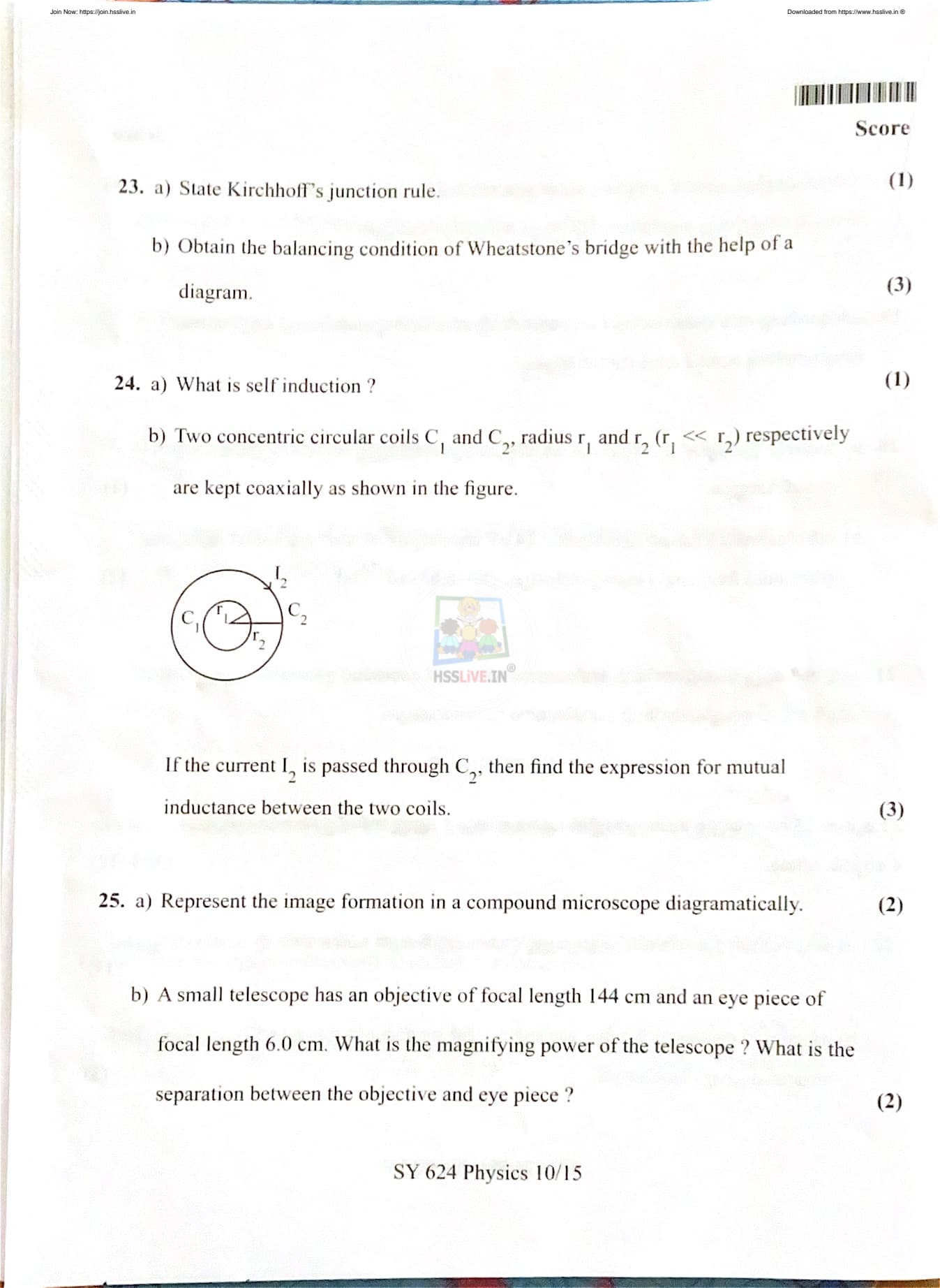
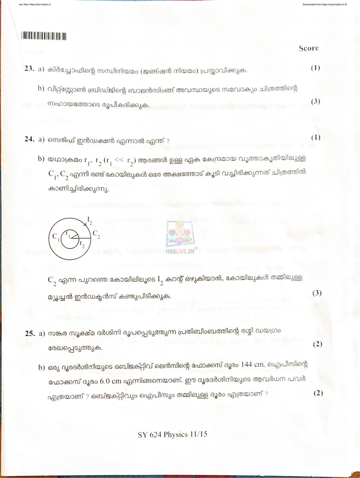
Two concentric circular coils \( C_1 \) and \( C_2 \) of radii \( r_1 \) and \( r_2 \) respectively (\( r_1 \ll r_2 \)) are kept coaxially as shown in the figure. If the current \( I_2 \) is passed through coil \( C_2 \), find the expression for mutual inductance between the two coils.

View Solution
Step 1: Arrangement of the Coils.
Two circular coils \( C_1 \) and \( C_2 \) are placed concentrically with a common axis. The radius of the inner coil \( C_1 \) is much smaller than that of the outer coil \( C_2 \). A current \( I_2 \) flows through the outer coil \( C_2 \).
Step 2: Magnetic Field Due to Outer Coil.
The magnetic field at the center of a circular coil of radius \( r_2 \) carrying current \( I_2 \) is given by:
\[ B = \frac{\mu_0 I_2}{2 r_2} \]
Since \( r_1 \ll r_2 \), the magnetic field over the entire area of the inner coil \( C_1 \) can be considered uniform.
Step 3: Magnetic Flux Linked with Inner Coil.
The magnetic flux linked with coil \( C_1 \) is given by:
\[ \Phi = B \times A \] \[ \Phi = \frac{\mu_0 I_2}{2 r_2} \times \pi r_1^2 \]
Step 4: Expression for Mutual Inductance.
Mutual inductance \( M \) is defined as the magnetic flux linked with one coil per unit current flowing in the other coil. Hence,
\[ M = \frac{\Phi}{I_2} \] \[ M = \frac{\mu_0 \pi r_1^2}{2 r_2} \]
Step 5: Final Result.
The mutual inductance between the two concentric circular coils is given by:
\[ \boxed{M = \frac{\mu_0 \pi r_1^2}{2 r_2}} \] Quick Tip: Mutual inductance depends on the geometry of the coils and the magnetic field produced by one coil linking the other.
Represent the image formation in a compound microscope diagrammatically.
View Solution
Step 1: Construction of a Compound Microscope.
A compound microscope consists of two convex lenses: an objective lens of very small focal length and an eyepiece (ocular) of comparatively larger focal length. The object is placed just beyond the focal point of the objective lens.
Step 2: Formation of the Intermediate Image.
The objective lens forms a real, inverted, and magnified image of the object. This image is formed between the objective and the eyepiece and lies within the focal length of the eyepiece.
Step 3: Formation of the Final Image.
The eyepiece acts as a simple microscope. It magnifies the intermediate image further and produces a virtual, inverted, and highly magnified final image. The final image is usually formed at the least distance of distinct vision.
Step 4: Diagrammatic Explanation.
In the ray diagram of a compound microscope, the objective produces a real inverted image which serves as the object for the eyepiece. The eyepiece then produces a virtual enlarged image for the observer.
Quick Tip: In a compound microscope, magnification occurs in two stages: first by the objective and then by the eyepiece.
A small telescope has an objective of focal length 144 cm and an eye piece of focal length 6.0 cm. What is the magnifying power of the telescope? What is the separation between the objective and eye piece?
View Solution
Given:
Focal length of objective, \( f_o = 144 \, cm \)
Focal length of eyepiece, \( f_e = 6.0 \, cm \)
Step 1: Magnifying Power of the Telescope.
For a telescope in normal adjustment, the magnifying power is given by:
\[ M = \frac{f_o}{f_e} \]
Substituting the given values:
\[ M = \frac{144}{6} = 24 \]
Step 2: Separation Between Objective and Eyepiece.
For a telescope in normal adjustment, the separation between the objective and eyepiece is equal to the sum of their focal lengths:
\[ L = f_o + f_e \]
Substituting the values:
\[ L = 144 + 6 = 150 \, cm \]
Step 3: Final Answer.
Magnifying power of the telescope:
\[ \boxed{M = 24} \]
Separation between objective and eyepiece:
\[ \boxed{L = 150 \, cm} \]
Quick Tip: In normal adjustment of a telescope, the final image is formed at infinity and tube length equals the sum of focal lengths.
State whether the following statements are true or false.
(1) Gauss’s law is true for any closed surface, irrespective of its size or shape.
(2) Gauss’s law is based on inverse square dependence on distance as in Coulomb’s law.
View Solution
Statement (1):
Gauss’s law states that the total electric flux through any closed surface depends only on the net charge enclosed by the surface and not on its shape or size. Therefore, it is valid for all closed surfaces.
Answer: True
Statement (2):
Gauss’s law can be derived from Coulomb’s law, which follows the inverse square dependence of electric force (and electric field) on distance. Hence, Gauss’s law is fundamentally based on the inverse square nature of Coulomb’s law.
Answer: True
Quick Tip: Gauss’s law is universally valid for all closed surfaces and is closely related to Coulomb’s inverse square law.
Using Gauss’s law, obtain the expression for electric field due to a uniformly charged infinite plane sheet.
View Solution
Step 1: Physical Description.
Consider an infinite plane sheet uniformly charged with surface charge density \( \sigma \). Due to symmetry, the electric field produced by the sheet is perpendicular to its surface and has the same magnitude on both sides of the sheet.
Step 2: Selection of Gaussian Surface.
Choose a cylindrical Gaussian surface (pillbox) with its flat faces parallel to the plane sheet and of cross-sectional area \(A\). One face lies on one side of the sheet and the other face lies on the opposite side.
Step 3: Electric Flux Through the Gaussian Surface.
The electric field is perpendicular to the plane sheet and hence perpendicular to the flat faces of the cylinder. There is no flux through the curved surface.
Total electric flux through the Gaussian surface is:
\[ \Phi = EA + EA = 2EA \]
Step 4: Charge Enclosed by the Gaussian Surface.
The charge enclosed inside the Gaussian surface is:
\[ q_{enc} = \sigma A \]
Step 5: Application of Gauss’s Law.
According to Gauss’s law:
\[ \Phi = \frac{q_{enc}}{\varepsilon_0} \] \[ 2EA = \frac{\sigma A}{\varepsilon_0} \]
Step 6: Expression for Electric Field.
Cancelling \(A\) from both sides, we get:
\[ E = \frac{\sigma}{2\varepsilon_0} \]
Step 7: Conclusion.
Thus, the electric field due to a uniformly charged infinite plane sheet is constant and independent of the distance from the sheet.
Quick Tip: The electric field due to an infinite plane sheet is uniform and does not depend on distance.
Explain the theory and working of a moving coil galvanometer.
View Solution
Step 1: Principle of Moving Coil Galvanometer.
A moving coil galvanometer works on the principle that when a current-carrying conductor is placed in a magnetic field, it experiences a torque. This torque causes the coil to rotate, and the amount of rotation is proportional to the current flowing through the coil.
Step 2: Construction.
A rectangular coil of insulated copper wire is wound on a light aluminium frame and placed between the poles of a strong permanent magnet. The magnetic field is made radial by using soft iron pole pieces. The coil is suspended using a fine phosphor bronze spring which provides restoring torque.
Step 3: Theory of Operation.
When current \( I \) flows through the coil, each side of the coil experiences a magnetic force. These forces act in opposite directions, producing a torque that tends to rotate the coil. The magnetic torque acting on the coil is given by:
\[ \tau_m = nBIA \]
where \( n \) is the number of turns, \( B \) is the magnetic field, \( A \) is the area of the coil, and \( I \) is the current.
Step 4: Restoring Torque.
As the coil rotates, the suspension spring provides a restoring torque proportional to the angle of deflection \( \theta \):
\[ \tau_r = k\theta \]
where \( k \) is the torsional constant of the spring.
Step 5: Condition of Equilibrium.
At equilibrium, magnetic torque equals restoring torque:
\[ nBIA = k\theta \] \[ \theta \propto I \]
Thus, the deflection of the coil is directly proportional to the current flowing through it.
Step 6: Working.
When current flows through the galvanometer, the coil deflects. The pointer attached to the coil moves over a calibrated scale, indicating the magnitude and direction of the current.
Quick Tip: A radial magnetic field ensures that deflection is directly proportional to current.
How can you convert a galvanometer into a voltmeter?
View Solution
Step 1: Need for Conversion.
A galvanometer is a sensitive instrument that can detect only small currents. To measure potential difference, it must be converted into a voltmeter.
Step 2: Method of Conversion.
A galvanometer is converted into a voltmeter by connecting a high resistance in series with it. This high resistance is called a multiplier.
Step 3: Reason for Using High Resistance.
The high resistance limits the current through the galvanometer, ensuring that only a small current flows even when a large potential difference is applied.
Step 4: Expression for Series Resistance.
If \( G \) is the resistance of the galvanometer, \( I_g \) is the full-scale deflection current, and \( V \) is the maximum voltage to be measured, then the required series resistance \( R \) is:
\[ R = \frac{V}{I_g} - G \]
Step 5: Conclusion.
Thus, by connecting a suitable high resistance in series, a galvanometer can be converted into a voltmeter.
Quick Tip: A voltmeter always has very high resistance.
Write the equation of current sensitivity of a moving coil galvanometer.
View Solution
Step 1: Definition of Current Sensitivity.
Current sensitivity of a moving coil galvanometer is defined as the angular deflection produced per unit current flowing through the galvanometer.
Step 2: Expression for Current Sensitivity.
Current sensitivity is given by:
\[ Current Sensitivity = \frac{\theta}{I} \]
Step 3: Derivation of the Expression.
From the working principle of the galvanometer:
\[ nBIA = k\theta \] \[ \frac{\theta}{I} = \frac{nBA}{k} \]
Step 4: Final Equation.
Thus, the current sensitivity of a moving coil galvanometer is:
\[ \boxed{\frac{\theta}{I} = \frac{nBA}{k}} \]
Quick Tip: Higher number of turns and stronger magnetic field increase current sensitivity.
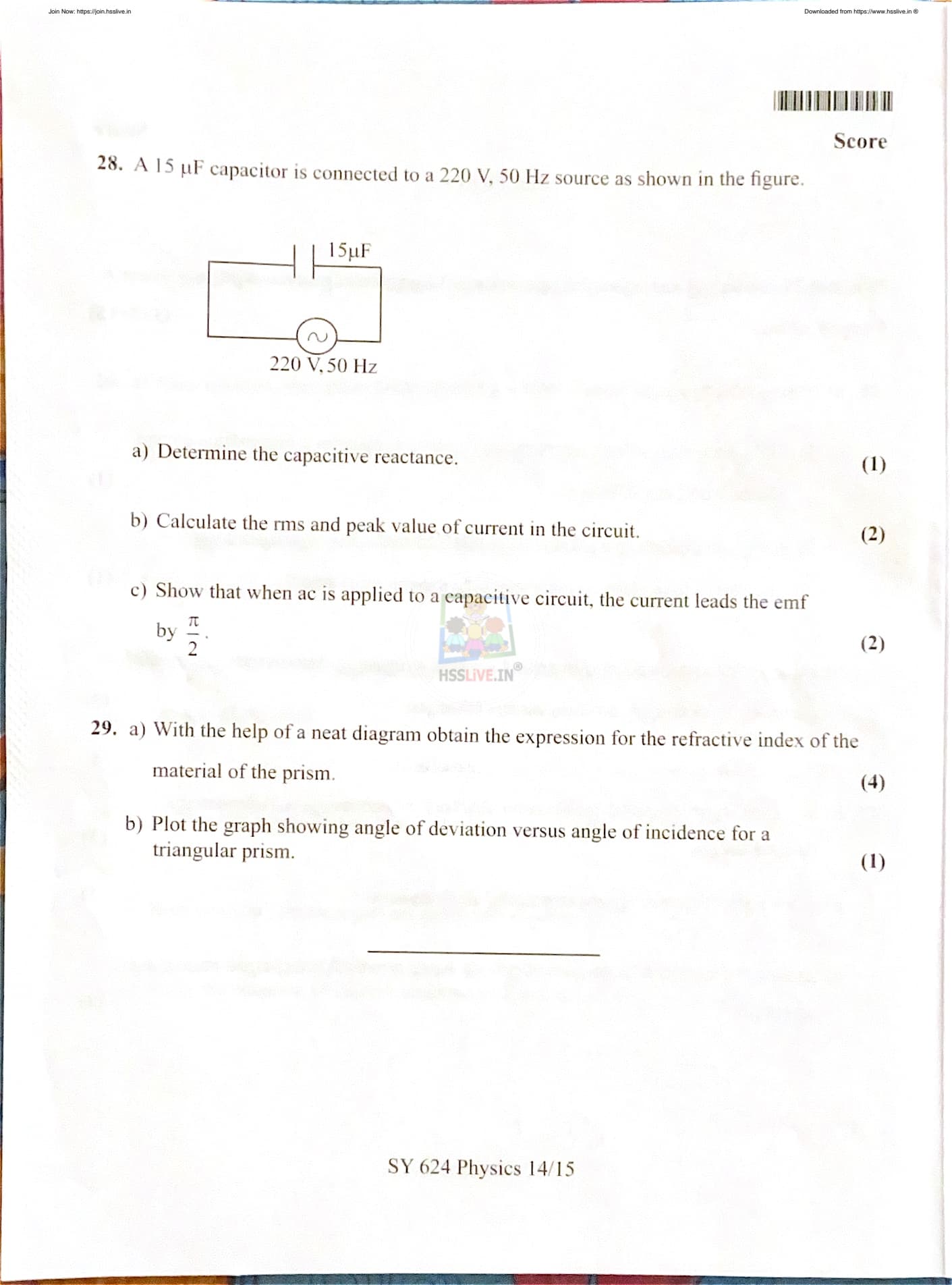
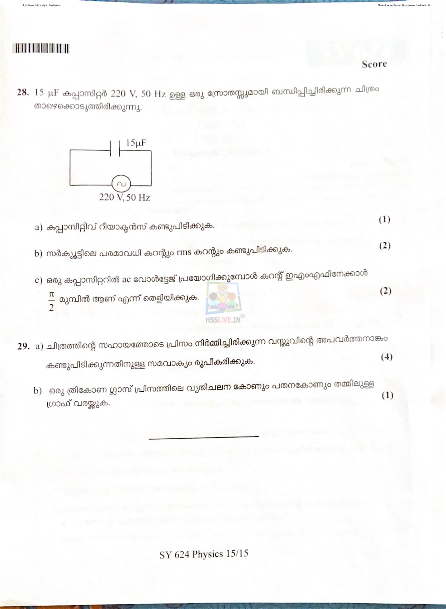
A 15 \(\muF\) capacitor is connected to a 220 V, 50 Hz AC source as shown in the figure.
(a) Determine the capacitive reactance.
(b) Calculate the rms and peak value of current in the circuit.
(c) Show that when AC is applied to a capacitive circuit, the current leads the emf by \(\dfrac{\pi}{2}\).

View Solution
(a) Determination of Capacitive Reactance
Step 1: Given data.
Capacitance, \( C = 15 \muF = 15 \times 10^{-6} F \)
Frequency, \( f = 50 Hz \)
Step 2: Formula for capacitive reactance.
Capacitive reactance is given by:
\[ X_C = \frac{1}{2\pi f C} \]
Step 3: Substitution of values.
\[ X_C = \frac{1}{2\pi \times 50 \times 15 \times 10^{-6}} \] \[ X_C = \frac{1}{4.712 \times 10^{-3}} \] \[ X_C \approx 2122 \, \Omega \]
Thus, the capacitive reactance is \( \boxed{2122 \, \Omega} \).
(b) Calculation of RMS and Peak Current
Step 4: RMS value of voltage.
Given rms voltage, \( V_{rms} = 220 V \)
Step 5: Formula for rms current.
\[ I_{rms} = \frac{V_{rms}}{X_C} \]
Step 6: Substitution of values.
\[ I_{rms} = \frac{220}{2122} \] \[ I_{rms} \approx 0.104 A \]
Step 7: Formula for peak current.
\[ I_0 = \sqrt{2} \, I_{rms} \]
Step 8: Calculation of peak current.
\[ I_0 = \sqrt{2} \times 0.104 \] \[ I_0 \approx 0.147 A \]
Thus,
\[ \boxed{I_{rms} = 0.104 A, \quad I_0 = 0.147 A} \]
(c) Phase Relation Between Current and EMF in a Capacitive Circuit
Step 9: Expression for applied AC voltage.
Let the applied alternating voltage be:
\[ V = V_0 \sin \omega t \]
Step 10: Expression for charge on capacitor.
\[ Q = C V = C V_0 \sin \omega t \]
Step 11: Expression for current.
Current is given by the rate of change of charge:
\[ I = \frac{dQ}{dt} \] \[ I = C V_0 \omega \cos \omega t \] \[ I = I_0 \sin \left(\omega t + \frac{\pi}{2}\right) \]
Step 12: Conclusion of phase relationship.
The above equation shows that current reaches its maximum value \(\frac{\pi}{2}\) radians earlier than the voltage. Hence, the current leads the applied emf by a phase angle of \(\frac{\pi}{2}\).
Quick Tip: In a purely capacitive AC circuit, current always leads the voltage by \(90^\circ\) or \(\dfrac{\pi}{2}\) radians.
With the help of a neat diagram obtain the expression for the refractive index of the material of the prism.
View Solution
Step 1: Refraction through a Prism.
Consider a triangular prism of refracting angle \( A \). A ray of light is incident on one face of the prism and emerges from the other face after refraction. Let the angle of incidence be \( i \), angle of refraction inside the prism be \( r_1 \), angle of emergence be \( e \), and angle of refraction at the second face be \( r_2 \).
Step 2: Relation between Angles inside the Prism.
From the geometry of the prism:
\[ r_1 + r_2 = A \]
The angle of deviation \( \delta \) is given by:
\[ \delta = i + e - A \]
Step 3: Condition of Minimum Deviation.
At the condition of minimum deviation \( \delta_m \), the path of light through the prism is symmetrical. Hence:
\[ i = e \quad and \quad r_1 = r_2 = \frac{A}{2} \]
From the deviation equation:
\[ \delta_m = 2i - A \] \[ i = \frac{A + \delta_m}{2} \]
Step 4: Applying Snell’s Law.
Using Snell’s law at the first face of the prism:
\[ \mu = \frac{\sin i}{\sin r_1} \]
Substituting the values of \( i \) and \( r_1 \):
\[ \mu = \frac{\sin \left( \frac{A + \delta_m}{2} \right)}{\sin \left( \frac{A}{2} \right)} \]
Final Expression.
Thus, the refractive index of the material of the prism is:
\[ \boxed{\mu = \frac{\sin \left( \frac{A + \delta_m}{2} \right)}{\sin \left( \frac{A}{2} \right)}} \]
Quick Tip: The refractive index of a prism can be determined experimentally by measuring the angle of minimum deviation.
Plot the graph showing angle of deviation versus angle of incidence for a triangular prism.
View Solution
Step 1: Nature of the Graph.
When a ray of light passes through a triangular prism, the angle of deviation \( \delta \) varies with the angle of incidence \( i \). Initially, as the angle of incidence increases, the angle of deviation decreases.
Step 2: Minimum Deviation.
At a particular angle of incidence, the angle of deviation becomes minimum. This angle is known as the angle of minimum deviation \( \delta_m \). At this point, the ray passes symmetrically through the prism.
Step 3: Further Variation.
Beyond the angle of minimum deviation, if the angle of incidence is increased further, the angle of deviation starts increasing again.
Step 4: Shape of the Graph.
The graph between angle of deviation \( \delta \) (on the y-axis) and angle of incidence \( i \) (on the x-axis) is a smooth curve with a clear minimum point.
Step 5: Conclusion.
The minimum point on the graph represents the condition of minimum deviation, which is used to determine the refractive index of the prism material.
Quick Tip: The graph of deviation versus incidence is symmetric about the angle corresponding to minimum deviation.


Comments