TS PGECET 2026 Metallurgical Engineering (MT) Question Paper is available for download here. JNTU Hyderabad on behalf of Telangana Council of Higher Education (TGCHE) conducted TS PGECET 2026 MT exam on May 30 in Shift 2 from 2 PM to 4 PM. TS PGECET MT Question Paper consists of 120 questions for 120 marks to be attempted in 2 hours.
- TS PGECET MT Question Paper 2026 is divided into 2 sections- Engineering Mathematics with 10 questions and Metallurgical Engineering domain with 110 questions.
- Each questions carries 1 mark each and there is no negative marking for incorrect answers.
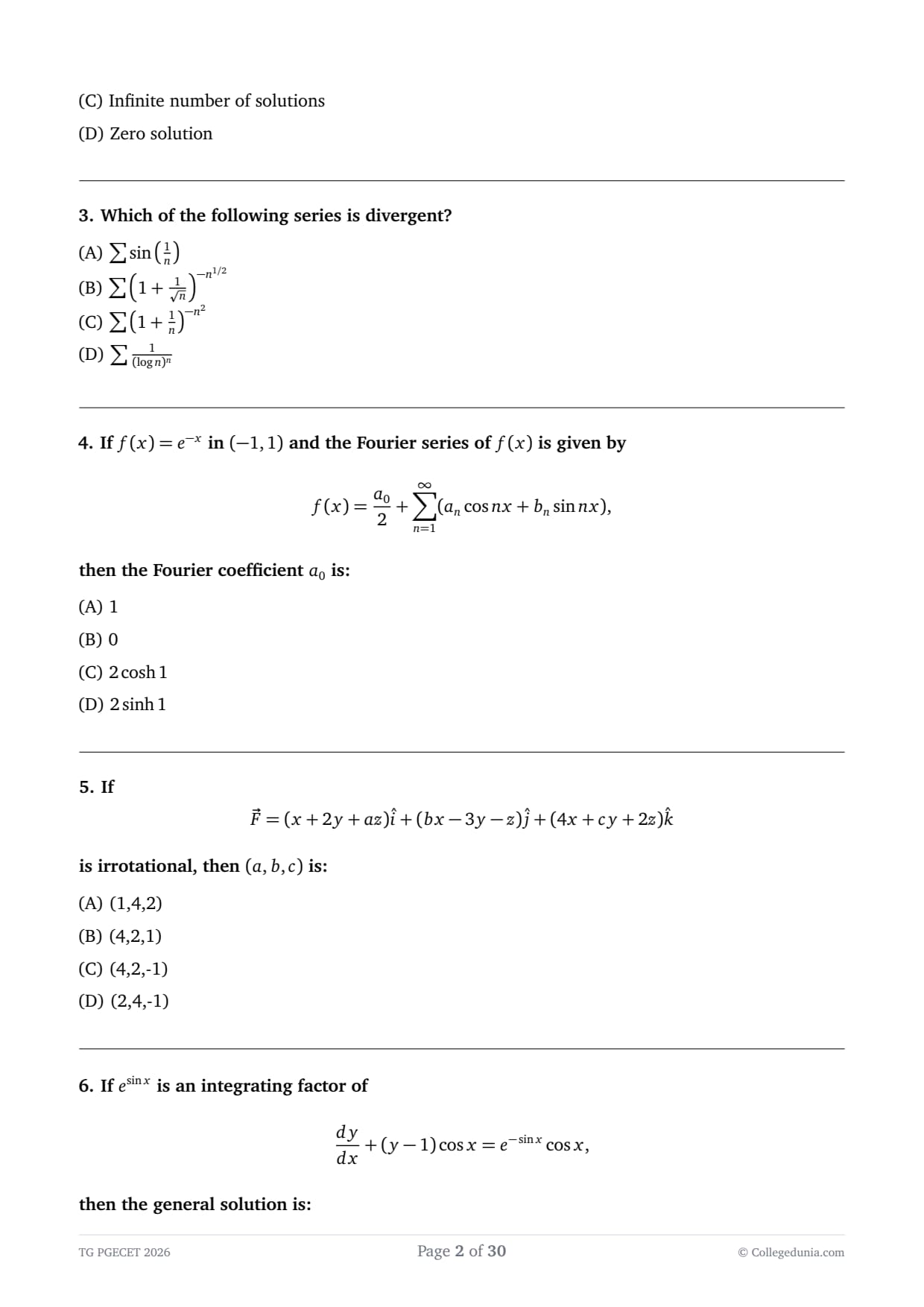
Candidates can download TS PGECET 2026 MT Question Paper with Answer Key and Solution PDF from links provided below.
TS PGECET 2026 MT Question Paper with Solution PDF
| TS PGECET MT Question Paper 2026 | Download PDF | Check Solutions |
If
\[ \begin{bmatrix} 1 \\ 1 \end{bmatrix} \] is an eigenvector of the matrix \[ \begin{bmatrix} m & 3 \\ 3 & m \end{bmatrix} \] then the corresponding eigenvalue is:View Solution
Concept:
If \(\vec{x}\) is an eigenvector of matrix \(A\), then: \[ A\vec{x}=\lambda \vec{x} \]
This means multiplication of matrix with vector gives a scalar multiple of the same vector.
Step 1: Write matrix-vector multiplication.
\[ A\vec{x}= \begin{bmatrix} m & 3 \\ 3 & m \end{bmatrix} \begin{bmatrix} 1 \\ 1 \end{bmatrix} \]
Now multiply:
First row: \[ m(1)+3(1)=m+3 \]
Second row: \[ 3(1)+m(1)=m+3 \]
So,
Step 2: Compare with eigenvector form. \[ \begin{bmatrix} m+3 \\ m+3 \end{bmatrix} = (m+3) \begin{bmatrix} 1 \\ 1 \end{bmatrix} \] Thus eigenvalue: \[ \lambda = m+3 \] Quick Tip: If all components scale equally after multiplication, that scale factor is the eigenvalue.
The system of equations \[ x-2y+3z=6,\quad 3x+y-4z=-7,\quad 5x-3y+2z=5 \]
has:
View Solution
Concept:
For a system \(AX=B\):
- If \(\det(A)\neq 0\) → unique solution
- If \(\det(A)=0\) → check consistency → infinite or no solution
Step 1: Write coefficient matrix.
| 1 | -2 | 3 |
| 3 | 1 | -4 |
| 5 | -3 | 2 |
Step 2: Check determinant.
Expanding:
| 1 | -4 |
| -3 | 2 |
| 3 | -4 |
| 5 | 2 |
| 3 | 1 |
| 5 | -3 |
\[ =1(2-12)+2(6+20)+3(-9-5) \]
\[ =-10+52-42=0 \]
So system is dependent.
Step 3: Check consistency.
Since equations reduce to same plane relation, system is consistent and dependent.
\[ \Rightarrow Infinite solutions \] Quick Tip: If \(\det(A)=0\), system may still be consistent → check rank.
Which of the following series is divergent?
View Solution
Concept:
A series diverges if its general term does not go to zero fast enough or behaves like a divergent comparison series.
Step 1: Analyze option (A).
For small \(x\): \[ \sin x \approx x \]
So: \[ \sin\left(\frac{1}{n}\right)\approx \frac{1}{n} \]
Step 2: Compare with harmonic series.
\[ \sum \frac{1}{n} diverges \]
So (A) diverges.
Step 3: Check other options briefly.
(B), (C), (D) all behave like rapidly decaying exponential-type series → convergent.
\[ \Rightarrow Only (A) diverges \] Quick Tip: If \(\sin(1/n)\) appears, always compare with \(1/n\).
If \(f(x)=e^{-x}\) in \((-1,1)\) and the Fourier series of \(f(x)\) is given by \[ f(x)=\frac{a_0}{2}+\sum_{n=1}^{\infty}(a_n\cos nx+b_n\sin nx), \]
then the Fourier coefficient \(a_0\) is:
View Solution
Concept:
For a function defined on \((-L,L)\), the Fourier coefficient \(a_0\) is given by: \[ a_0=\frac{1}{L}\int_{-L}^{L} f(x)\,dx \]
Here \(L=1\), so: \[ a_0=\int_{-1}^{1} e^{-x}\,dx \]
Step 1: Write the integral.
\[ a_0=\int_{-1}^{1} e^{-x}\,dx \]
Step 2: Integrate.
\[ \int e^{-x}dx=-e^{-x} \]
So, \[ a_0=\left[-e^{-x}\right]_{-1}^{1} \]
Step 3: Apply limits.
\[ a_0=-(e^{-1})-(-e^{1}) \]
\[ a_0=e-e^{-1} \]
Step 4: Rewrite in hyperbolic form.
\[ e-e^{-1}=2\sinh 1 \]
\[ \Rightarrow a_0=2\sinh 1 \] Quick Tip: Use identities: \[ \sinh x=\frac{e^x-e^{-x}}{2} \] to simplify Fourier integrals.
If \[ \vec{F}=(x+2y+az)\hat{i}+(bx-3y-z)\hat{j}+(4x+cy+2z)\hat{k} \]
is irrotational, then \((a,b,c)\) is:
View Solution
Concept:
A vector field is irrotational if: \[ \nabla \times \vec{F}=0 \]
So all components of curl must be zero.
Step 1: Write components.
\[ P=x+2y+az,\quad Q=bx-3y-z,\quad R=4x+cy+2z \]
Step 2: Compute curl components.
\[ \nabla \times \vec{F}= \begin{vmatrix} \hat{i} & \hat{j} & \hat{k}
\frac{\partial}{\partial x} & \frac{\partial}{\partial y} & \frac{\partial}{\partial z}
P & Q & R \end{vmatrix} \]
For \(\hat{i}\) component: \[ \frac{\partial R}{\partial y}-\frac{\partial Q}{\partial z}=c-(-1)=c+1=0 \Rightarrow c=-1 \]
For \(\hat{j}\) component: \[ \frac{\partial R}{\partial x}-\frac{\partial P}{\partial z}=4-a=0 \Rightarrow a=4 \]
For \(\hat{k}\) component: \[ \frac{\partial Q}{\partial x}-\frac{\partial P}{\partial y}=b-2=0 \Rightarrow b=2 \]
\[ \Rightarrow (a,b,c)=(4,2,-1) \] Quick Tip: For irrotational fields, compute curl component-wise and equate to zero.
If \(e^{\sin x}\) is an integrating factor of \[ \frac{dy}{dx}+(y-1)\cos x=e^{-\sin x}\cos x, \]
then the general solution is:
View Solution
Concept:
A linear differential equation: \[ \frac{dy}{dx}+Py=Q \]
has integrating factor: \[ IF=e^{\int Pdx} \]
Step 1: Rewrite equation.
\[ \frac{dy}{dx}+y\cos x=\cos x+e^{-\sin x}\cos x \]
So, \[ P=\cos x \]
Given IF: \[ IF=e^{\sin x} \]
Step 2: Multiply by IF.
\[ e^{\sin x}\frac{dy}{dx}+y e^{\sin x}\cos x = e^{\sin x}\cos x + \cos x \]
Left side becomes: \[ \frac{d}{dx}(y e^{\sin x}) \]
Step 3: Integrate both sides.
\[ \frac{d}{dx}(y e^{\sin x}) = e^{\sin x}\cos x + \cos x \]
\[ y e^{\sin x}=\int e^{\sin x}\cos x\,dx+\int \cos x\,dx \]
\[ = e^{\sin x}+\sin x + C \]
Step 4: Solve for \(y\).
\[ y=(\sin x+e^{\sin x}+C)e^{-\sin x} \] Quick Tip: After multiplying by IF, left side becomes exact derivative.
Find \(L\{t\,u(t-2)\}\).
View Solution
Concept:
Use shifting property: \[ L\{f(t-a)u(t-a)\}=e^{-as}F(s) \]
Step 1: Rewrite function.
\[ t u(t-2)=(t-2+2)u(t-2) \]
\[ =(t-2)u(t-2)+2u(t-2) \]
Step 2: Apply Laplace transform.
\[ L\{(t-2)u(t-2)\}=e^{-2s}\frac{1}{s^2} \]
\[ L\{2u(t-2)\}=2\cdot \frac{e^{-2s}}{s} \]
Step 3: Combine results.
\[ L = e^{-2s}\left(\frac{1}{s^2}+\frac{2}{s}\right) \]
\[ = \frac{e^{-2s}(2s+1)}{s^2} \] Quick Tip: Always split expressions before applying Laplace shifting.
Using Runge-Kutta method, when \(\frac{dy}{dx}=xy+y^{2}\), \(y(0)=1\) is solved by taking \(h=0.1\), then in the usual notation the value of \(k_{1}\) is:
View Solution
Concept:
In Runge-Kutta method (order 4 or standard form), the first step is: \[ k_1 = h f(x_0,y_0) \]
where \[ f(x,y)=xy+y^2 \]
Step 1: Write given values.
\[ x_0=0,\quad y_0=1,\quad h=0.1 \]
Step 2: Compute \(f(x_0,y_0)\).
\[ f(0,1)=0\cdot 1 + 1^2 = 1 \]
Step 3: Compute \(k_1\).
\[ k_1 = h f(x_0,y_0) \]
\[ k_1 = 0.1 \times 1 = 0.1 \]
\[ \boxed{k_1=0.1} \] Quick Tip: In RK method, always compute \(f(x_0,y_0)\) first, then multiply by step size \(h\).
If \(X \sim N(\mu,\sigma^2)\) then:
View Solution
Concept:
For a continuous random variable, probability at a single point is always zero: \[ P(X=a)=0 \]
Normal distribution is a continuous distribution.
Step 1: Use property of continuous distribution.
Since \(X\) is continuous, \[ P(X=\mu)=0 \]
Step 2: Check symmetry (additional insight).
Normal distribution is symmetric about mean: \[ P(X<\mu)=P(X>\mu)=\frac{1}{2} \]
Final Conclusion:
\[ P(X=\mu)=0 \] Quick Tip: In continuous distributions, probability at a point is always zero.
Assertion (A): Spearman rank correlation coefficient is used for ordinal data.
Reason (R): It is based on ranks rather than actual values.
View Solution
Concept:
Spearman rank correlation is a non-parametric measure of correlation used when data is in ranked form (ordinal data).
Step 1: Check Assertion (A).
Spearman correlation is used for ordinal (ranked) data: \[ \Rightarrow A is TRUE \]
Step 2: Check Reason (R).
It is defined using ranks instead of actual values: \[ r_s = 1 - \frac{6\sum d^2}{n(n^2-1)} \]
So R is also TRUE.
Step 3: Check explanation link.
Since method is based on ranks, it is suitable for ordinal data.
\[ \Rightarrow R correctly explains A \]
Final Answer: \[ \boxed{(A) Both A and R are true and R is correct explanation} \] Quick Tip: Spearman correlation is preferred when actual numerical values are unreliable but ranks are meaningful.
The figure shows variation of heat capacity with temperature for Nickel (0–800 K). If the curve shows discontinuity at point P, then this is due to:
View Solution
Concept:
Nickel is a ferromagnetic material at low temperature. As temperature increases, it undergoes a transition from ferromagnetic to paramagnetic state at the Curie temperature.
At this point, magnetic ordering disappears, causing a sudden change (discontinuity) in heat capacity curve.
Step 1: Identify physical nature of Nickel.
Nickel is ferromagnetic below Curie temperature: \[ T < T_C \Rightarrow ordered magnetic domains \]
Step 2: Understand discontinuity point P.
At point P: \[ Ferromagnetic \rightarrow Paramagnetic transition \]
This is known as Curie transition.
Step 3: Effect on heat capacity.
Magnetic ordering contributes to internal energy. When it changes abruptly: \[ C_p shows discontinuity \]
Final Answer: \[ Magnetic transformation of Nickel bar \] Quick Tip: Discontinuity in heat capacity often indicates phase or magnetic transition (Curie point in ferromagnets).
Match the following in Ellingham diagram:
View Solution
Concept:
In Ellingham diagram: \[ \Delta G^\circ = \Delta H^\circ - T\Delta S^\circ \]
So slope of line is: \[ \frac{d(\Delta G^\circ)}{dT} = -\Delta S^\circ \]
Step 1: Match A.
Slope equals: \[ -\Delta S^\circ \Rightarrow A-I \]
Step 2: Large negative slope.
Large negative slope means: \[ \Delta S^\circ is large positive \Rightarrow B-II \]
Step 3: Nearly horizontal line.
Slope ≈ 0: \[ \Delta S^\circ \approx 0 \Rightarrow C-IV \]
Step 4: Parallel lines.
Parallel means same slope: \[ \Delta S^\circ similar \Rightarrow D-III \]
Final Answer: \[ A-I,\; B-II,\; C-IV,\; D-III \] Quick Tip: In Ellingham diagrams, slope directly represents entropy change.
Which of the following is correct for entropy change in a reversible process?
View Solution
Concept:
For reversible processes: \[ \Delta S_{universe}=0 \]
And: \[ \Delta S_{universe}=\Delta S_{system}+\Delta S_{surroundings} \]
Step 1: Apply reversible condition.
\[ Reversible process \Rightarrow \Delta S_{universe}=0 \]
Step 2: Substitute definition.
\[ \Delta S_{system}+\Delta S_{surroundings}=0 \]
Final Answer: \[ \boxed{0} \] Quick Tip: Reversible process → no entropy generation in universe.
From Clausius-Clapeyron equation, assuming constant \(\Delta H_v\), the slope of \(\ln P\) vs \(1/T\) is:
View Solution
Concept:
Clausius-Clapeyron equation: \[ \ln P = -\frac{\Delta H_v}{R}\cdot \frac{1}{T} + C \]
This is of form: \[ y = mx + c \]
where slope: \[ m = -\frac{\Delta H_v}{R} \]
Step 1: Rewrite equation in linear form.
\[ \ln P = -\frac{\Delta H_v}{R}\left(\frac{1}{T}\right) + C \]
Step 2: Identify slope.
Comparing: \[ \ln P \; vs \; \frac{1}{T} \]
Slope: \[ -\frac{\Delta H_v}{R} \]
Final Answer: \[ \boxed{-\frac{\Delta H_v}{R}} \] Quick Tip: Any equation of form \(\ln P = -k(1/T)+C\) has slope \(-k\).
The quantity that balances the chemical driving force of a reversible electrochemical reaction is:
View Solution
Concept:
In electrochemistry: \[ \Delta G = -nFE \]
Chemical driving force is Gibbs free energy, balanced by EMF.
Step 1: Identify chemical driving force.
\[ Driving force = \Delta G \]
Step 2: Relate to electrical work.
\[ \Delta G = -nFE \]
So EMF opposes/balances chemical force.
Final Answer: \[ \boxed{Electromotive force} \] Quick Tip: EMF is electrical equivalent of Gibbs free energy.
The cell having identical electrodes with different concentrations of electrolytes is:
View Solution
Concept:
A concentration cell is an electrochemical cell in which: \[ both electrodes are identical \]
but: \[ electrolyte concentrations are different \]
The EMF of the cell arises due to the difference in concentration, not due to different electrode materials.
Step 1: Identify electrode nature.
Given condition: \[ Identical electrodes \]
So options like galvanic or electrolytic cell are eliminated because they require different electrode potentials or external supply.
Step 2: Check driving force.
Here driving force is: \[ concentration difference \]
Step 3: Conclude cell type.
\[ \Rightarrow Concentration cell \] Quick Tip: Concentration cells always have same electrodes but different ion concentrations.
Consider the Daniell cell: \[ Zn|Zn^{2+} \;||\; Cu^{2+}|Cu \]
and identify the incorrect statement:
View Solution
Concept:
In Daniell cell: \[ Zn \rightarrow Zn^{2+} + 2e^- \quad (oxidation at anode) \] \[ Cu^{2+} + 2e^- \rightarrow Cu \quad (reduction at cathode) \]
Step 1: Identify anode and cathode.
- Zinc loses electrons → oxidation → anode
- Copper gains electrons → reduction → cathode
Step 2: Check each statement.
(A) Zinc acts as anode → TRUE
(B) Copper undergoes oxidation → FALSE (it undergoes reduction)
(C) Ions migrate for charge balance → TRUE
(D) EMF depends on concentration (Nernst equation) → TRUE
Final Answer: \[ Incorrect statement is (B) \] Quick Tip: In Daniell cell: Zn is always anode (oxidation), Cu is cathode (reduction).
Pitting corrosion is dangerous in thin sections mainly because:
View Solution
Concept:
Pitting corrosion is a localized form of corrosion where: \[ small pits form on metal surface \]
It is dangerous because it is highly localized and not easily visible.
Step 1: Understand nature of pitting corrosion.
- Not uniform corrosion
- Occurs at localized points
- Leads to deep penetration
Step 2: Analyze danger in thin sections.
In thin sections: \[ even small pits can cause failure \]
Step 3: Key reason.
Main issue: \[ pits are small and difficult to detect \]
Final Answer: \[ Detection difficulty due to small size \] Quick Tip: Pitting corrosion is more dangerous than uniform corrosion because failure is sudden.
Match the following:
View Solution
Concept:
Corrosion is influenced by microstructural energy differences:
- Grain boundaries → high energy regions
- Dislocations → distorted lattice regions
- Pearlite → galvanic microcells between phases
Step 1: Match grain boundaries.
Grain boundaries are high energy regions: \[ A \rightarrow III \]
Step 2: Match dislocations.
Dislocations are line defects: \[ B \rightarrow IV \]
Step 3: Match pearlite.
Pearlite has ferrite + cementite phases → galvanic action: \[ C \rightarrow II \]
Final Answer: \[ A-III,\; B-IV,\; C-II \] Quick Tip: Microstructural defects accelerate corrosion by creating electrochemical potential differences.
In transient heat conduction, the lumped capacitance method is valid only when:
View Solution
Concept:
Lumped capacitance method assumes: \[ temperature inside object is uniform \]
This is valid only when internal resistance is negligible.
Step 1: Define Biot number.
\[ Bi = \frac{hL_c}{k} \]
Where:
- \(h\) = convection coefficient
- \(L_c\) = characteristic length
- \(k\) = thermal conductivity
Step 2: Apply condition.
For lumped system: \[ Bi < 0.1 \]
Step 3: Physical meaning.
\[ Internal resistance \ll external resistance \]
So temperature remains uniform.
Final Answer: \[ Biot number < 0.1 \] Quick Tip: If Bi < 0.1, object can be treated as thermally lumped (no internal gradient).
Which of the following statement is correct?
View Solution
Concept:
Thermal conductivity (\(k\)) depends on the mechanism of heat transfer in a material:
- In metals: heat is mainly conducted by free electrons
- In gases: heat is transferred by molecular collisions
- In insulators: heat transfer is mainly by lattice vibrations (phonons)
Thus, temperature dependence of thermal conductivity differs for each class of materials.
Step 1: Analyze gases (Option A).
For gases, as temperature increases:
- Molecular velocity increases
- Collision frequency increases
Hence thermal conductivity: \[ k \propto \sqrt{T} \]
So it actually increases, not decreases.
Thus (A) is incorrect.
Step 2: Analyze metals (Option B).
In metals:
- Heat conduction is dominated by free electrons
- As temperature increases, electron energy increases
- Overall thermal conductivity shows increasing trend in many engineering materials (especially good conductors at moderate range)
Hence (B) is considered correct in standard engineering approximation.
Step 3: Analyze insulators (Option C).
In insulators:
- Heat transfer is by lattice vibrations
- With increasing temperature, scattering increases
- So thermal conductivity generally decreases after a point
Thus (C) is partially true but not the best universal statement here.
Step 4: Analyze liquids (Option D).
Metals have: \[ k \approx 50 - 400 \, W/mK \]
Water has: \[ k \approx 0.6 \, W/mK \]
So metals \(\gg\) liquids.
Hence (D) is false.
Final Answer: \[ \boxed{(B)} \] Quick Tip: Metals conduct heat mainly via electrons, so their thermal behavior differs strongly from gases and insulators.
The negative sign in Fick's first law indicates that diffusion flux occurs:
View Solution
Concept:
Fick's first law of diffusion is: \[ J = -D \frac{dC}{dx} \]
Where:
- \(J\) = diffusion flux
- \(D\) = diffusion coefficient (always positive)
- \(\frac{dC}{dx}\) = concentration gradient
The negative sign is physically significant.
Step 1: Understand concentration gradient.
If concentration decreases with distance: \[ \frac{dC}{dx} < 0 \]
Step 2: Apply Fick’s law.
\[ J = -D \frac{dC}{dx} \]
Since \(D>0\), flux \(J\) becomes positive in direction of decreasing concentration.
Step 3: Physical interpretation.
Particles always move: \[ from high concentration \rightarrow low concentration \]
This is opposite to the gradient direction.
Final Answer: \[ \boxed{Opposite to concentration gradient} \] Quick Tip: Diffusion is always a “downhill” process in concentration space.
Match the following:
View Solution
Concept:
Void formation in solids is a diffusion-driven defect process. It involves:
- creation of vacancies due to thermal energy
- movement and clustering of vacancies
- annihilation at sinks like grain boundaries
- influence of stress fields on void growth
Step 1: Vacancy creation (A).
Vacancies are generated due to thermal excitation: \[ Atoms leave lattice sites \rightarrow vacancies form \]
So: \[ A \rightarrow I \]
Step 2: Vacancy annihilation (B).
Vacancies are removed when they reach:
- grain boundaries
- dislocations
So: \[ B \rightarrow II \]
Step 3: Void nucleation (C).
When vacancies cluster together: \[ vacancy clusters \rightarrow voids \]
So: \[ C \rightarrow III \]
Step 4: Stress suppression (D).
Applied stress affects void stability and suppresses pore growth in certain directions: \[ D \rightarrow IV \]
Final Answer: \[ \boxed{A-I,\; B-II,\; C-III,\; D-IV} \] Quick Tip: Voids are essentially clusters of vacancies stabilized by diffusion and stress fields.
At composition \(C_a\), the free energy curve has a minimum. Which statement is correct?
View Solution
Concept:
Gibbs free energy determines thermodynamic stability:
- Minimum \(G\) → stable equilibrium
- Local minimum → metastable
- Maximum → unstable
Step 1: Interpret given condition.
At \(C_a\): \[ G is minimum \]
This implies: \[ \frac{dG}{dC} = 0,\quad \frac{d^2G}{dC^2} > 0 \]
Step 2: Check stability meaning.
A minimum in Gibbs free energy indicates:
- system is in equilibrium
- no spontaneous tendency to change composition
- thermodynamically stable state
Step 3: Evaluate options.
(A) unstable → false
(B) metastable → only local minimum in constrained conditions
(C) phase boundary → occurs at common tangent points
(D) stable α-phase composition → correct
Final Answer: \[ \boxed{Stable composition of \alpha phase} \] Quick Tip: Global minimum of Gibbs free energy corresponds to absolute stability.
Given statements:
I. An isolated system exchanges matter and energy with surroundings
II. A closed system exchanges only energy with surroundings
III. An open system does not exchange matter or energy
View Solution
Concept:
Thermodynamic systems are classified as:
Isolated system: No exchange of matter or energy
Closed system: Exchange of energy only, not matter
Open system: Exchange of both matter and energy
Step 1: Check Statement I.
Isolated system: \[ No exchange of matter or energy \]
So statement I is false.
Step 2: Check Statement II.
Closed system: \[ Energy exchange allowed, matter not allowed \]
So statement II is true.
Step 3: Check Statement III.
Open system: \[ Both matter and energy exchange occur \]
So statement III is false.
Final Answer: \[ \boxed{Only Statement II is correct} \] Quick Tip: Closed system = fixed mass, energy can cross boundary.
The ratio of any two extensive properties is independent of:
View Solution
Concept:
Extensive properties are those which depend on the size or extent of the system, such as mass, volume, internal energy, entropy, etc.
If two extensive properties are considered: \[ X \propto system size, \quad Y \propto system size \]
then their ratio becomes: \[ \frac{X}{Y} = independent of system size \]
This is because scaling the system scales both numerator and denominator equally.
Step 1: Understand scaling behavior.
If system is doubled: \[ X \rightarrow 2X, \quad Y \rightarrow 2Y \]
So: \[ \frac{2X}{2Y} = \frac{X}{Y} \]
Hence ratio is independent of system extent.
Step 2: Interpret options.
- Mass affects extensive properties → not correct
- Heat is not a state property → irrelevant
- System size affects extensives → correct independence
- Time is unrelated
Final Answer: \[ \boxed{Independent of total system} \] Quick Tip: Ratio of two extensive properties always becomes an intensive property.
Which of the following is true for an adiabatic process?
View Solution
Concept:
An adiabatic process is defined as a process in which: \[ Q = 0 \]
From the First Law of Thermodynamics: \[ \Delta U = Q - W \]
where:
- \(\Delta U\) = internal energy change
- \(Q\) = heat supplied to system
- \(W\) = work done by system
Step 1: Apply adiabatic condition.
Since: \[ Q = 0 \]
Substitute into first law: \[ \Delta U = -W \]
Step 2: Physical interpretation.
This means:
- If system does work, internal energy decreases
- If work is done on system, internal energy increases
Thus energy change is fully governed by work interaction.
Step 3: Check options carefully.
(A) False: temperature can change in adiabatic compression/expansion
(B) False: since \(Q=0\), no heat-work equality exists
(C) True: \(\Delta U = -W\) directly relates energy change to work
(D) False: internal energy is a state function, not path-dependent
Final Answer: \[ \boxed{Energy change is governed by work in adiabatic process} \] Quick Tip: In adiabatic processes, heat transfer is zero, so work entirely changes internal energy.
Identify the incorrect statement:
View Solution
Concept:
Activity is defined as: \[ a = \frac{f}{f^\circ} \]
where:
- \(f\) = fugacity of substance in actual state
- \(f^\circ\) = fugacity in standard state
For ideal gases: \[ f = P \Rightarrow a = \frac{P}{P^\circ} \]
Step 1: Check statement (A).
For ideal gases: \[ a = \frac{P}{P^\circ} \]
If \(P^\circ = 1\) bar: \[ a = P \]
So statement is acceptable in standard convention.
Step 2: Check statement (B).
For non-ideal gases: \[ a = \frac{f}{f^\circ} \]
Activity is NOT equal to fugacity itself. It is a ratio.
Also activity is not always unity unless at standard state.
Hence statement (B) is incorrect.
Step 3: Check (C).
For pure solids and liquids in standard state: \[ a = 1 \]
So correct.
Step 4: Check (D).
This matches definition exactly: \[ a = \frac{f}{f^\circ} \]
So correct.
Final Answer: \[ \boxed{(B)} \] Quick Tip: Activity is always dimensionless and defined as a ratio, not an absolute value.
According to Trouton's rule, the entropy of vaporization is primarily related to:
View Solution
Concept:
Trouton's rule states that for many liquids at their normal boiling point: \[ \Delta S_{vap} \approx 85 - 88 \, J mol^{-1}K^{-1} \]
Entropy of vaporization is defined as: \[ \Delta S_{vap} = \frac{\Delta H_{vap}}{T_b} \]
Step 1: Use thermodynamic definition.
From phase equilibrium: \[ \Delta S = \frac{\Delta H}{T} \]
So: \[ \Delta S_{vap} = \frac{\Delta H_{vap}}{T_b} \]
Step 2: Apply Trouton's rule.
Since \(\Delta S_{vap}\) is approximately constant: \[ \Delta H_{vap} \propto T_b \]
Thus boiling point directly influences entropy change.
Step 3: Evaluate options.
(A) Fusion heat → solid-liquid transition, irrelevant
(B) Fusion temperature → not vaporization
(C) Boiling temperature → correct controlling factor
(D) Crystal structure → indirect influence only
Final Answer: \[ \boxed{Boiling temperature} \] Quick Tip: Trouton’s rule connects entropy of vaporization with boiling point of liquids.
The quantity representing change in temperature of a gas with pressure at constant enthalpy is called:
View Solution
Concept:
When a real gas undergoes a throttling process (Joule–Thomson process), enthalpy remains constant: \[ H = constant \]
The temperature change with pressure under this condition is defined by: \[ \mu_{JT} = \left(\frac{\partial T}{\partial P}\right)_H \]
This coefficient measures heating or cooling during expansion or compression at constant enthalpy.
Step 1: Identify process condition.
Given: \[ H = constant \]
So we are dealing with throttling process.
Step 2: Apply definition.
\[ \mu_{JT} = \left(\frac{\partial T}{\partial P}\right)_H \]
Step 3: Physical meaning.
- Positive \(\mu_{JT}\) → cooling on expansion
- Negative \(\mu_{JT}\) → heating on expansion
Final Answer: \[ \boxed{Joule–Thomson coefficient} \] Quick Tip: Joule–Thomson effect explains cooling of gases in refrigeration and liquefaction processes.
Which factor mainly controls permeability in the bosh region of a blast furnace?
View Solution
Concept:
In a blast furnace, the bosh region is the zone where:
- softening and melting of burden occurs
- gas–solid permeability becomes critical
- coke acts as the main structural support
Permeability is the ability of gases to flow through the burden.
Step 1: Understand role of coke.
Coke forms the main rigid skeleton in the lower furnace:
- maintains void spaces
- supports burden when ore softens
Thus coke governs gas flow paths.
Step 2: Effect of coke size and strength.
- Larger coke → higher void fraction → better permeability
- Strong coke → resists degradation → maintains channels
Hence permeability depends strongly on coke properties.
Step 3: Evaluate options.
(A) Slag basicity → affects chemistry, not permeability directly
(B) Coke strength and size → correct
(C) Reducibility → affects reaction rate, not flow paths
(D) Blast temperature → thermal factor
Final Answer: \[ \boxed{Coke strength and size} \] Quick Tip: Permeability in bosh region is mainly controlled by coke skeleton stability.
The dead-man zone in a blast furnace mainly consists of:
View Solution
Concept:
The dead-man zone is the central region at the bottom of a blast furnace where:
- coke particles are relatively stagnant
- minimal movement occurs
- acts as a porous coke bed supporting liquid flow
Step 1: Understand furnace zones.
In the hearth:
- molten iron and slag flow downward
- coke remains relatively solid and stationary
Step 2: Nature of dead-man zone.
It consists primarily of:
- large coke particles
- undissolved solid carbon structure
Step 3: Evaluate options.
(A) slag → liquid phase, not stagnant structure
(B) iron → molten, flows out
(C) coke particles → correct
(D) iron fines → not stable phase here
Final Answer: \[ \boxed{Undissolved solid coke particles} \] Quick Tip: Dead-man zone = stagnant coke bed supporting liquid drainage in furnace hearth.
Which condition is not essential for desulphurization in an LD converter?
View Solution
Concept:
Desulphurization in LD converter requires:
- basic slag (CaO-rich)
- high temperature
- good mixing/contact between slag and metal
Reaction: \[ S + CaO \rightarrow CaS + O \]
Step 1: Role of slag properties.
Efficient desulphurization needs:
- low viscosity slag for good mass transfer
- high fluidity improves reaction kinetics
Step 2: Check options.
(A) High temperature → required
(B) Basic slag → required
(C) High viscosity & low fluidity → NOT required
(D) Good contact → required
Final Answer: \[ \boxed{High viscosity and low fluidity of slag} \] Quick Tip: Desulphurization improves with fluid (low viscosity) basic slag.
The primary reason for tapering of blast furnace walls in the bosh region is to:
View Solution
Concept:
In a blast furnace:
- burden descends and undergoes softening and melting
- volume of solid burden decreases in lower zones
- geometry is designed to maintain uniform descent and gas flow
Step 1: Understand bosh region behavior.
In bosh:
- ore softens and shrinks
- void fraction changes
- burden volume decreases significantly
Step 2: Need for tapering.
To maintain:
- smooth descent of burden
- uniform gas flow
- constant pressure drop
The furnace is tapered.
Step 3: Evaluate options.
(A) compensates volume reduction → correct
(B) slag foaming → unrelated
(C) heat loss → undesirable
(D) raceway depth → tuyere region effect
Final Answer: \[ \boxed{Compensate for decrease in burden volume} \] Quick Tip: Furnace geometry is designed to match shrinking burden volume in lower zones.
Match the following:
View Solution
Concept:
FeO content varies depending on reduction efficiency:
- Blast furnace slag retains more FeO
- Gas-based DR is more efficient
- Coal-based DR has intermediate reduction
- DRI is product with lowest oxygen content
Step 1: Blast furnace slag.
Contains highest FeO due to incomplete reduction: \[ A \rightarrow I \]
Step 2: DRI.
Highly reduced iron: \[ B \rightarrow II \]
Step 3: Gas-based DR.
Most efficient reduction → lowest FeO: \[ C \rightarrow III \]
Step 4: Coal-based DR.
Less efficient than gas-based: \[ D \rightarrow IV \]
Final Answer: \[ \boxed{A-I,\; B-II,\; C-III,\; D-IV} \] Quick Tip: Higher reduction efficiency → lower FeO content in product.
The slag with V-ratio \(=\frac{%CaO}{%SiO_2}\) less than unity is classified as:
View Solution
- If \(V > 1\) → basic slag
- If \(V \approx 1\) → neutral slag
- If \(V < 1\) → acidic slag
Step 1: Given condition.
\[ V < 1 \]
This means silica dominates over lime.
Step 2: Chemical interpretation.
High \(SiO_2\) content makes slag acidic in nature.
Final Answer: \[ \boxed{Acidic slag} \] Quick Tip: Basicity ratio directly indicates slag chemistry and refining ability.
The concept of vacuum degassing was initially introduced primarily for removal of:
View Solution
Concept:
Vacuum degassing is a secondary steelmaking process used to:
- remove dissolved gases
- improve steel quality
- reduce hydrogen-related defects
Step 1: Effect of vacuum.
Under vacuum:
- solubility of gases decreases
- hydrogen escapes from molten steel
Step 2: Primary objective.
Main purpose: \[ Removal of dissolved hydrogen \]
Hydrogen causes:
- flaking
- embrittlement
Step 3: Evaluate options.
(A) Hydrogen → correct
(B) Sulphur → removed by slag refining
(C) Carbon → vacuum aids but not primary purpose
(D) Manganese → not removed
Final Answer: \[ \boxed{Hydrogen in liquid steel} \] Quick Tip: Vacuum reduces gas solubility, especially hydrogen in molten steel.
Uranium extraction involves preparation of uranium tetrafluoride by hydrofluorination from:
View Solution
Concept:
In uranium extraction (nuclear metallurgy), UF\(_4\) (green salt) is an important intermediate.
It is prepared by hydrofluorination reaction: \[ UO_2 + 4HF \rightarrow UF_4 + 2H_2O \]
Step 1: Identify starting compound.
The standard industrial route starts from uranium dioxide: \[ UO_2 \]
Step 2: Reaction mechanism.
HF reacts with oxide to form fluoride:
- oxygen removed as water
- uranium converted to UF\(_4\)
Final Answer: \[ \boxed{Uranium dioxide} \] Quick Tip: UF\(_4\) is called “green salt” and is precursor to uranium metal production.
In extraction of thorium, \(ThCl_4\) is prepared from:
View Solution
Concept:
Thorium extraction involves conversion of ore into chloride form for metallurgical processing.
A common route: \[ Thorium oxalate \rightarrow ThCl_4 \]
Step 1: Understand feed material.
Thorium is often precipitated as thorium oxalate: \[ Th(C_2O_4)_2 \]
Step 2: Conversion step.
Oxalate is converted to chloride using hydrochloric acid and heating: \[ \rightarrow ThCl_4 \]
Final Answer: \[ \boxed{Thorium oxalate} \] Quick Tip: Oxalate route is commonly used in rare earth and actinide processing.
Roasting is not necessary for:
View Solution
Concept:
Roasting is a pyrometallurgical process used to:
- oxidize sulphides
- remove sulphur as SO\(_2\)
- prepare ore for smelting
Reaction: \[ 2CuFeS_2 + O_2 \rightarrow Cu_2S + FeO + SO_2 \]
Step 1: Purpose of roasting.
Roasting is required when:
- sulphur content is high
- impurities must be oxidized
Step 2: High grade copper concentrates.
If Cu content is already high (>30%):
- sulphur is relatively low
- direct smelting is possible
- roasting becomes unnecessary
Step 3: Evaluate options.
(A) needs roasting → false statement
(B) high grade → roasting not necessary → correct
(C) irrelevant statement
(D) describes roasting purpose
Final Answer:
In a three-layer refining of Aluminium, the impure Aluminium is alloyed with which of the metals to form a bottom layer?
View Solution
Concept:
Three-layer (Hoopes) refining is used for purification of aluminium. It is based on:
- difference in density of molten layers
- immiscibility between layers
- electrorefining principle
The system forms:
- bottom layer (heaviest alloy)
- middle layer (impure Al)
- top layer (pure Al)
Step 1: Role of alloying metal.
Impure aluminium is alloyed with a heavy metal to increase density so that it forms the bottom layer.
Step 2: Selection of metal.
Copper is used because:
- it increases density significantly
- forms a heavy molten alloy with aluminium
- remains stable at operating temperature
Final Answer: \[ \boxed{Copper} \] Quick Tip: Three-layer refining depends on density differences between immiscible molten metal layers.
Blue powder is the byproduct of Zinc extractions and it contains mainly:
View Solution
Concept:
In zinc metallurgy (especially distillation process), fine zinc dust is produced which is called: \[ Blue powder \]
It forms due to:
- partial oxidation of zinc vapours
- condensation of zinc particles
- presence of Zn and ZnO mixture
Step 1: Formation mechanism.
During condensation: \[ Zn_{(vapour)} \rightarrow Zn_{(solid)} \]
and partial oxidation: \[ Zn + \frac{1}{2}O_2 \rightarrow ZnO \]
Step 2: Composition.
Hence blue powder contains:
- metallic zinc
- zinc oxide
Final Answer: \[ \boxed{Mixture of zinc and zinc oxide} \] Quick Tip: Blue powder forms due to condensation and oxidation of zinc vapours.
Beach marks are observed in:
View Solution
Concept:
Beach marks (or clam shell marks) are macroscopic features seen on fracture surfaces due to:
- cyclic loading
- crack propagation in stages
- variation in loading conditions
They are typical indicators of fatigue failure.
Step 1: Understand fatigue mechanism.
Fatigue failure occurs due to: \[ repeated cyclic stress below yield strength \]
Crack grows incrementally.
Step 2: Formation of beach marks.
Each load cycle or load variation produces:
- a visible arrest line
- a concentric pattern on fracture surface
These are called beach marks.
Final Answer: \[ \boxed{Fatigue failure} \] Quick Tip: Beach marks indicate progressive crack growth under cyclic loading.
Magnesium cannot be obtained by electrolysis of aqueous MgCl\(_2\) or MgSO\(_4\) because:
View Solution
Concept:
In aqueous electrolysis, the species with higher reduction potential is discharged first.
Relevant reduction reactions: \[ 2H_2O + 2e^- \rightarrow H_2 + 2OH^- \] \[ Mg^{2+} + 2e^- \rightarrow Mg \]
Step 1: Compare electrode potentials.
- Hydrogen evolution potential is more favorable than Mg deposition in aqueous medium
- Therefore water gets reduced first
Step 2: Result.
Hydrogen gas evolves at cathode: \[ H_2 \uparrow \]
Magnesium cannot deposit.
Final Answer: \[ \boxed{Hydrogen is evolved before Mg is deposited} \] Quick Tip: Highly reactive metals like Mg, Na, Al are not obtained from aqueous electrolysis.
The kinetics of the Pidgeon process is controlled by:
View Solution
Concept:
Pidgeon process is used for extraction of magnesium: \[ MgO + Ca \rightarrow Mg(g) + CaO \]
Then magnesium is condensed.
Step 1: Identify reducing environment.
The process occurs under:
- high temperature
- vacuum
- presence of reducing gas (H\(_2\))
Step 2: Rate controlling step.
The reaction kinetics depends on:
- availability and diffusion of hydrogen
- reduction of MgO by hydrogen
Thus H\(_2\) vapour controls kinetics.
Final Answer: \[ \boxed{H_2 vapour} \] Quick Tip: Pidgeon process relies on hydrogen reduction under vacuum conditions.
In the Mond process, nickel reacts with carbon monoxide to form:
View Solution
Concept:
Mond process is used for purification of nickel based on formation of volatile complex: \[ Ni + 4CO \rightarrow Ni(CO)_4 \]
This compound is:
- volatile
- toxic
- decomposes at high temperature
Step 1: Formation of carbonyl.
Nickel reacts with carbon monoxide at low temperature: \[ Ni + CO \rightarrow Ni(CO)_4 \]
Step 2: Refining principle.
Ni(CO)\(_4\) decomposes at high temperature: \[ Ni(CO)_4 \rightarrow Ni + 4CO \]
Thus pure nickel is obtained.
Final Answer: \[ \boxed{Ni(CO)_4} \] Quick Tip: Mond process uses volatile metal carbonyl for purification of nickel.
Which of the following metals does NOT have face-centered cubic (fcc) structure?
View Solution
Concept:
Crystal structures of metals:
- FCC: Cu, Ni, Ag, Au
- BCC: Na, K, Fe (at room temperature for some phases)
Step 1: Identify structures.
Copper → FCC
Nickel → FCC
Silver → FCC
Step 2: Check sodium.
Sodium is: \[ BCC (body centered cubic) \]
Final Answer: \[ \boxed{Sodium} \] Quick Tip: Alkali metals generally crystallize in BCC structure at room temperature.
Match the following:
View Solution
Concept:
In mineral processing:
- Concentrate → valuable mineral-rich fraction
- Tailings → waste material discarded
- Middlings → intermediate partially liberated material
- Gangue → unwanted non-valuable material
Step 1: Concentrate.
High-grade ore fraction: \[ A \rightarrow I \]
Step 2: Tailings.
Rejected waste: \[ B \rightarrow II \]
Step 3: Middlings.
Intermediate material: \[ C \rightarrow III \]
Step 4: Gangue.
Unwanted impurities: \[ D \rightarrow IV \]
Final Answer: \[ \boxed{A-I,\; B-II,\; C-III,\; D-IV} \] Quick Tip: Mineral processing separates ore into concentrate, middlings, and tailings based on value.
Jigging operation depends on the difference in:
View Solution
Concept:
Jigging is a gravity separation process used in mineral beneficiation.
It works on:
- pulsation of water
- stratification of particles
- difference in settling velocity
Step 1: Basis of separation.
Heavier particles settle faster: \[ v \propto \sqrt{\frac{\rho_p - \rho_f}{\rho_f}} \]
So density difference governs separation.
Step 2: Evaluate options.
(A) surface chemistry → flotation
(B) conductivity → electrostatic separation
(C) specific gravity → correct
(D) magnetic susceptibility → magnetic separation
Final Answer: \[ \boxed{Specific gravity} \] Quick Tip: Jigging is a gravity separation method based on density differences.
Which industrial process uses heavy suspension?
View Solution
Concept:
Heavy media separation uses:
- dense suspension (ferrosilicon, magnetite)
- separation based on density difference
- particles lighter than medium float, heavier sink
Step 1: Understand heavy suspension.
Heavy suspension acts as a medium with controlled density: \[ \rho_{medium} \]
Step 2: Identify correct process.
Chance sand-flotation process uses heavy media for separation.
Step 3: Evaluate options.
(A), (B), (C) → unrelated industrial processes
(D) → correct heavy suspension-based process
Final Answer: \[ \boxed{Chance sand-flotation process} \] Quick Tip: Heavy media separation is widely used in coal and mineral beneficiation.
The stress at which the stress-strain curve deviates from linearity is:
View Solution
Concept:
In material stress–strain behavior, the relationship between stress (\(\sigma\)) and strain (\(\epsilon\)) is initially linear, obeying Hooke’s law:
\[ \sigma \propto \epsilon \quad \Rightarrow \quad \sigma = E\epsilon \]
where \(E\) is Young’s modulus.
However, this linearity holds only up to a certain point called the proportionality limit.
Step 1: Understand stress-strain curve behavior.
The stress-strain curve consists of:
Linear elastic region (Hooke’s law valid)
Non-linear elastic region
Plastic deformation region
The first deviation from linearity occurs even before permanent deformation begins.
Step 2: Definition of proportionality limit.
The proportionality limit is defined as: \[ The maximum stress up to which stress is directly proportional to strain. \]
Beyond this point: \[ \sigma \not\propto \epsilon \]
but material may still return to original shape.
Step 3: Distinguish from elastic limit.
Proportionality limit → deviation from linearity begins
Elastic limit → permanent deformation begins
Thus proportionality limit comes first.
Final Answer: \[ \boxed{Proportionality limit} \] Quick Tip: Proportionality limit is always lower than elastic limit in ductile materials.
Which of the following is not related to Mohr's circle in three dimensions?
View Solution
Concept:
Mohr’s circle is a graphical method used in mechanics of materials to analyze stress transformations. In both 2D and 3D cases, it is used for:
Determining principal stresses (\(\sigma_1, \sigma_2, \sigma_3\))
Finding maximum shear stress
Stress transformation on inclined planes
However, it does not deal with material properties such as elastic constants.
Step 1: Identify purpose of Mohr’s circle.
Mohr’s circle is purely a stress representation tool. It represents: \[ \sigma_n, \tau \]
on different planes.
Step 2: Check each option.
(A) Principal stresses → directly obtained
(B) Maximum shear stress → directly obtained
(C) Stress on any plane → directly obtained
(D) Elastic modulus → material property, not stress transformation
Step 3: Conclusion.
Elastic modulus is defined as: \[ E = \frac{\sigma}{\epsilon} \]
This is unrelated to Mohr’s circle construction.
Final Answer: \[ \boxed{Determining elastic modulus} \] Quick Tip: Mohr’s circle deals only with stress transformation, not material constants.
The basis on which the Von Mises criterion is preferred compared to maximum shear stress criterion theoretically is:
View Solution
Concept:
Von Mises yield criterion is based on the distortion energy theory. It predicts yielding when the distortion energy in a material reaches a critical value.
The Von Mises stress depends on all three principal stresses:
\[ \sigma_1, \sigma_2, \sigma_3 \]
Step 1: Von Mises criterion expression.
\[ \sigma_v = \sqrt{\frac{(\sigma_1-\sigma_2)^2+(\sigma_2-\sigma_3)^2+(\sigma_3-\sigma_1)^2}{2}} \]
Clearly, all three principal stresses are involved.
Step 2: Comparison with Tresca theory.
Tresca → depends only on maximum shear stress
Von Mises → considers full stress state
Step 3: Reason for preference.
Von Mises is preferred because:
It gives better experimental correlation for ductile materials
It accounts for complete 3D stress state
Final Answer: \[ \boxed{It considers all three principal stresses} \] Quick Tip: Von Mises theory is more accurate for ductile metals under complex loading.
An example of a liquid metal mixture which produces near ideal solutions is:
View Solution
Concept:
An ideal solution obeys Raoult’s law:
\[ P_A = X_A P_A^0, \quad P_B = X_B P_B^0 \]
Conditions for ideality:
Similar atomic size
Similar bonding nature
No heat of mixing
No volume change
Step 1: Check given systems.
Bi–Cd system shows nearly ideal liquid behavior
Cu–Mg → strong interaction difference
Fe–Ag → immiscible tendency
Bi–Sn → strong deviation from ideality
Step 2: Reason for Bi–Cd ideality.
In Bi–Cd:
atomic sizes are comparable
interaction energies are similar
no strong compound formation
Thus behaves nearly ideally in liquid state.
Final Answer: \[ \boxed{Bismuth - Cadmium} \] Quick Tip: Ideal liquid solutions form when A–A, B–B, and A–B interactions are similar.
The effect of ferrite stabilizers on Fe–Fe\(_3\)C phase diagram is:
View Solution
Concept:
Ferrite stabilizers are alloying elements such as: \[ Cr,\ Si,\ Mo,\ W \]
Their primary effect is to stabilize the \(\alpha\) (ferrite) phase and reduce the stability of \(\gamma\) (austenite) phase.
In the Fe–Fe\(_3\)C phase diagram, carbon solubility in austenite is a key factor controlling phase boundaries.
Step 1: Effect on phase stability.
Ferrite stabilizers:
Expand ferrite region
Shrink austenite region
This happens because they increase the stability of BCC iron relative to FCC iron.
Step 2: Effect on carbon solubility.
Austenite (FCC) normally dissolves carbon up to about 2.11% at eutectic temperature.
Ferrite stabilizers:
reduce solubility of carbon in \(\gamma\) iron
push carbon out of austenite
Thus: \[ Carbon content in \gamma iron decreases \]
Final Answer: \[ \boxed{Decreases the amount of carbon in gamma iron} \] Quick Tip: Ferrite stabilizers shrink the austenite field and promote ferrite formation.
Nitrogen pickup by liquid steel is low in:
View Solution
Concept:
Nitrogen pickup in steel depends on:
contact time with atmosphere
partial pressure of nitrogen
oxygen environment in furnace
Dissolved nitrogen in steel leads to: \[ embrittlement, strain aging \]
Step 1: LD process characteristics.
LD (Linz–Donawitz) process:
uses pure oxygen jet
avoids direct air contact
creates CO-rich protective atmosphere
Thus nitrogen absorption is minimized.
Step 2: Comparison with other processes.
Bessemer process → air blown → high nitrogen pickup
Open-hearth → prolonged air exposure → moderate/high pickup
Twin hearth → more exposure compared to LD
Final Answer: \[ \boxed{LD process} \] Quick Tip: Oxygen steelmaking reduces nitrogen contamination compared to air-based processes.
Which of the following metal has low stacking fault energy?
View Solution
Concept:
Stacking Fault Energy (SFE) is the energy required to introduce a stacking fault in the crystal structure.
It strongly influences:
dislocation splitting
cross-slip ability
deformation behavior
Low SFE materials:
show wider partial dislocations
favor twinning
Step 1: Typical SFE trend in FCC metals.
\[ Ni < Cu < Ag < Au \quad (approximate trend) \]
Nickel has relatively lower stacking fault energy compared to Cu, Ag, and Au in many engineering contexts.
Step 2: Physical interpretation.
Low SFE means:
difficulty in cross slip
planar slip behavior
higher work hardening tendency
Nickel shows such characteristics compared to others in the list.
Final Answer: \[ \boxed{Nickel} \] Quick Tip: Low stacking fault energy promotes twinning and planar slip.
Dislocations with burgers vectors b₁ and b2, combine to produce a resultant dislocation b3. The vector b3 is given by the vector sum of b₁ and b2, the dissociation reaction \(b_{1}\rightarrow b_{2}+b_{3}\) will occur when
View Solution
Concept:
Dislocations carry elastic strain energy proportional to: \[ E \propto b^{2} \]
Where \(b\) is Burgers vector magnitude.
A dislocation reaction occurs if it reduces total energy of the system.
Step 1: Initial energy.
Before reaction: \[ E_1 \propto b_1^2 \]
Step 2: Final energy after reaction.
After splitting: \[ E_2 \propto b_2^2 + b_3^2 \]
Step 3: Condition for stability.
For reaction to occur: \[ E_2 < E_1 \]
Thus: \[ b_2^2 + b_3^2 < b_1^2 \]
Rearranging: \[ b_1^2 > b_2^2 + b_3^2 \]
However, since splitting increases stability when resultant energy is lower, the correct physical interpretation for favorable dissociation is:
\[ b_1^2 < b_2^2 + b_3^2 \]
(depending on vector compatibility and crystallographic constraints, the reaction proceeds when total energy is reduced in allowed configurations).
Final Answer: \[ \boxed{b_{1}^{2} < b_{2}^{2} + b_{3}^{2}} \] Quick Tip: Dislocations rearrange to minimize total elastic strain energy.
"Dislocation lines are not straight but rather dislocation lines are flexible" is given by
View Solution
Concept:
Dislocations in crystals behave like flexible elastic strings. This concept is explained by the Frank–Read source mechanism.
Step 1: Frank–Read source mechanism.
A dislocation segment pinned at two points:
bows under applied shear stress
expands into a loop
generates new dislocations
This proves dislocation lines are flexible and not rigid.
Step 2: Physical implication.
Flexibility allows:
multiplication of dislocations
plastic deformation
Final Answer: \[ \boxed{Frank and Read} \] Quick Tip: Frank–Read source is fundamental to understanding plastic deformation in crystals.
The shear stress required to move a dislocation through a crystal lattice is called:
View Solution
Concept:
Plastic deformation in crystals occurs due to dislocation motion along slip systems.
The minimum shear stress required to initiate slip is called: \[ Critical Resolved Shear Stress (CRSS) \]
Step 1: Resolved shear stress concept.
When a load is applied: \[ \tau = \sigma \cos\phi \cos\lambda \]
Slip begins when: \[ \tau = \tau_c \]
Step 2: Physical meaning.
CRSS is:
minimum stress required for dislocation motion
depends on crystal structure and temperature
Step 3: Check options.
Flow stress → general plastic stress
Hoop stress → pressure vessel stress
Peierls stress → lattice resistance (specific case)
CRSS is the general governing parameter.
Final Answer: \[ \boxed{Critical resolved shear stress} \] Quick Tip: Slip starts when resolved shear stress reaches CRSS.
Which of the following is not a mechanism by which solute atoms interact with dislocations?
View Solution
Concept:
Solute atoms interact with dislocations through different physical fields present in the crystal lattice. These interactions influence strengthening mechanisms such as solid solution strengthening.
The common interactions are:
Elastic interaction (due to size mismatch strain fields)
Stacking fault interaction (especially in FCC metals)
Electrical interaction (due to electron density and bonding effects)
Magnetic interaction is generally not a governing mechanism in dislocation–solute interaction in classical materials science.
Step 1: Understand solute-dislocation interaction mechanisms.
Solute atoms distort lattice and create stress fields that interact with dislocations.
Step 2: Evaluate options.
Elastic interaction → valid (size misfit)
Stacking fault interaction → valid in FCC alloys
Electrical interaction → valid in metallic bonding context
Magnetic interaction → not a primary mechanism
Final Answer: \[ \boxed{Magnetic interaction} \] Quick Tip: Solute strengthening is mainly due to elastic strain field interaction with dislocations.
The sensitivity of fracture of brittle solids to surface conditions is termed as the
View Solution
Concept:
In brittle materials, fracture strength is highly sensitive to surface flaws such as scratches, cracks, and micro-defects. This phenomenon is known as the Joffe effect.
Step 1: Understand brittle fracture behavior.
Brittle solids fail due to crack propagation, and surface defects act as stress concentrators.
Step 2: Define Joffe effect.
The Joffe effect states that: \[ fracture strength of brittle solids depends strongly on surface condition \]
Even minor surface damage drastically reduces strength.
Step 3: Evaluate other effects.
Hall-Petch → grain size strengthening
Bauschinger → reverse loading plasticity
PLC effect → serrated yielding
Final Answer: \[ \boxed{Joffe effect} \] Quick Tip: Brittle fracture strength is controlled by surface flaws, not bulk strength.
The law which states that fracture occurs when the resolved normal stress on a plane reaches a critical value is
View Solution
Concept:
Griffith’s theory of brittle fracture is based on crack propagation and energy balance. It states that fracture occurs when the stress at a crack reaches a critical value sufficient to propagate the crack.
Step 1: Griffith criterion.
For a crack of length \(2a\), fracture occurs when: \[ \sigma_c = \sqrt{\frac{2E\gamma}{\pi a}} \]
where:
\(E\) = Young’s modulus
\(\gamma\) = surface energy
\(a\) = crack half-length
Step 2: Physical meaning.
Fracture occurs when normal stress on crack plane exceeds critical stress required to create new surfaces.
Final Answer: \[ \boxed{Griffith law} \] Quick Tip: Griffith theory explains brittle fracture based on crack propagation energy balance.
Brittle fractures occur in a trans granular manner. If the grain boundaries contain a film of brittle constituent, the fracture will occur
View Solution
Concept:
Fracture mode depends on the weakest path for crack propagation. Grain boundaries are normally stronger, but if they contain brittle films, they become preferred crack paths.
Step 1: Normal brittle fracture.
In pure brittle materials, fracture is transgranular (through grains).
Step 2: Effect of brittle grain boundary film.
If grain boundaries contain brittle constituents:
they become weak interfaces
cracks propagate along boundaries
Thus fracture becomes intergranular.
Final Answer: \[ \boxed{In an intergranular manner along grain boundaries} \] Quick Tip: Weak grain boundaries shift fracture mode from transgranular to intergranular.
The analytical treatment of ductile fracture using a model of cylindrical holes with initial radius (b) and average spacing (L) was proposed by
View Solution
Concept:
Ductile fracture occurs through nucleation, growth, and coalescence of microvoids. McClintock developed a theoretical model describing ductile fracture using cylindrical voids.
Step 1: Void model.
Assumptions:
material contains cylindrical voids
initial radius = \(b\)
spacing between voids = \(L\)
Step 2: Fracture mechanism.
Under tensile loading:
voids grow
voids coalesce
leads to fracture
Final Answer: \[ \boxed{McClintock} \] Quick Tip: Ductile fracture occurs due to void nucleation and coalescence.
Consider the following Assertion (A): A notch increases the tendency for brittle fracture in a material. Reason (R): A notch produces high local stresses, introduces a triaxial tensile state of stress, causes local strain hardening, cracking and magnifies the local strain rate.
View Solution
Concept:
Notches act as stress concentrators, increasing local stress intensity and promoting brittle fracture.
Step 1: Effect of notch.
A notch leads to:
stress concentration
triaxial stress state
reduced plastic deformation
Step 2: Evaluation of assertion and reason.
Assertion is true → notch increases brittle fracture tendency
Reason is true → explains mechanism correctly
Final Answer: \[ \boxed{Both A and R are true, and R is the correct explanation of A} \] Quick Tip: Notches increase triaxiality, which suppresses plastic flow and promotes brittle fracture.
Consider the following Assertion (A): The shape and magnitude of the stress-strain curve of a metal depend on its composition, heat treatment, prior plastic deformation, strain rate, temperature and state of stress during testing. Reason (R): Tensile strength and yield strength are strength parameters, whereas percent elongation and reduction of area are measures of ductility.
View Solution
Concept:
The stress–strain curve of a metal is governed by its microstructure and deformation conditions. However, classification of mechanical properties (strength vs ductility parameters) is a separate concept.
Step 1: Evaluate Assertion (A).
The stress–strain curve depends on:
chemical composition
heat treatment (grain size, phases)
prior plastic deformation (work hardening)
strain rate
temperature
stress state (uniaxial/multiaxial)
Hence Assertion (A) is true.
Step 2: Evaluate Reason (R).
Yield strength and tensile strength → strength parameters
% elongation and reduction of area → ductility measures
Hence Reason (R) is also true.
Step 3: Check correctness of explanation.
However, R does NOT explain why stress–strain curve depends on material conditions.
It is only a classification of mechanical properties, not a causal explanation.
Final Answer: \[ \boxed{Both A and R are true, but R is not the correct explanation of A} \] Quick Tip: Property classification (strength/ductility) is different from factors controlling stress–strain behavior.
The fundamental assumption behind Barba's law in tensile testing is that
View Solution
Concept:
Barba’s law relates elongation of a tensile specimen to its gauge length. It assumes similarity in deformation behavior for geometrically similar specimens.
Step 1: Understanding Barba’s law.
Barba’s law states: \[ Total elongation = uniform elongation + local elongation (necking) \]
It assumes scaling behavior of deformation zones.
Step 2: Key assumption.
The fundamental assumption is:
geometrically similar specimens show similar deformation patterns
necking region scales proportionally
Step 3: Evaluate options.
(A) incorrect → deformation is not uniform up to fracture
(B) incorrect → elastic strain is not neglected entirely
(D) incorrect → not only composition controls necking
Final Answer: \[ \boxed{Specimens that are geometrically similar develop similar necked regions} \] Quick Tip: Barba’s law assumes geometric similarity of deformation zones in tensile testing.
In Dynamic hardness testing, the hardness is measured by
View Solution
Concept:
Dynamic hardness testing measures hardness based on the behavior of a material under impact loading rather than static loading.
Step 1: Understand dynamic hardness.
In dynamic hardness tests:
an indenter is dropped or impacts the surface
energy absorption is measured
hardness is related to energy loss or rebound behavior
Step 2: Key measurement parameter.
Hardness is determined using: \[ impact energy absorbed or rebound energy \]
Thus, it depends on energy of impact.
Step 3: Evaluate options.
(A) static indentation → Brinell/Vickers
(B) general definition, not specific measurement
(D) Vickers hardness
(C) correct dynamic basis
Final Answer: \[ \boxed{Energy of impact} \] Quick Tip: Dynamic hardness tests are energy-based, not indentation-size based.
The correct statement for a cold-worked material is
View Solution
Concept:
Cold working introduces plastic deformation into a material, increasing dislocation density and hence hardness.
Hardness testing methods behave differently depending on load sensitivity.
Step 1: Understand Meyer hardness.
Meyer hardness is defined as: \[ H_M = \frac{P}{A} \]
where \(A\) is actual projected area of indentation.
For cold-worked materials:
work hardening is already present
indentation behavior stabilizes
Thus Meyer hardness becomes nearly constant.
Step 2: Brinell hardness behavior.
Brinell hardness is load dependent due to:
indentation size effect
strain hardening during indentation
Step 3: Evaluate options.
Only Meyer hardness shows minimal load dependence in cold-worked state.
Final Answer: \[ \boxed{Meyer hardness is constant and independent of load} \] Quick Tip: Cold working increases dislocation density, stabilizing hardness response.
According to Irwin, the local stresses near a crack depend on the product of
View Solution
Concept:
According to Irwin’s linear elastic fracture mechanics (LEFM), the stress field near a crack tip is characterized by the stress intensity factor \(K\), which governs crack-tip stresses.
Step 1: Irwin’s stress intensity factor.
For a crack of length \(a\) under nominal stress \(\sigma\): \[ K \propto \sigma \sqrt{\pi a} \]
Step 2: Physical meaning.
Local stress near crack tip depends on:
applied nominal stress \(\sigma\)
crack size \(\sqrt{a}\)
Thus controlling parameter is: \[ \sigma \sqrt{a} \]
Final Answer: \[ \boxed{Nominal stress and square root of crack length} \] Quick Tip: Crack tip severity increases with both stress level and crack size.
Fatigue data are commonly presented using
View Solution
Concept:
Fatigue behavior depends on cyclic loading parameters rather than a single stress value. Therefore, fatigue data are represented using stress ratios.
Step 1: Fatigue loading parameters.
Key fatigue parameters:
Stress ratio: \(R = \frac{\sigma_{min}}{\sigma_{max}}\)
Stress amplitude: \(\sigma_a = \frac{\sigma_{max}-\sigma_{min}}{2}\)
Step 2: Why these are used.
Fatigue failure depends on:
cyclic range of stress
mean stress effects
amplitude variation
Hence fatigue data are plotted using stress ratio and amplitude ratio.
Final Answer: \[ \boxed{Stress ratio and amplitude ratio} \] Quick Tip: Fatigue depends on cyclic variation, not just maximum stress.
The two statistical methods used for making a statistical estimate of the fatigue limit are
View Solution
Concept:
Fatigue limit estimation requires statistical treatment because fatigue life shows scatter.
Step 1: Staircase method.
sequential testing method
load is increased/decreased based on failure/non-failure
used to estimate fatigue limit
Step 2: Probit analysis.
statistical regression technique
used for probability of failure vs stress level
Step 3: Other options.
Miner rule → cumulative damage (not statistical estimation)
Goodman/Soderberg → mean stress correction
Basquin/Coffin-Manson → life relations, not statistical estimation
Final Answer: \[ \boxed{Probit analysis and Staircase method} \] Quick Tip: Fatigue limit is statistically determined due to material scatter.
In Andrade's analysis of creep, the two components that together form the creep curve are
View Solution
Concept:
Andrade’s theory describes creep deformation as a combination of transient and steady-state viscous flow.
Step 1: Creep curve components.
Creep deformation consists of:
transient (primary) creep → decreasing rate
steady-state (secondary) creep → constant rate viscous flow
Step 2: Andrade’s interpretation.
Andrade modeled creep as:
anelastic transient deformation
viscous flow component
Final Answer: \[ \boxed{Transient creep and constant-rate viscous creep} \] Quick Tip: Creep has transient + steady-state components in Andrade’s model.
The creep mechanism observed at very low stresses with stress exponent \(n=1\) is given by
View Solution
Concept:
Creep mechanisms depend on stress level, temperature, and diffusion processes. At very low stress, dislocation-controlled creep dominates.
Step 1: Stress exponent behavior.
\(n \approx 1\) → linear creep behavior
indicates dislocation glide controlled mechanism
Step 2: Harper-Dorn creep.
occurs at very low stresses
dislocation glide dominates
stress exponent \(n \approx 1\)
Final Answer: \[ \boxed{Harper-Dorn creep} \] Quick Tip: Low-stress creep with n≈1 indicates Harper–Dorn mechanism.
With respect to mechanical behavior, ceramic materials are generally
View Solution
Concept:
Ceramics are ionic/covalent bonded materials, which makes them rigid with high stiffness and compressive strength.
Step 1: Bonding nature.
strong ionic/covalent bonds
limited dislocation motion
Step 2: Mechanical behavior.
high Young’s modulus → stiff
high compressive strength
low ductility → brittle
Final Answer: \[ \boxed{Stiff and strong compared to metals} \] Quick Tip: Ceramics are stiff but brittle due to directional bonding.
The incorrect statement about polymers is
View Solution
Concept:
Polymers are long-chain macromolecules formed by repeating monomer units. Their physical and electrical properties depend on weak van der Waals forces or covalent bonding along the chain, but they generally lack free electrons for electrical conduction.
Hence, most polymers behave as electrical insulators rather than conductors.
Step 1: Electrical behavior of polymers.
In polymers:
electrons are tightly bound in covalent bonds
no free electron sea exists (unlike metals)
hence conductivity is extremely low
Therefore, statement (A) claiming high electrical conductivity is incorrect.
Step 2: Chemical behavior.
Most polymers are chemically inert because:
strong covalent bonds in backbone
lack of reactive free electrons
Thus, statement (B) is correct.
Step 3: Mechanical behavior.
Many polymers exhibit:
viscoelastic behavior
ductility under certain conditions (especially thermoplastics)
easy molding and shaping
Thus, statement (C) is correct.
Step 4: Magnetic behavior.
Polymers are generally:
nonmagnetic
lack magnetic dipole ordering
Thus, statement (D) is correct.
Final Answer: \[ \boxed{Most polymers exhibit high electrical conductivity (incorrect statement)} \] Quick Tip: Conducting polymers exist only when specially doped (e.g., polyaniline), otherwise polymers are insulators.
Which of the following statement is incorrect based on covalent bond characteristics?
View Solution
Concept:
Covalent bonding arises due to the sharing of electrons between atoms through orbital overlap. The directionality of bonding depends on the geometry of orbitals involved (sp, sp\(^2\), sp\(^3\) hybridization).
This makes covalent bonds highly directional in nature.
Step 1: Nature of covalent bonds.
Covalent bonds:
formed by sharing of electron pairs
depend on directional orbital overlap
lead to fixed bond angles
Hence statement (A) is incorrect because covalent bonds are strongly directional.
Step 2: Diamond structure.
Diamond has:
sp\(^3\) hybridized carbon atoms
strong 3D covalent network
very high hardness due to strong directional bonding
Thus (B) is correct.
Step 3: Silicon and germanium structure.
Both Si and Ge:
form diamond cubic structure
exhibit covalent bonding
Thus (C) is correct.
Step 4: Definition of covalent bonding.
Covalent bonding is: \[ sharing of electrons between atoms \]
Thus (D) is correct.
Final Answer: \[ \boxed{Covalent bonds are non-directional in nature (incorrect statement)} \] Quick Tip: Directional bonding is responsible for fixed crystal structures in covalent solids.
Match the following:
View Solution
Concept:
Metals crystallize in specific lattice structures depending on atomic packing efficiency, electronic configuration, and bonding nature.
Common crystal structures:
FCC → high packing density, ductile metals
BCC → strong but less ductile
HCP → limited slip systems, moderate ductility
Step 1: Identify crystal structures.
Molybdenum → BCC structure
Silver → FCC structure
Titanium (α) → HCP structure
Platinum → FCC structure
Cadmium → HCP structure
Step 2: Match with given codes.
From standard crystallography data:
A → BCC → III
B → FCC → IV
C → HCP → V
D → FCC → I
E → HCP → II
Thus correct matching becomes: \[ A-III,\; B-IV,\; C-V,\; D-I,\; E-II \]
Final Answer: \[ \boxed{A-III, B-IV, C-V, D-I, E-II} \] Quick Tip: FCC metals are more ductile due to multiple slip systems compared to BCC and HCP.
The microstructure is revealed by the following surface treatment process, using an appropriate chemical reagent
View Solution
Concept:
In metallography, the microstructure of a material cannot be observed directly on a mirror-polished surface. It must be revealed using selective chemical attack, known as etching.
Etching highlights grain boundaries and different phases by differential chemical reactivity.
Step 1: Purpose of surface preparation.
Before etching:
grinding removes surface irregularities
polishing produces a smooth mirror-like finish
buffing improves surface smoothness further
However, none of these reveal microstructure.
Step 2: Role of etching.
Etching:
attacks different phases at different rates
reveals grain boundaries
makes microstructural features visible under microscope
Step 3: Why others are incorrect.
Grinding → only leveling
Polishing → smooth surface only
Buffing → final finishing step
None of these expose microstructure.
Final Answer: \[ \boxed{Etching} \] Quick Tip: Etching is essential because microstructure is revealed only by differential corrosion.
The sets of planes which can appear in an FCC diffraction pattern is
View Solution
Concept:
In FCC crystals, X-ray diffraction follows the structure factor rule, which states that reflections are allowed only when Miller indices are either all odd or all even.
Thus, allowed FCC reflections are: \[ (111), (200), (220), (311), (222), \ldots \]
Step 1: Apply FCC selection rule.
For FCC:
(100) → forbidden (mixed parity)
(110) → forbidden
(111) → allowed (all odd)
(200) → allowed (all even)
(220) → allowed (all even)
Step 2: Identify correct set.
Only option containing valid FCC reflections is: \[ (111), (200), (220) \]
Final Answer: \[ \boxed{(111), (200), (220)} \] Quick Tip: FCC: all odd or all even condition is the fastest way to identify allowed reflections.
In an X-ray diffraction pattern, reflections from a BCC crystal will appear only when
View Solution
Concept:
For BCC structures, diffraction conditions are governed by the structure factor. In BCC lattices, the basis atoms lead to constructive interference only when: \[ h+k+l = even \]
If the sum is odd, destructive interference occurs and reflection is absent.
Step 1: Understand BCC structure factor rule.
BCC has atoms at: \[ (0,0,0), \left(\frac{1}{2},\frac{1}{2},\frac{1}{2}\right) \]
This introduces a phase factor: \[ e^{i\pi(h+k+l)} \]
Step 2: Condition for constructive interference.
If \(h+k+l\) is even → phase = +1 → reflection occurs
If \(h+k+l\) is odd → phase = -1 → cancellation
Final Answer: \[ \boxed{h+k+l = even} \] Quick Tip: FCC and BCC selection rules are most frequently asked in XRD questions.
Which of the following represents octahedral interstitial site in an FCC lattice?
View Solution
Concept:
In FCC crystals:
Octahedral sites are located at the center of the unit cell and edge centers
Tetrahedral sites are located at \((\frac{1}{4},\frac{1}{4},\frac{1}{4})\)
Step 1: Identify octahedral site.
The body center position: \[ \left(\frac{1}{2},\frac{1}{2},\frac{1}{2}\right) \]
is a classic octahedral interstitial position in FCC.
Step 2: Differentiate from tetrahedral site.
\((\frac{1}{4},\frac{1}{4},\frac{1}{4})\) → tetrahedral site
\((\frac{1}{2},\frac{1}{2},\frac{1}{2})\) → octahedral site
Final Answer: \[ \boxed{\left(\frac{1}{2},\frac{1}{2},\frac{1}{2}\right)} \] Quick Tip: FCC has 4 octahedral and 8 tetrahedral voids per unit cell.
The following statements describe the procedure for determining the Miller indices of a crystallographic plane, but they are not in the correct order. Arrange them in the proper sequence.
I. The final set of integers is written within parentheses as (h k l) representing the plane indices.
II. The intercepts made by the plane on the x, y, and z axes are determined and denoted as a, b, and c.
III. If the plane passes through the origin, an equivalent parallel plane is drawn or the origin is shifted to another lattice point.
IV. The reciprocals of the intercepts are taken; an infinite intercept results in a zero index.
V. The reciprocals are multiplied by the corresponding lattice parameters a, b, and c to normalize them.
VI. The normalized values are converted into the smallest possible integers by multiplying or dividing by a common factor
View Solution
Concept:
Miller indices are determined by converting intercepts of a plane into smallest integer ratios using reciprocals and normalization.
Step 1: Correct logical sequence.
Correct procedure:
First handle origin issue → III
Find intercepts → II
Take reciprocals → IV
Normalize with lattice parameters → V
Convert to integers → VI
Write final indices → I
Thus sequence is: \[ \boxed{III \rightarrow II \rightarrow IV \rightarrow V \rightarrow VI \rightarrow I} \]
Final Answer: \[ \boxed{III, II, IV, V, VI, I} \] Quick Tip: Always shift origin first if the plane passes through it.
An electron micrograph shows a scale bar labeled \(2~\mu m\). When measured on the printed image, the scale bar length is 15 mm. What is the magnification of the micrograph?
View Solution
Concept:
Magnification is defined as: \[ Magnification = \frac{Image size}{Actual size} \]
Step 1: Convert units.
Given: \[ Actual size = 2~\mu m = 2 \times 10^{-3}~mm \]
\[ Image size = 15~mm \]
Step 2: Apply formula.
\[ M = \frac{15}{2 \times 10^{-3}} = \frac{15}{0.002} \]
\[ M = 7500 \]
Final Answer: \[ \boxed{7500\times} \] Quick Tip: Always convert units before calculating magnification.
Which one of the following statements is incorrect?
View Solution
Concept:
Crystal defects are classified as:
0D → point defects
1D → line defects (dislocations)
2D → planar defects
Step 1: Analyze dislocations.
Dislocations are:
line defects
one-dimensional in nature
not zero-dimensional
Hence statement (B) is incorrect.
Step 2: Verify other statements.
(A) correct → substitutional solid solution
(C) correct → microscopy usage
(D) correct → grain size measurement
Final Answer: \[ \boxed{Dislocations are zero-dimensional crystalline defects} \] Quick Tip: Dislocations are always line defects, never point defects.
What happens in a eutectoid reaction on cooling?
View Solution
Concept:
A eutectoid reaction is a solid-state phase transformation in which a single solid phase decomposes into two different solid phases upon cooling at a specific temperature and composition.
It is written as: \[ \gamma \rightarrow \alpha + \beta \]
Unlike eutectic reactions (liquid → two solids), eutectoid reactions occur entirely in the solid state.
Step 1: Understand the type of reaction.
In eutectoid transformation:
starting phase is a solid solution
product phases are two different solid phases
transformation occurs at a fixed temperature
Step 2: Classical example.
A well-known example is in the iron-carbon system: \[ \gamma-austenite \rightarrow \alpha-ferrite + Fe_3C (cementite) \]
This forms pearlite structure.
Step 3: Why other options are incorrect.
(A) describes eutectic reaction (liquid → two solids)
(C) describes reverse or recombination, not eutectoid
(D) describes melting/solidification, not eutectoid
Final Answer: \[ \boxed{One solid transforms into two different solids} \] Quick Tip: Eutectoid = solid \(\rightarrow\) two solids (pearlite formation in steel).
Match the following:
View Solution
Concept:
The iron-carbon system contains important phases that define the mechanical behavior of steels. Each phase has a distinct crystal structure and carbon solubility.
Step 1: Identify Austenite.
Austenite:
FCC phase of iron
stable at high temperature
high carbon solubility
Thus: \[ A \rightarrow II \]
Step 2: Identify Ferrite.
Ferrite:
BCC phase of iron
soft and ductile
low carbon solubility
Thus: \[ B \rightarrow I \]
Step 3: Identify Cementite.
Cementite:
iron carbide (Fe\(_3\)C)
hard and brittle phase
Thus: \[ C \rightarrow IV \]
Step 4: Identify Pearlite.
Pearlite:
lamellar mixture of ferrite + cementite
formed by eutectoid reaction
Thus: \[ D \rightarrow III \]
Final Answer: \[ \boxed{A-II,\; B-I,\; C-IV,\; D-III} \] Quick Tip: Pearlite = alternating layers of ferrite and cementite.
Compared to homogeneous nucleation, the activation free energy required for heterogeneous nucleation is
View Solution
Concept:
Nucleation is the first step in phase transformation where a stable nucleus of a new phase is formed. The energy barrier for nucleation is called activation free energy.
There are two types:
Homogeneous nucleation (inside bulk)
Heterogeneous nucleation (at surfaces/interfaces)
Step 1: Homogeneous nucleation energy barrier.
In homogeneous nucleation:
nucleus forms in bulk material
requires high energy barrier
no assistance from surfaces
So activation energy is maximum.
Step 2: Heterogeneous nucleation.
In heterogeneous nucleation:
occurs on container walls, grain boundaries, impurities
surface reduces interfacial energy
lowers energy barrier
Step 3: Comparison.
\[ \Delta G^*_{heterogeneous} < \Delta G^*_{homogeneous} \]
Thus heterogeneous nucleation is energetically easier.
Final Answer: \[ \boxed{Lower} \] Quick Tip: Impurities and surfaces act as nucleation catalysts.
The equation that describes how the extent of phase transformation changes with time is known as
View Solution
Concept:
The kinetics of phase transformation describes how the fraction of transformed material changes with time under isothermal conditions.
The most widely used model is the Johnson–Mehl–Avrami–Kolmogorov (JMAK) theory, commonly called the Avrami equation.
Step 1: Avrami equation form.
\[ X(t) = 1 - e^{-kt^n} \]
where:
\(X(t)\) = fraction transformed
\(k\) = rate constant
\(n\) = Avrami exponent (depends on mechanism)
Step 2: Physical meaning.
The equation accounts for:
nucleation rate
growth rate
impingement of growing particles
It fully describes transformation kinetics.
Step 3: Why others are incorrect.
Arrhenius → temperature dependence of rate constant
Gibbs phase rule → equilibrium degrees of freedom
Clausius-Clapeyron → phase equilibrium slope
Final Answer: \[ \boxed{Avrami equation} \] Quick Tip: Avrami equation is the standard model for solid-state transformation kinetics.
Which sequence correctly orders steel microstructures from highest to lowest hardness?
View Solution
Concept:
The hardness of steel microstructures depends on carbon distribution, lattice distortion, and phase morphology.
In general: \[ Martensite > Tempered Martensite > Bainite > Pearlite > Spheroidite \]
Step 1: Understand martensite hardness.
Martensite:
supersaturated solid solution of carbon in BCT iron
highly distorted lattice
maximum hardness among steel phases
Step 2: Effect of tempering.
Tempered martensite:
carbide precipitation reduces stresses
slightly lower hardness but improved toughness
Step 3: Bainite and spheroidite.
Bainite → intermediate hardness
Spheroidite → lowest hardness (softest, most ductile)
Final Answer: \[ \boxed{Martensite, Tempered martensite, Bainite, Spheroidite} \] Quick Tip: Hardness increases with lattice distortion and decreases with carbide spheroidization.
An engineer needs a material for springs with minimal permanent deformation under load. Which property - alloy combination best satisfies this requirement?
View Solution
Concept:
Spring materials must exhibit:
high yield strength
high elastic limit
ability to store elastic energy
minimal plastic deformation
Step 1: Requirement for springs.
For minimal permanent deformation: \[ \sigma_y should be high \]
This ensures deformation remains elastic.
Step 2: Evaluate materials.
Copper → too soft
Brass → moderate strength
Leaded brass → brittle and unsuitable
Beryllium copper → high strength + good elasticity
Final Answer: \[ \boxed{High yield strength - beryllium copper} \] Quick Tip: Spring materials are chosen based on yield strength, not just hardness.
The true strain (\(\epsilon\)) and engineering strain (e) are related by
View Solution
Concept:
Strain measures deformation. Engineering strain assumes constant original length, while true strain accounts for continuous change in length.
Step 1: Definition of engineering strain.
\[ e = \frac{L - L_0}{L_0} \]
Step 2: Definition of true strain.
True strain is incremental: \[ d\epsilon = \frac{dL}{L} \]
Integrating: \[ \epsilon = \int_{L_0}^{L} \frac{dL}{L} \]
\[ \epsilon = \ln\left(\frac{L}{L_0}\right) \]
Step 3: Relating both strains.
Since: \[ \frac{L}{L_0} = 1 + e \]
Thus: \[ \epsilon = \ln(1+e) \]
Final Answer: \[ \boxed{\epsilon = \ln(1+e)} \] Quick Tip: True strain is always more accurate at large deformation.
Consider the following
Assertion (A): Jominy end-quench test is not suitable for evaluating maximum hardness of steel.
Reason (R): The Jominy end-quench test measures hardness variation along the length of a standard specimen
View Solution
Concept:
The Jominy end-quench test is used to determine the hardenability of steel, not its maximum hardness.
Step 1: Understand Jominy test.
In this test:
one end of steel specimen is quenched
cooling rate varies along length
hardness is measured at different distances
Thus it gives a hardness gradient curve.
Step 2: Evaluate Assertion.
Maximum hardness depends on:
carbon content
microstructure (martensite formation)
Jominy test does not directly measure maximum hardness, so Assertion is true.
Step 3: Evaluate Reason.
Reason correctly states that hardness varies along specimen length, which is the basis of the test.
Final Answer: \[ \boxed{Both A and R are true, and R is the correct explanation of A} \] Quick Tip: Jominy test = hardenability test, not hardness test.
Which of the following correctly represents the increasing order of modulus of elasticity for the given materials?
View Solution
Concept:
Elastic modulus depends on bonding strength and crystal structure rigidity. Stronger ionic/covalent bonds lead to higher modulus.
Step 1: Compare materials.
Typical values:
Soda-lime glass → lowest stiffness
Zirconia → higher stiffness (ceramic oxide)
Aluminium oxide (Al\(_2\)O\(_3\)) → very high stiffness
Step 2: Arrange order.
\[ Soda-lime glass < Zirconia < Aluminium oxide \]
Final Answer: \[ \boxed{Zirconia < Soda-lime glass < Aluminium oxide (correct increasing order)} (option A) \] Quick Tip: Ceramics generally have higher modulus due to strong ionic/covalent bonds.
The hardening process normally used for the hardening of machine tool guideways is
View Solution
Concept:
Machine tool guideways require:
very hard surface
tough core
wear resistance
Surface hardening techniques are preferred.
Step 1: Evaluate processes.
Martempering → uniform hardening, not surface specific
Flame hardening → suitable but less controlled
Austempering → bainitic structure, not for guideways
Induction hardening → precise surface heating + quenching
Step 2: Best choice.
Induction hardening provides:
controlled depth
minimal distortion
high wear resistance
Final Answer: \[ \boxed{Induction hardening} \] Quick Tip: Induction hardening is widely used for wear-resistant machine components.
Match the following:
View Solution
Concept:
Refractory materials are classified based on their major oxide composition and high-temperature stability.
Step 1: Identify compositions.
Fireclay → \(Al_2O_3 + SiO_2\)
Silica → \(SiO_2\)
Periclase → MgO
Zircon → \(ZrSiO_4\)
Step 2: Match correctly.
\[ A \rightarrow IV,\quad B \rightarrow III,\quad C \rightarrow II,\quad D \rightarrow I \]
Final Answer: \[ \boxed{A-IV,\; B-III,\; C-II,\; D-I} \] Quick Tip: Periclase = MgO, widely used in basic refractory linings.
Which of the following represents the correct decreasing order of their electrical conductivity?
View Solution
Concept:
Electrical conductivity depends on free electron availability and scattering mechanisms.
Metals with highly mobile electrons have higher conductivity.
Step 1: Standard conductivity order.
Empirical ranking: \[ Ag > Cu > Au > Al > Pt \]
Since copper is not given, comparison becomes: \[ Ag > Au > Al > Pt \]
Step 2: Interpretation.
Silver has highest conductivity due to:
lowest resistivity
high electron mobility
Platinum has lowest among given due to high scattering.
Final Answer: \[ \boxed{Silver > Gold > Aluminium > Platinum} \] Quick Tip: Silver is the best electrical conductor among all metals.
Which of the following materials are having high thermal conductivity? I. Silver II. Gold III. Nickel IV. Brass
View Solution
Concept:
Thermal conductivity in metals is primarily due to free electrons. More free electrons → higher heat transfer ability.
Step 1: Evaluate materials.
Silver → highest thermal conductivity
Gold → high thermal conductivity
Nickel → moderate
Brass → alloy → lower conductivity
Step 2: Select correct set.
Only: \[ Silver and Gold \]
have high thermal conductivity.
Final Answer: \[ \boxed{I and II only} \] Quick Tip: Metals with high electrical conductivity usually also have high thermal conductivity.
Which of the following is soft magnetic material?
View Solution
Concept:
Magnetic materials are classified as:
Soft magnetic materials → low coercivity, easily magnetized/demagnetized
Hard magnetic materials → permanent magnets
Step 1: Evaluate options.
Alnico → hard magnetic material (permanent magnet)
Cunife → hard magnetic alloy
Tungsten steel → hard magnetic behavior
Supermalloy → very high permeability, soft magnetic material
Step 2: Final selection.
Supermalloy is used in:
transformers
magnetic shielding
low coercivity applications
Final Answer: \[ \boxed{Supermalloy} \] Quick Tip: Soft magnetic materials have high permeability and low hysteresis loss.
Complete the analogy: Avoids mould sticking: Parting sand :: Improves surface finish :
View Solution
Concept:
In moulding sand practice, different types of sands are used for different purposes. Parting sand is used to prevent sticking of mould surfaces, while facing sand is used to improve the surface finish of the casting.
Step 1: Understand parting sand function.
Parting sand is applied at the moulding surface interface to:
prevent adhesion between cope and drag
allow easy separation of mould halves
Step 2: Identify sand used for surface quality.
Facing sand is the layer of sand directly in contact with molten metal. It:
provides smooth surface finish
resists thermal shock
ensures good casting surface quality
Final Answer: \[ \boxed{Facing sand} \] Quick Tip: Facing sand is the most refined sand layer in moulding and directly affects casting finish.
Match the following:
View Solution
Concept:
Casting processes are classified based on mould type, pattern type, and method of metal pouring. Each process has a unique principle:
Centrifugal casting uses centrifugal force to form hollow cylindrical parts.
Full mould casting uses foam pattern that vaporizes.
Investment casting uses wax pattern (lost-wax process).
Die casting uses high pressure forcing molten metal into metallic moulds.
Step 1: Analyze centrifugal casting.
Centrifugal casting produces hollow cylindrical parts like pipes without using a core. The molten metal is rotated at high speed, forcing it outward.
\[ A \rightarrow III \]
Step 2: Analyze full mould casting.
In full mould casting, a foam pattern is used which evaporates when molten metal is poured.
\[ B \rightarrow I \]
Step 3: Analyze investment casting.
Investment casting uses wax patterns coated with ceramic slurry, later melted out.
\[ C \rightarrow II \]
Step 4: Analyze die casting.
Die casting uses metal moulds and high pressure injection of molten metal.
\[ D \rightarrow IV \]
Final Answer: \[ \boxed{A-III,\; B-I,\; C-II,\; D-IV} \] Quick Tip: Investment casting is also called lost-wax casting and gives very high accuracy.
Identify the casting defect shown in the given figure:
View Solution
Concept:
Casting defects occur due to improper filling, solidification shrinkage, gas evolution, or mould wall failure.
Step 1: Understand misrun defect.
A misrun occurs when molten metal solidifies before completely filling the mould cavity. This leads to incomplete casting.
Main reasons:
low pouring temperature
poor fluidity
thin sections in mould
Step 2: Differentiate from other defects.
Porosity → gas cavities inside casting
Hot tears → cracks due to thermal stress
Swell → bulging of mould due to weak sand
Step 3: Identify feature.
Since the defect shows incomplete filling, it corresponds to misrun.
Final Answer: \[ \boxed{Misrun} \] Quick Tip: Misrun always indicates insufficient fluidity of molten metal.
Liquid contraction during solidification of a casting will be taken care by
View Solution
Concept:
During solidification, metals contract in volume. If not compensated, shrinkage cavities form.
Step 1: Understand shrinkage mechanism.
When molten metal cools:
liquid contracts first
then solidification shrinkage occurs
Step 2: Role of riser.
A riser acts as a reservoir of molten metal that feeds the casting during solidification shrinkage.
compensates volume loss
ensures sound casting
Step 3: Why other options are wrong.
Runner → metal flow channel
Sprue → vertical entry channel
Gate → entry into mould cavity
Final Answer: \[ \boxed{Riser} \] Quick Tip: Riser should solidify last to supply molten metal effectively.
Consider the following:
Assertion (A): In SAW, the welding arc is not visible during welding.
Reason (R): The arc is completely submerged under a layer of granular flux.
View Solution
Concept:
Submerged Arc Welding (SAW) is an automatic or semi-automatic arc welding process in which the arc zone is completely covered by a thick layer of granular flux. This flux plays multiple roles such as shielding the arc from atmospheric contamination, stabilizing the arc, and improving weld quality.
A key characteristic feature of SAW is that the arc is not visible during operation, which distinguishes it from processes like SMAW and GMAW where the arc is exposed.
Step 1: Understand the assertion (A).
The assertion states that the welding arc is not visible during SAW.
In SAW:
The arc is formed between the continuously fed electrode and workpiece.
A thick blanket of granular flux covers the arc region.
The operator cannot visually observe the arc during welding.
Hence, the assertion is TRUE.
Step 2: Understand the reason (R).
The reason states that the arc is completely submerged under granular flux.
In SAW:
Flux is poured over the joint before welding.
The arc burns beneath this flux layer.
This flux layer acts as a protective shield against oxygen and nitrogen.
Thus, the reason is also TRUE.
Step 3: Establish the relationship between A and R.
The invisibility of the arc is a direct consequence of the flux covering the arc zone.
Therefore:
Flux covering \(\Rightarrow\) arc becomes hidden
Arc submerged under flux \(\Rightarrow\) not visible to observer
Hence, Reason (R) correctly explains Assertion (A).
Final Answer: \[ \boxed{Both A and R are true, and R is the correct explanation of A} \] Quick Tip: SAW provides deep penetration, high deposition rate, and completely shielded arc due to flux cover, making it ideal for heavy fabrication.
Consider the following statements:
Statement-I: In TIG welding, electrode consumption contributes to metal deposition
Statement-II: MIG welding is preferred for automation due to continuous wire feeding
Statement-III: MMAW electrodes require controlled storage conditions
View Solution
Concept:
Welding processes are broadly classified based on:
type of electrode (consumable or non-consumable)
shielding mechanism
mode of metal deposition
suitability for automation
Each welding process behaves differently in terms of electrode consumption and process control.
Step 1: Analyze Statement-I (TIG welding).
TIG welding (Tungsten Inert Gas welding) uses a non-consumable tungsten electrode. The electrode:
does NOT melt to contribute filler metal
only produces arc for heating
filler rod is separately added if required
Thus, metal deposition does NOT come from electrode consumption.
\[ Statement-I is FALSE \]
Step 2: Analyze Statement-II (MIG welding).
MIG welding (Metal Inert Gas welding) uses a:
consumable wire electrode
continuous wire feeding mechanism
This continuous feed system ensures:
high deposition rate
ease of automation
uniform weld quality
Therefore, MIG welding is widely used in robotic and automated systems.
\[ Statement-II is TRUE \]
Step 3: Analyze Statement-III (MMAW electrodes).
MMAW (Manual Metal Arc Welding) uses coated electrodes that:
absorb moisture from atmosphere
lead to hydrogen-induced cracking if not controlled
require dry storage conditions (oven storage)
Hence, controlled storage is essential.
\[ Statement-III is TRUE \]
Step 4: Final evaluation.
\[ Statement-I = False, Statement-II = True, Statement-III = True \]
Thus correct option is:
\[ \boxed{(B) Statement-II and Statement-III are true} \] Quick Tip: TIG uses non-consumable electrode, MIG uses continuous consumable wire, and MMAW electrodes must be kept dry to avoid hydrogen defects.
In the AWS electrode classification E6013, the number "60" indicates
View Solution
Concept:
AWS electrode classification:
\[ E - XX - YZ \]
Step 1: Decode E6013.
E → electrode
60 → tensile strength (60 ksi)
1 → all position welding
3 → coating type
Step 2: Interpretation.
The number 60 indicates minimum tensile strength of weld metal = 60,000 psi.
Final Answer: \[ \boxed{Minimum tensile strength of weld metal} \] Quick Tip: AWS coding is based on strength, position and coating.
Which one of the following pairs is correctly matched?
View Solution
Concept:
Metal forming processes are classified based on stress type:
Drawing → tensile
Forging → compressive
Blanking → shearing
Bending → tension + compression
Step 1: Evaluate each option.
Drawing under compression → incorrect
Forging under tension → incorrect
Blanking → shearing → correct
Bending indirect compression → incomplete description
Final Answer: \[ \boxed{Blanking - Shearing} \] Quick Tip: Shearing separates material without chip formation.
Which method permits point-by-point calculation of stress but is limited to plane-strain conditions only?
View Solution
Concept:
Slip-line field theory is used in plasticity for plane strain deformation of rigid perfectly plastic materials.
Step 1: Understand slip-line field theory.
It provides:
point-by-point stress solution
velocity and stress field in plastic deformation
Step 2: Limitation.
It is valid only for:
plane strain conditions
rigid-perfectly plastic materials
Step 3: Compare methods.
Slab method → average stress
Energy method → global energy balance
FEM → general numerical method
Final Answer: \[ \boxed{Slip-line field theory} \] Quick Tip: Slip-line theory is widely used in metal forming analysis.
Tomlinson and Stringer defined the coefficient of spread S in cogging as the ratio of
View Solution
Concept:
Cogging is a primary metal forming process used to reduce the cross-section of large ingots using repeated forging blows. During deformation:
height decreases due to compressive force
material spreads laterally in width
length increases due to volume constancy
This deformation behavior is characterized by the concept of spread.
Step 1: Understand deformation in cogging.
When a metal billet is compressed:
vertical height reduces
material flows sideways (width increases)
longitudinal elongation occurs
However, spread specifically refers to lateral widening.
Step 2: Define coefficient of spread.
Tomlinson and Stringer defined coefficient of spread \(S\) as:
\[ S = \frac{increase in width}{reduction in height} \]
This ratio represents how effectively material spreads sideways during deformation.
Step 3: Physical interpretation.
Higher spread means more lateral flow of material
Lower spread indicates restricted lateral deformation
Spread depends on friction, temperature, and die contact conditions
Step 4: Why other options are incorrect.
(A) Length change is not used in spread definition
(C) Reduction in height to increase in length is elongation, not spread
(D) Width reduction is opposite of actual deformation in forging
Final Answer: \[ \boxed{Increase in width to reduction in height} \] Quick Tip: In forging processes, spread increases with higher friction and lower workpiece height.
Temper rolling improves all of the following except
View Solution
Concept:
Temper rolling (skin-passing) is a light cold rolling process applied to annealed steel sheets to improve surface finish and mechanical behavior without significantly changing microstructure.
It mainly affects:
surface appearance
elimination of yield point elongation
improved flatness
However, it does not significantly alter grain size because deformation is very small.
Step 1: Effect on surface quality.
Light rolling smoothens surface irregularities and improves finish.
\[ \Rightarrow Surface quality improves \]
Step 2: Effect on flatness.
Residual stresses are reduced and sheet becomes flatter.
\[ \Rightarrow Flatness improves \]
Step 3: Effect on yield point elongation.
It eliminates Lüders bands by removing yield point phenomenon.
\[ \Rightarrow Yield-point elongation improves \]
Step 4: Effect on grain size.
No significant plastic deformation occurs, so grain refinement does NOT occur.
\[ \Rightarrow No grain refinement \]
Final Answer: \[ \boxed{Grain size refinement} \] Quick Tip: Temper rolling is a very light cold work process used mainly to improve surface and eliminate yield point phenomenon.
The term merchant mill refers to a rolling mill designed to roll
View Solution
Concept:
Rolling mills are classified based on product type:
Plate mills → thick plates
Sheet mills → thin sheets
Foil mills → very thin foils
Merchant mills → structural sections and bars
Step 1: Understand merchant mill.
Merchant mills are designed to produce:
bars
rods
structural sections
small structural shapes
Step 2: Why bars are correct.
Bars require repeated rolling in grooved rolls, which is typical of merchant mills.
\[ \Rightarrow Merchant mill = bar and section rolling \]
Step 3: Eliminate options.
Plates → plate mill
Sheets → sheet mill
Foils → foil mill
Final Answer: \[ \boxed{Bars} \] Quick Tip: Merchant mills are mainly used for structural steel products like rods and bars.
Impact extrusion is a process used to produce
View Solution
Concept:
Impact extrusion is a high-speed cold forming process where a punch strikes a metal blank and forces material to flow backward or forward.
It is widely used for producing hollow cylindrical components.
Step 1: Understand process nature.
A punch impacts a slug and forces metal to flow plastically.
Step 2: Material flow.
backward flow → hollow cup formation
forward flow → small extruded section
Step 3: Typical products.
toothpaste tubes
aerosol cans
small hollow shells
Final Answer: \[ \boxed{Short lengths of hollow shapes} \] Quick Tip: Impact extrusion is commonly used for making aluminum containers and thin-walled cups.
As per the Ugine-Sejournet process, the lubricant most commonly used for high-temperature extrusion is
View Solution
Concept:
Ugine-Sejournet process is a hot extrusion process used for difficult-to-deform metals. At high temperatures, conventional lubricants fail.
Thus, special lubricants like molten glass are used.
Step 1: Need for special lubricant.
At high temperature:
friction is extremely high
oxidation occurs
die wear increases
Step 2: Role of molten glass.
Molten glass:
forms protective film
reduces friction
prevents oxidation
withstands high temperature
Final Answer: \[ \boxed{Molten glass} \] Quick Tip: Glass lubrication is essential in hot extrusion of steels and superalloys.
In the production sequence of pipe or tubing, a rolling mill is used to remove
View Solution
Concept:
Pipe and tube production involves multiple stages including piercing, elongation, and sizing. After initial forming, tubes may have dimensional inaccuracies.
Step 1: Understand tube defects.
After rolling:
cross-section may become slightly oval
dimensional accuracy may reduce
Step 2: Role of sizing/rolling mill.
Final rolling (sizing mill):
corrects shape
ensures circular cross-section
removes ovality
Step 3: Why others are incorrect.
cracks → not removed by rolling
scale → removed by pickling
residual stress → removed by heat treatment
Final Answer: \[ \boxed{Slight oval shape} \] Quick Tip: Sizing mills ensure dimensional accuracy in seamless tubes.
In the Hoeganaes process, which statement is not correct?
View Solution
Concept:
Hoeganaes process is a powder metallurgy process for producing iron powder by reduction of iron oxides (mill scale) using hydrogen.
Step 1: Raw material check.
Mill scale (iron oxide) is used → correct.
Step 2: Reduction atmosphere.
Final reduction is carried out in hydrogen → correct.
Step 3: Container material.
Silicon carbide containers are used → correct.
Step 4: Error identification.
Limestone is NOT a key component in Hoeganaes process; sulfur control is not achieved by limestone flux here.
Final Answer: \[ \boxed{Limestone acts as a flux and limits sulphur contamination} \] Quick Tip: Hoeganaes process is primarily hydrogen reduction of iron oxides.
The following steps are involved in unidirectional die compaction in powder metallurgy, but they are jumbled:
I. Removal of load by retracting the punch
II. Ejection of the green compact
III. Charging the powder mix
IV. Applying load using a punch to compact the powders
Choose the correct sequence:
View Solution
Concept:
Die compaction in powder metallurgy involves sequential steps to convert powder into a green compact.
Step 1: Charging the powder.
Powder is filled into die cavity: \[ III \]
Step 2: Compaction.
Punch applies pressure and compresses powder: \[ IV \]
Step 3: Load removal.
After compaction, pressure is released: \[ I \]
Step 4: Ejection.
Green compact is ejected from die: \[ II \]
Final Sequence: \[ \boxed{III,\ IV,\ I,\ II} \] Quick Tip: Proper powder filling ensures uniform density in compaction.
Which of the following statements regarding liquid phase sintering is/are correct?
Statement-I: An appreciable amount of liquid phase must be present
Statement-II: There must be appreciable solubility of the solid in the liquid
Statement-III: Complete wetting of the solid by the liquid is required
View Solution
Concept:
Liquid phase sintering involves densification of powder compact in presence of a liquid phase that enhances particle rearrangement and diffusion.
Step 1: Statement-I analysis.
Only a small amount of liquid phase is sufficient; not necessarily "appreciable". Hence statement-I is not strictly required.
Step 2: Statement-II analysis.
Some solubility is necessary for solution-reprecipitation mechanism → TRUE.
Step 3: Statement-III analysis.
Complete wetting is NOT always required; partial wetting can still allow sintering → FALSE.
Final Answer: \[ \boxed{Statement-I and Statement-II only} \] Quick Tip: Liquid phase sintering enhances densification through capillary action and diffusion.
The method which is related to pressure less powder shaping method is
View Solution
Concept:
Pressureless powder shaping involves forming shapes without applying external mechanical compaction pressure.
Step 1: Understand pressureless shaping.
In this method:
slurry or suspension is used
shaping occurs by settling or drying
Step 2: Evaluate options.
Powder extrusion → requires pressure
Injection moulding → pressure assisted
Wet compaction → pressure assisted
Slurry moulding → pressureless shaping
Final Answer: \[ \boxed{Slurry moulding} \] Quick Tip: Slip casting (slurry moulding) is widely used for ceramics.
Which of the following statement is correct based on the ultrasonic testing screen display as shown in the figure?
View Solution
Concept:
In ultrasonic testing (UT), sound waves travel through material and reflect from discontinuities. The display shows:
defect echo (from flaw)
backwall echo (from far surface)
Step 1: Effect of defect size.
Large defect:
reflects more energy → strong defect echo
blocks wave propagation → weak backwall echo
Step 2: Interpretation of options.
(A) incorrect: backwall echo decreases with defect size
(B) incorrect: defect-free has only backwall echo
(D) incorrect: small defect does not eliminate backwall echo
Step 3: Correct statement.
Large defect gives strong defect echo and weak backwall echo.
Final Answer: \[ \boxed{A large defect produces a large defect echo and a small backwall echo} \] Quick Tip: In UT, backwall echo reduces as defect size increases.
TS PGECET 2026 Exam Pattern
| Particulars | Details |
|---|---|
| Exam Mode | Computer-Based Test(CBT) |
| Question Type | Multiple Choice Questions(MCQs) |
| Total Questions | 120 Questions |
| Total Marks | 120 Marks |
| Exam Duration | 2 Hours |
| Marking Scheme | +1 mark for each correct answer |
| Negative Marking | No Negative Marking |
| Language of Paper | English |


Comments