




AP PGECET 2026 Metallurgy Question Paper is available for download here. Andhra University, Visakhapatnam on behalf of APSCHE conducted AP PGECET 2026 Metallurgy exam on April 30 in Shift 1. AP PGECET is a state-level entrance exam conducted online for admission into M.Tech./M.Pharm./Pharm.D (PB) courses.
- AP PGECET Question Paper consists of 120 questions divided into two sections- Mathematics and Engineering Domain Specific.
- Each correct answer answer carries 1 mark and there is no negative marking for incorrect answer.
Candidates can download AP PGECET 2026 Metallurgy Question Paper with Answer Key and Solution PDF from the links provided below.
AP PGECET 2026 Metallurgy Question Paper with Solutions
| AP PGECET 2026 Metallurgy Question Paper | Download PDF | Check Solution |





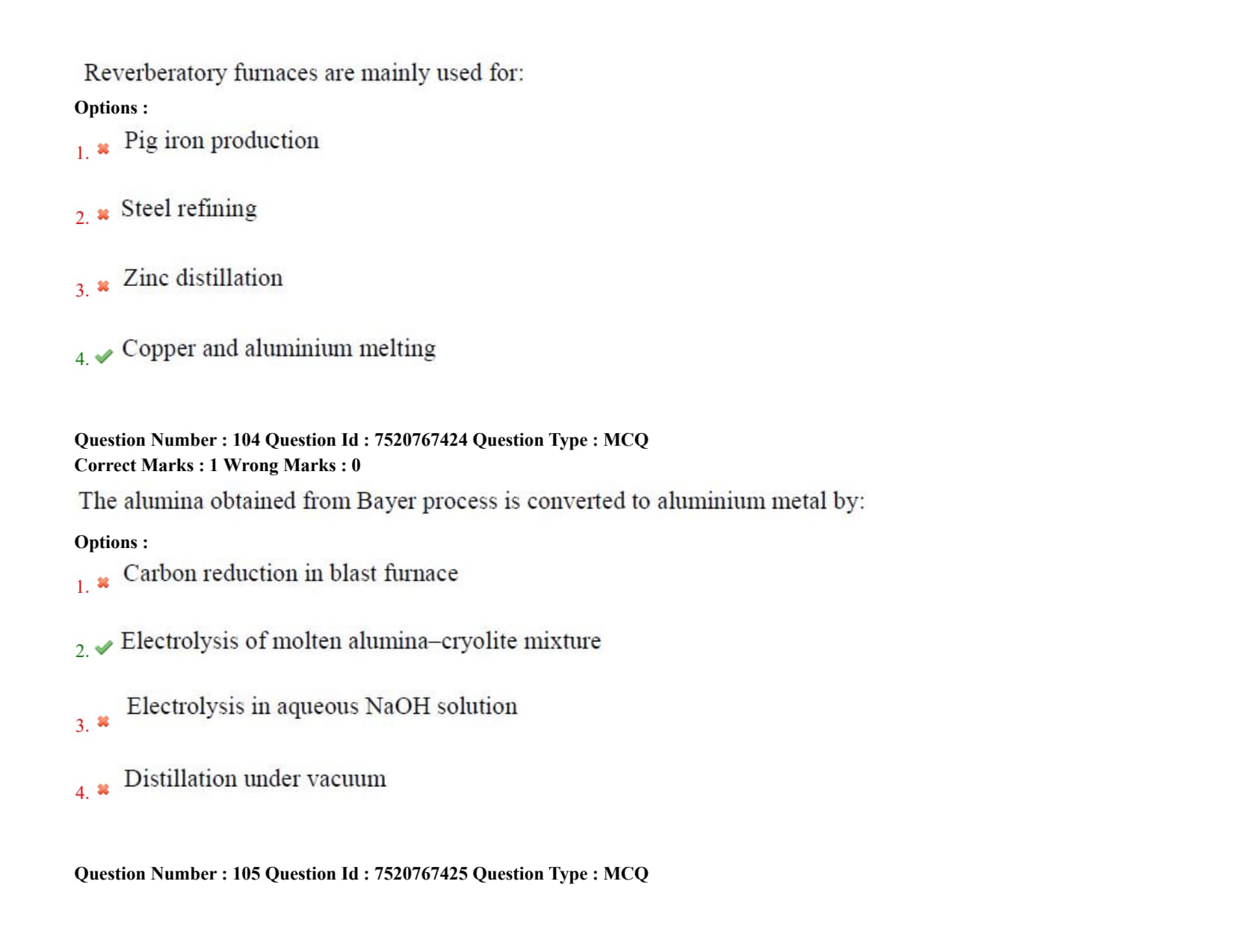
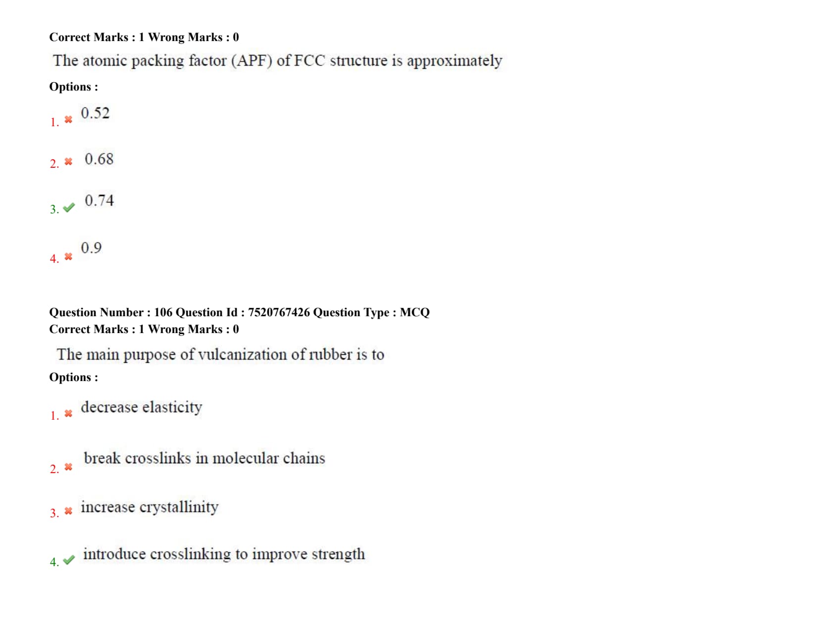
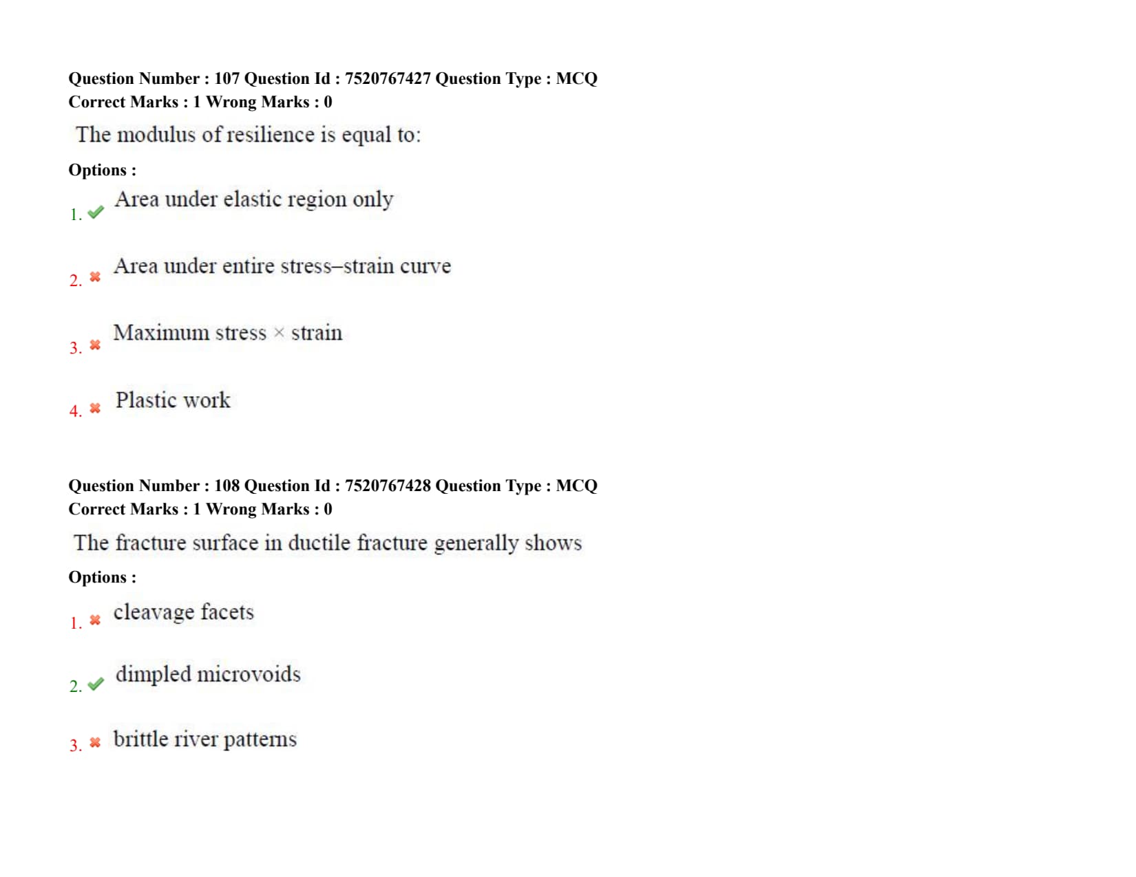
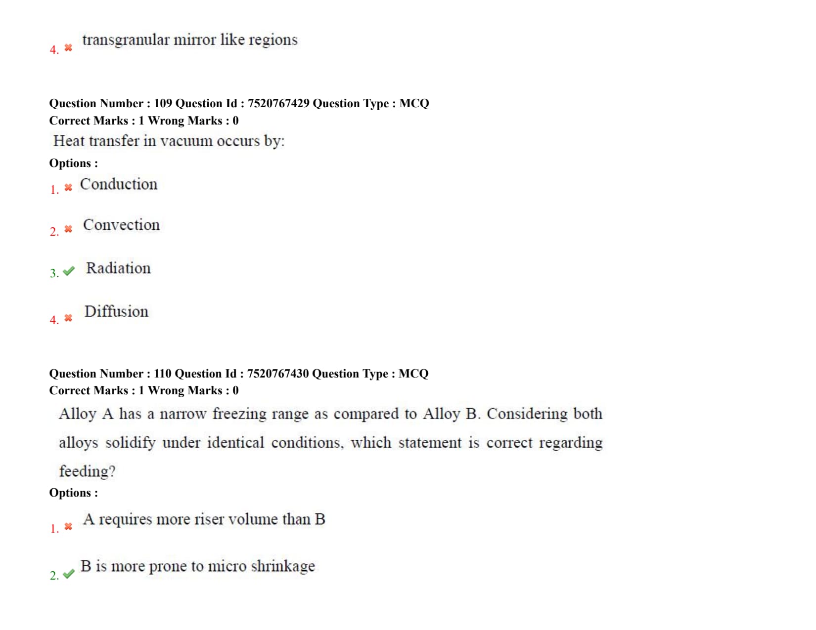
The first law of thermodynamics is based on the principle of:
Ellingham diagrams are mainly used to determine:
Detailed Solution
Step 1: Understanding the Question:
The question asks about the primary utility of an Ellingham diagram in metallurgical engineering.
Ellingham diagrams are thermodynamic plots widely used in pyrometallurgy to study the reduction of metal oxides, sulfides, and halides.
Step 2: Key Formula or Approach:
An Ellingham diagram plots the standard Gibbs free energy of formation (\( \Delta G^\circ \)) of oxides (usually normalized per mole of \( O_2 \)) as a function of absolute temperature (\( T \)):
\[ \Delta G^\circ = \Delta H^\circ - T\Delta S^\circ \]
where:
\( \Delta H^\circ \) is the standard enthalpy of formation, and
\( \Delta S^\circ \) is the standard entropy of formation.
Step 3: Detailed Explanation:
Oxide Stability Assessment: The relative position of the curves on the diagram indicates the thermodynamic stability of the respective oxides.
A lower position on the diagram (more negative \( \Delta G^\circ \)) corresponds to a more stable oxide because more energy is released during its formation.
Reducing Agent Selection: The diagram helps determine which reducing agent (such as Carbon, Carbon Monoxide, or another metal) can successfully reduce a specific metal oxide at a given temperature.
A metal whose line lies lower on the diagram can reduce the oxide of a metal whose line lies higher on the diagram.
Limitations: The Ellingham diagram is purely thermodynamic and does not provide information regarding reaction kinetics (Option C) or diffusion parameters (Option D).
It also does not directly represent multi-component phase equilibria (Option A).
Step 4: Final Answer:
Hence, the primary use of Ellingham diagrams is to determine oxide stability, which aligns with Option (B).
Quick Tip: The lower a line is on the Ellingham diagram, the more stable the oxide is, meaning it is harder to reduce but has a stronger affinity for oxygen.
The equilibrium constant of a reaction depends mainly on:
Detailed Solution
Step 1: Understanding the Question:
The question asks for the primary variable that determines the value of the thermodynamic equilibrium constant (\( K \)) of a chemical reaction.
Step 2: Key Formula or Approach:
The relationship between the standard Gibbs free energy change (\( \Delta G^\circ \)) and the equilibrium constant (\( K \)) is expressed as:
\[ \Delta G^\circ = -R T \ln K \]
Rearranging this equation gives:
\[ \ln K = -\frac{\Delta G^\circ}{R T} \]
Further, substituting \( \Delta G^\circ = \Delta H^\circ - T \Delta S^\circ \) yields:
\[ \ln K = -\frac{\Delta H^\circ}{R T} + \frac{\Delta S^\circ}{R} \]
Step 3: Detailed Explanation:
Temperature Dependence: The standard Gibbs free energy change (\( \Delta G^\circ \)) is defined for reactants and products in their standard states, which makes it independent of pressure and concentration.
Consequently, \( \Delta G^\circ \) and the equilibrium constant (\( K \)) depend exclusively on temperature.
Effect of Other Parameters:
- Pressure and Volume (Options A and C) can shift the position of equilibrium (as described by Le Chatelier's principle) but do not change the actual value of the equilibrium constant \( K \) for a gas-phase reaction behaving ideally.
- Catalysts (Option D) increase the rate of both forward and reverse reactions equally, reducing the time to reach equilibrium without altering the equilibrium composition or the value of \( K \).
Step 4: Final Answer:
Thus, the equilibrium constant of a reaction depends mainly on temperature, corresponding to Option (B).
Quick Tip: Remember the Van 't Hoff equation: the change in the equilibrium constant with temperature depends on whether the reaction is exothermic or endothermic. No other physical parameter can alter \( K \).
Diffusion governed by concentration gradient follows
Detailed Solution
Step 1: Understanding the Question:
The question asks for the fundamental law that governs mass transport (diffusion) under the influence of a concentration gradient.
Step 2: Key Formula or Approach:
For steady-state diffusion, Fick's First Law relates the diffusion flux (\( J \)) to the concentration gradient:
\[ J = -D \frac{dC}{dx} \]
where:
\( J \) is the diffusion flux,
\( D \) is the diffusion coefficient, and
\( \frac{dC}{dx} \) is the concentration gradient.
For non-steady-state diffusion, Fick's Second Law is used:
\[ \frac{\partial C}{\partial t} = D \frac{\partial^2 C}{\partial x^2} \]
Step 3: Detailed Explanation:
Fick's Laws of Diffusion: These laws mathematically describe the process of diffusion, illustrating how atoms or molecules move from regions of high concentration to regions of low concentration.
Comparison with Other Options:
- Newton's law (Option A) refers to viscosity in fluids or laws of classical mechanics.
- Hooke's law (Option C) governs the linear elastic behavior of solids, stating that stress is proportional to strain.
- Faraday's law (Option D) describes electromagnetic induction or electrochemical electrolysis.
Step 4: Final Answer:
Therefore, concentration-gradient-driven diffusion is described by Fick's law, which matches Option (B).
Quick Tip: Fick's First Law is analogous to Fourier's Law of heat conduction and Ohm's Law of electrical conduction, where flux is proportional to a driving force gradient.
Bernoulli's equation relates
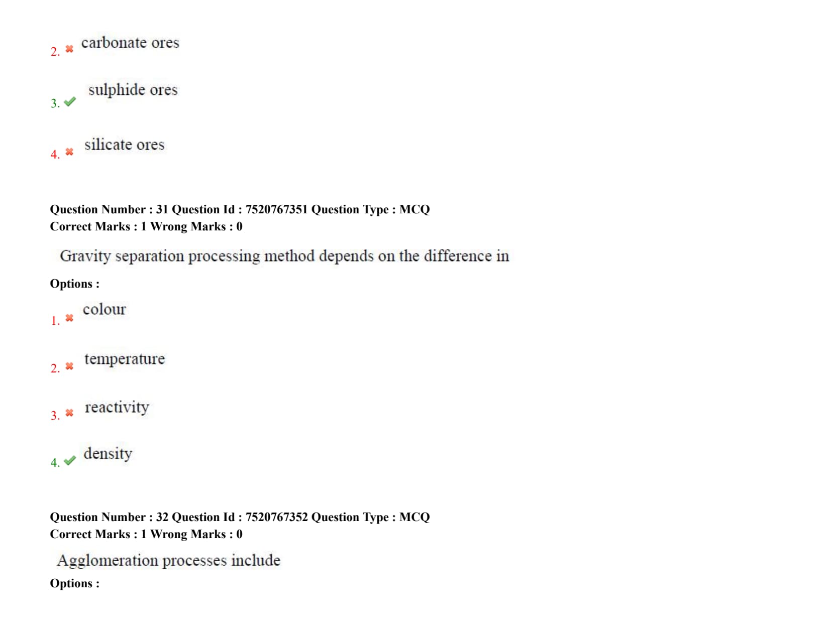
Reaction order describes dependence of rate on
Detailed Solution
Step 1: Understanding the Question:
The question asks which parameter's effect on reaction rate is described by the "order of a reaction" in chemical kinetics.
Step 2: Key Formula or Approach:
For a general chemical reaction: \[ aA + bB \rightarrow Products \]
The rate law is mathematically represented as: \[ Rate = k [A]^x [B]^y \]
where: \( k \) is the rate constant,
\( [A] \) and \( [B] \) are the molar concentrations of the reactants, and
\( x \) and \( y \) are the partial reaction orders with respect to reactants A and B.
The overall reaction order is defined as \( n = x + y \).
Step 3: Detailed Explanation:
Concentration Dependence: The reaction order defines the relationship between the rate of a chemical reaction and the concentration of its reactants.
For example, in a first-order reaction (\( n = 1 \)), doubling the concentration of the reactant doubles the rate of the reaction.
Experimental Nature: Reaction order is an experimentally determined quantity and cannot be deduced solely from the stoichiometric coefficients of the balanced chemical equation.
Role of Other Variables:
- Temperature (Option B) influences the rate constant \( k \) via the Arrhenius equation (\( k = A e^{-E_a/RT} \)), not the reaction order.
- Pressure (Option C) primarily affects gas-phase reaction rates by changing the effective concentration.
- Catalysts (Option D) lower the activation energy, changing the mechanism and rate constant, but do not define the basic concentration-dependent order.
Step 4: Final Answer:
Consequently, reaction order describes the dependence of reaction rate on concentration, matching Option (A).
Quick Tip: The order of a reaction can be zero, fractional, or an integer, whereas the molecularity of an elementary reaction must always be a positive integer.
High temperature corrosion mainly involves
Detailed Solution
Step 1: Understanding the Question:
The question asks about the primary chemical or physical process that drives high-temperature corrosion of metals.
High-temperature corrosion is a form of corrosion that occurs in the absence of a liquid aqueous electrolyte, often termed "dry corrosion" or "scaling".
Step 2: Key Formula or Approach:
The primary reaction during high-temperature oxidation of a metal \( M \) in an oxygen environment is:
\[ x M + \frac{y}{2} O_2 \rightarrow M_xO_y \]
This reaction is thermodynamically driven by the negative Gibbs free energy of formation of the metal oxide.
Step 3: Detailed Explanation:
Oxidation Mechanism: At elevated temperatures, metals directly react with gaseous species in the environment (such as oxygen, sulfur, or carbon).
The most common and widespread high-temperature corrosion process is oxidation, where a solid metal oxide scale forms on the metal surface.
Role of Diffusion: Although the growth of the oxide scale is often limited by the solid-state diffusion of metal cations or oxygen anions through the scale, the core chemical process is fundamentally an oxidation reaction.
Therefore, calling it "diffusion of gases only" (Option A) is incorrect as it neglects metal ion transport and the chemical reaction itself.
Distinction from Mechanical Processes: Mechanical wear (Option B) and plastic deformation (Option C) are physical degradation modes, not chemical corrosion phenomena, though they can interact with corrosion at high temperatures.
Step 4: Final Answer:
Hence, high-temperature corrosion mainly involves oxidation reactions, which corresponds to Option (D).
Quick Tip: The Pilling-Bedworth ratio (PBR) is used to predict whether a metal oxide scale will be protective or non-protective based on the volume ratio of oxide to metal.
The driving force for diffusion is
Detailed Solution
Step 1: Understanding the Question:
The question asks for the fundamental thermodynamic driving force that causes atomic or molecular diffusion.
Step 2: Key Formula or Approach:
Thermodynamically, the diffusion flux (\( J_i \)) of a species \( i \) is proportional to the gradient of its chemical potential (\( \mu_i \)):
\[ J_i = - L_i \frac{d\mu_i}{dx} \]
where:
\( L_i \) is a phenomenological mobility coefficient, and
\( \frac{d\mu_i}{dx} \) is the chemical potential gradient.
Step 3: Detailed Explanation:
Chemical Potential vs. Concentration Gradient: While Fick's first law defines diffusion in terms of a concentration gradient (\( \frac{dC}{dx} \)), this is an approximation valid only for ideal solutions.
In non-ideal solutions, species can sometimes diffuse from low-concentration regions to high-concentration regions (known as uphill diffusion), which happens during spinodal decomposition or phase separation.
Thermodynamic Driving Force: The true driving force is always the minimization of the Gibbs free energy, which is represented by the gradient of chemical potential. Atoms migrate to equalize chemical potentials.
Analysis of Other Options:
- Temperature gradients (Option A) can cause thermal diffusion (Soret effect), but they are not the primary driving force for ordinary mass diffusion.
- Pressure gradients (Option B) can drive fluid bulk flow (advection) or pressure-induced diffusion, but not standard atomic diffusion in materials.
- Magnetic fields (Option D) affect magnetic domains but do not drive mass diffusion.
Step 4: Final Answer:
Therefore, the ultimate driving force for diffusion is the chemical potential gradient, matching Option (C).
Quick Tip: Remember that "uphill diffusion" shows that concentration gradient is not the ultimate driving force; atoms can move up a concentration gradient to go down a chemical potential gradient.
Aqueous corrosion of metals generally involves
Detailed Solution
Step 1: Understanding the Question:
The question asks about the fundamental chemical mechanism underlying the aqueous (wet) corrosion of metals.
Step 2: Key Formula or Approach:
Aqueous corrosion requires the operation of an electrochemical cell, consisting of:
1. Anodic reaction (oxidation):
\[ M \rightarrow M^{n+} + n e^- \]
2. Cathodic reaction (reduction):
\[ 2H^+ + 2e^- \rightarrow H_2 \quad (in acidic solutions) \]
or
\[ O_2 + 2H_2O + 4e^- \rightarrow 4OH^- \quad (in neutral or basic solutions) \]
Step 3: Detailed Explanation:
Electrochemical Mechanism: Aqueous corrosion is fundamentally an electrochemical process involving the transfer of electrons.
It requires four vital components: an anode (where the metal dissolves), a cathode (where a reduction reaction occurs), an electrical path through the metal, and an ionic path through the electrolyte (water containing dissolved salts/gases).
Comparison with Other Options:
- Mechanical wear (Option B) is physical degradation. Though it can synergize with corrosion (erosion-corrosion), it is not the mechanism of chemical attack.
- Thermal decomposition (Option C) involves breakdown of compounds due to heat, which is unrelated to liquid-phase wet corrosion.
- Magnetic interaction (Option D) has no direct role in standard metal corrosion pathways.
Step 4: Final Answer:
Thus, aqueous corrosion of metals involves electrochemical reactions, which corresponds to Option (A).
Quick Tip: For aqueous corrosion to occur, all four elements of the electrochemical cell (anode, cathode, electrolyte, and metallic path) must be present. Removing any one stops the corrosion.
Radiation heat transfer occurs through
Diffusion in solids is faster when
Detailed Solution
Step 1: Understanding the Question:
The question asks which physical parameter changes in a way that accelerates the rate of solid-state atomic diffusion.
Step 2: Key Formula or Approach:
The temperature dependence of the diffusion coefficient (\( D \)) is mathematically expressed by the Arrhenius equation:
\[ D = D_0 \exp\left(-\frac{Q}{RT}\right) \]
where:
\( D_0 \) is the pre-exponential factor,
\( Q \) is the activation energy for diffusion,
\( R \) is the universal gas constant, and
\( T \) is the absolute temperature.
Step 3: Detailed Explanation:
Temperature Effect: An increase in temperature exponentially increases the value of the diffusion coefficient \( D \).
Higher thermal energy increases atomic vibration amplitudes, providing more atoms with the kinetic energy necessary to overcome the activation barrier \( Q \) and jump to adjacent vacancy or interstitial sites.
Analysis of Other Options:
- Grain size increases (Option B) actually reduces the total boundary area. Since diffusion along grain boundaries is faster than bulk lattice diffusion, larger grains lead to slower overall diffusion.
- Density increases (Option D) generally means tighter atomic packing, which increases the activation energy barrier for atomic jumps, slowing down diffusion.
- Pressure decreases (Option A) has a minor effect on solid-state diffusion compared to temperature.
Step 4: Final Answer:
Thus, diffusion in solids is faster when temperature increases, aligning with Option (C).
Quick Tip: Solid-state diffusion is a thermally activated process. As temperature increases, the concentration of vacancies increases, providing more pathways for atomic movement.
Diffusion in metals generally increases with
Detailed Solution
Step 1: Understanding the Question:
The question asks about the relationship between solid-state diffusion in metals and different environmental/material parameters.
Step 2: Key Formula or Approach:
Diffusion in metals is governed by the diffusivity or diffusion coefficient \( D \), which is related to absolute temperature through the Arrhenius relation:
\[ D = D_0 e^{-\frac{Q}{RT}} \]
This relationship indicates that diffusion is highly sensitive to thermal activation.
Step 3: Detailed Explanation:
Direct Influence of Temperature: As temperature rises, atoms gain more kinetic energy, which drastically increases the frequency of atomic jumps into adjacent lattice vacancies or interstitial sites.
Thus, the rate of atomic movement (diffusion) increases with increasing temperature.
Analysis of Other Options:
- Decreasing temperature (Option A) reduces thermal vibrations, lowering the atomic jump rate and decreasing diffusion.
- Increasing pressure (Option B) typically decreases the vacancy concentration and increases the activation volume, which hinders diffusion.
- Increasing density (Option C) reduces free volume and makes atomic motion more difficult, slowing down diffusion.
Step 4: Final Answer:
Therefore, diffusion in metals generally increases with increasing temperature, which is Option (D).
Quick Tip: Always relate diffusion rates directly to the exponential temperature term \( e^{-Q/RT} \). Even a small increase in temperature can lead to a massive increase in diffusion rates.
Which type of corrosion protection involves connecting the metal to be protected to a more reactive "sacrificial" metal?
Detailed Solution
Step 1: Understanding the Question:
The question asks for the name of the corrosion prevention technique where a target metal is connected to a more reactive (less noble) metal that corrodes preferentially to protect the target.
Step 2: Key Formula or Approach:
The galvanic series dictates which metal will act as an anode when coupled.
The sacrificial metal (more active, e.g., Zinc or Magnesium) oxidizes:
\[ M_{sacrificial} \rightarrow M_{sacrificial}^{n+} + n e^- \]
The electrons flow to the protected metal (e.g., Iron), making it cathodic and protecting it:
\[ O_2 + 2H_2O + 4e^- \rightarrow 4OH^- \]
Step 3: Detailed Explanation:
Cathodic Protection (Sacrificial Anode): In this method, the protected metal is made the cathode of an electrochemical cell.
By connecting it electrically to a more active, sacrificial anode (like Zinc or Magnesium), the sacrificial anode undergoes oxidation (corrosion) instead of the protected structural metal.
Comparison with Other Options:
- Anodic protection (Option A) involves applying an external anodic current to shift the metal potential into its passive region.
- Passivation (Option C) refers to the spontaneous formation of a protective oxide film (like on stainless steel) without external electrical connection.
- Galvanizing (Option D) is a specific method of applying a zinc coating on steel. While it utilizes cathodic protection principles, the overall engineering practice of using connected blocks of reactive metals is termed Cathodic Protection.
Step 4: Final Answer:
Thus, the correct answer is Cathodic protection, which corresponds to Option (B).
Quick Tip: Zinc, Magnesium, and Aluminum are commonly used as sacrificial anodes because they lie lower (more active/reactive) in the galvanic series compared to steel.
The Pourbaix diagram represents the metal's:
Detailed Solution
Step 1: Understanding the Question:
The question asks what physical or electrochemical variables are mapped on a Pourbaix diagram.
Step 2: Key Formula or Approach:
Pourbaix diagrams are calculated based on the Nernst equation for electrochemical reactions:
\[ E = E^\circ - \frac{RT}{nF} \ln Q \]
For reactions involving hydrogen ions (\( H^+ \)), the potential \( E \) becomes a linear function of pH, since:
\[ pH = -\log[H^+] \]
Step 3: Detailed Explanation:
Variables Mapped: A Pourbaix diagram is a thermodynamic plot of electrode potential (\( E \), usually relative to the Standard Hydrogen Electrode on the y-axis) versus \( pH \) (on the x-axis) for a metal-water system.
Stability Regions: The diagram is divided into major thermodynamic regions:
1. Immunity: The metal itself is thermodynamically stable and will not corrode.
2. Corrosion: Soluble metal ions are stable, meaning the metal will actively dissolve.
3. Passivity: Insoluble oxides or hydroxides form a protective surface film, limiting further corrosion.
Other Options: The diagram does not contain any mechanical (Option A), electrical (Option C), or magnetic (Option D) properties.
Step 4: Final Answer:
Therefore, the Pourbaix diagram represents the Potential-pH stability regions of a metal, corresponding to Option (B).
Quick Tip: Horizontal lines on a Pourbaix diagram represent pure electron-transfer reactions (independent of pH), while vertical lines represent pure acid-base reactions (independent of potential).
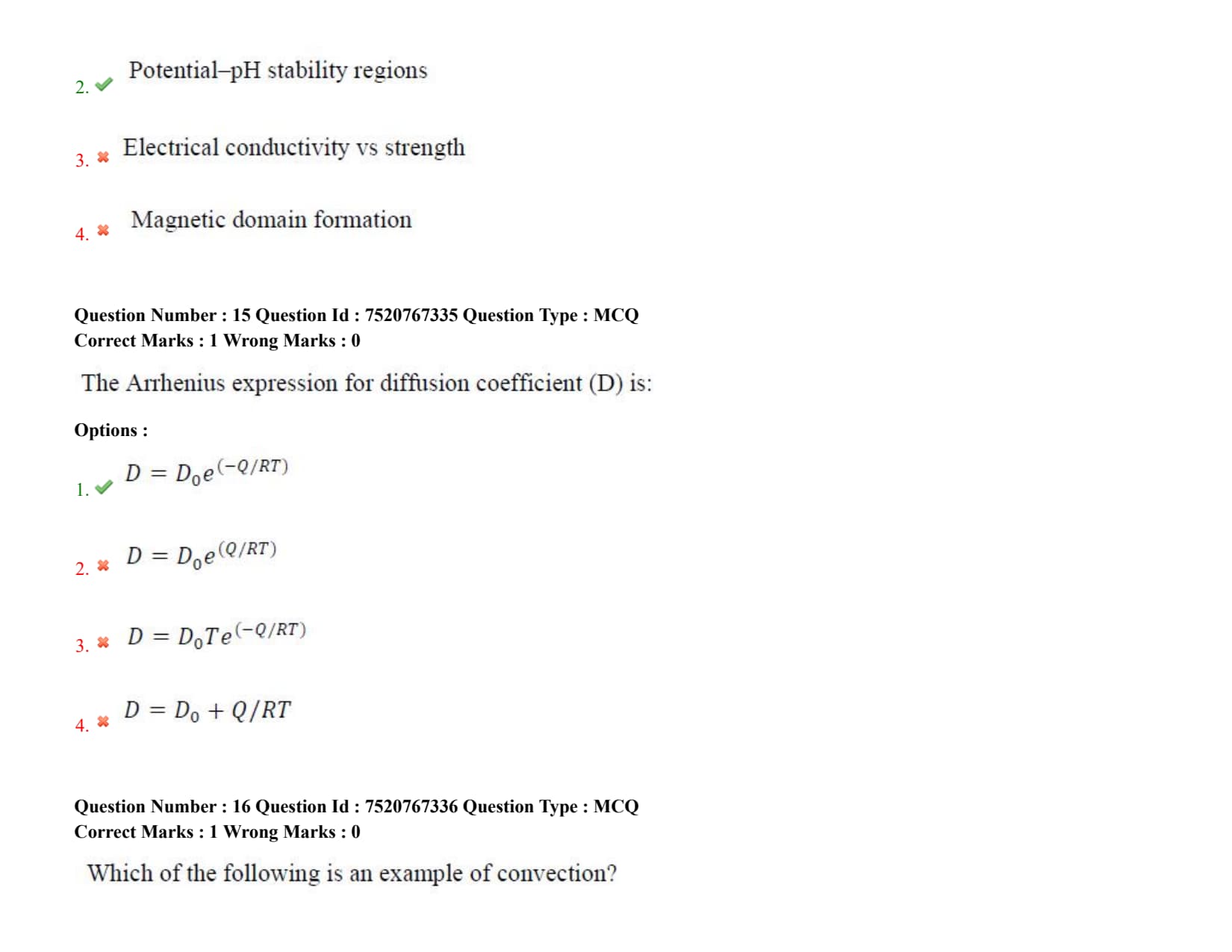
The Arrhenius expression for diffusion coefficient (D) is:
Detailed Solution
Step 1: Understanding the Question:
The question asks for the standard Arrhenius mathematical expression that models how the solid-state diffusion coefficient \( D \) varies with absolute temperature \( T \).
Step 2: Key Formula or Approach:
The diffusion of atoms requires them to jump over potential energy barriers. The rate of these jumps is thermally activated, following the Arrhenius rate equation.
Step 3: Detailed Explanation:
Equation Parameters: The standard equation is:
\[ D = D_0 e^{-\frac{Q}{RT}} \]
where:
\( D \) is the diffusion coefficient (or diffusivity) in \( m^2/s \),
\( D_0 \) is the temperature-independent pre-exponential factor,
\( Q \) is the activation energy for diffusion (in \( J/mol \) or \( eV/atom \)),
\( R \) is the gas constant, and
\( T \) is the absolute temperature in Kelvin.
Physical Meaning: The exponential term \( e^{-Q/RT} \) represents the fraction of atom vibrations that possess energy equal to or greater than the activation energy barrier \( Q \).
Plotting: Taking the natural logarithm of both sides yields:
\[ \ln D = \ln D_0 - \frac{Q}{R}\left(\frac{1}{T}\right) \]
A plot of \( \ln D \) vs \( 1/T \) yields a straight line with a slope of \( -Q/R \).
Step 4: Final Answer:
Thus, the correct Arrhenius expression is \( D = D_0 e^{(-Q/RT)} \), which matches Option (A).
Quick Tip: An Arrhenius-type relationship is common for many thermally activated processes in metallurgy, including vacancy formation, recrystallization, and chemical reactions.
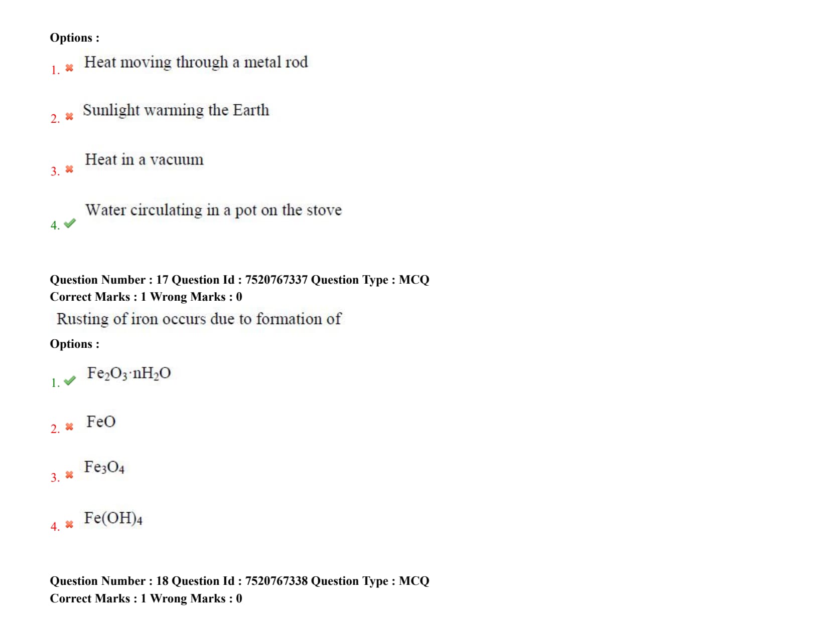
Which of the following is an example of convection?
Rusting of iron occurs due to formation of
Detailed Solution
Step 1: Understanding the Question:
The question asks for the chemical formula of the primary compound formed during the rusting of iron under atmospheric conditions.
Step 2: Key Formula or Approach:
Rusting is an electrochemical process where iron reacts with oxygen and water:
Anode: \( Fe \rightarrow Fe^{2+} + 2e^- \)
Cathode: \( O_2 + 2H_2O + 4e^- \rightarrow 4OH^- \)
The resulting iron(II) hydroxide is further oxidized by dissolved oxygen to produce hydrated iron(III) oxide:
\[ 4Fe(OH)_2 + O_2 \rightarrow 2(Fe_2O_3 \cdot nH_2O) + 2H_2O \]
Step 3: Detailed Explanation:
Hydrated Oxide Formation: Rust is chemically described as hydrated iron(III) oxide, formulated as \( Fe_2O_3 \cdot nH_2O \), where \( n \) represents varying amounts of water of hydration.
It is a reddish-brown, porous compound that does not form a protective barrier, allowing corrosion to continue into the underlying metal.
Analysis of Other Options:
- Wüstite (\( FeO \), Option B) and Magnetite (\( Fe_3O_4 \), Option C) are dry, high-temperature oxide scales that form in the absence of liquid water.
- \( Fe(OH)_4 \) (Option D) is not a stable rust constituent.
Step 4: Final Answer:
Hence, rusting of iron occurs due to the formation of hydrated iron(III) oxide (\( Fe_2O_3 \cdot nH_2O \)), corresponding to Option (A).
Quick Tip: Unlike copper or aluminum oxide scales, iron rust is highly porous and flaky, offering no protection to the underlying steel substrate.
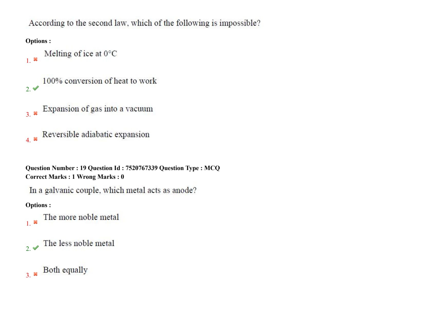
According to the second law, which of the following is impossible?
In a galvanic couple, which metal acts as anode?
Detailed Solution
Step 1: Understanding the Question:
The question asks which component metal in a galvanic couple undergoes oxidation (acts as the anode).
Step 2: Key Formula or Approach:
In electrochemistry, the tendency of a metal to lose electrons is determined by its position in the electrochemical or galvanic series.
The metal with the more negative (active/less noble) standard reduction potential will undergo oxidation:
\[ M_{active} \rightarrow M_{active}^{n+} + n e^- \]
This electrode is defined as the anode.
Step 3: Detailed Explanation:
Anodic Dissolution: When two dissimilar metals are in physical or electrical contact in the presence of an electrolyte, a galvanic couple is created.
The less noble (more active) metal has a stronger thermodynamic tendency to corrode. It acts as the anode, releasing electrons and dissolving into the electrolyte.
Cathodic Protection of the Noble Metal: The released electrons flow through the metallic connection to the more noble (less active) metal.
The more noble metal acts as the cathode, where reduction reactions occur. It is protected from corrosion at the expense of the anode.
Analysis of Other Options:
- The more noble metal (Option A) always acts as the cathode.
- They cannot act as anodes equally (Option C), and it does not depend on an applied current (Option D) since the process is spontaneously driven by the potential difference.
Step 4: Final Answer:
Therefore, the less noble metal acts as the anode in a galvanic couple, which is Option (B).
Quick Tip: In any galvanic couple, the metal that is lower (more active) in the galvanic series corrodes, while the metal that is higher (more noble) remains protected.
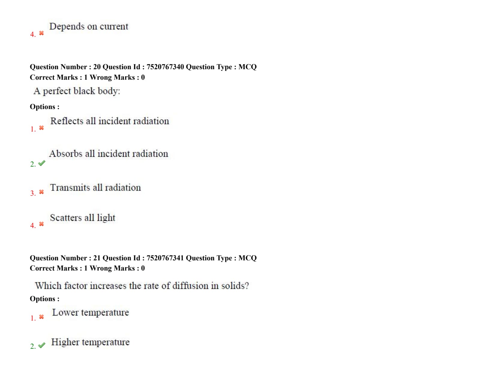
A perfect black body:
Which factor increases the rate of diffusion in solids?
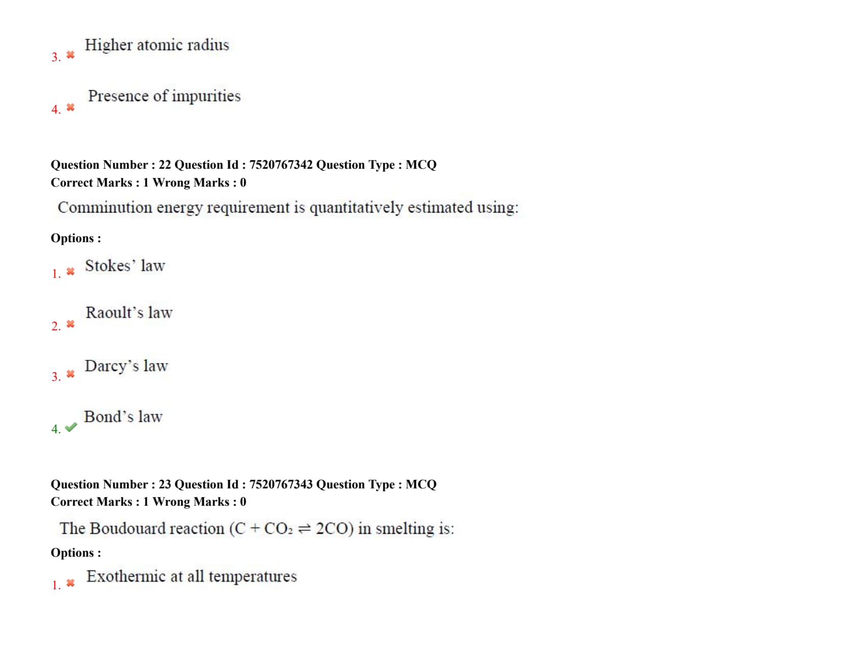
Comminution energy requirement is quantitatively estimated using:
Detailed Solution
Step 1: Understanding the Question:
The question asks for the empirical law used to quantitatively estimate the energy required for comminution processes.
Comminution is the mechanical process of reducing the particle size of ores through crushing and grinding, which is the first step in mineral processing.
Step 2: Key Formula or Approach:
The general differential equation for comminution energy states:
\[ dE = -C \frac{dX}{X^f} \]
where \( E \) is energy, \( X \) is particle size, and \( C \) and \( f \) are constants.
For Bond's Law, the value of the exponent \( f \) is chosen as \( 1.5 \). Integration yields:
\[ E = 10 \cdot W_i \left( \frac{1}{\sqrt{P_{80}}} - \frac{1}{\sqrt{F_{80}}} \right) \]
where:
\( E \) is the specific energy input (\( kWh/ton \)),
\( W_i \) is the Bond Work Index of the material,
\( F_{80} \) is the feed size at which \( 80% \) of particles pass, and
\( P_{80} \) is the product size at which \( 80% \) of particles pass.
Step 3: Detailed Explanation:
Bond's Third Theory of Comminution: Bond's law states that the work useful in cracking is directly proportional to the length of new cracks formed.
Since crack length is proportional to the square root of the new surface area created, the energy required is inversely proportional to the square root of the product particle size.
It is widely used in the mining industry for sizing industrial crushers and tumbling mills.
Comparison with Other Options:
- Stokes' law (Option A) determines the settling velocity of spherical particles in a viscous fluid, which is relevant to classification but not size reduction energy.
- Raoult's law (Option B) describes the vapor pressure of ideal thermodynamic solutions.
- Darcy's law (Option C) describes the flow of fluid through a porous medium.
Step 4: Final Answer:
Thus, the comminution energy requirement is quantitatively estimated using Bond's law, which is Option (D).
Quick Tip: Remember the three classical comminution theories: von Rittinger's (energy proportional to new surface area), Kick's (energy proportional to volume reduction ratio), and Bond's (energy proportional to crack length, suitable for intermediate grinding sizes).
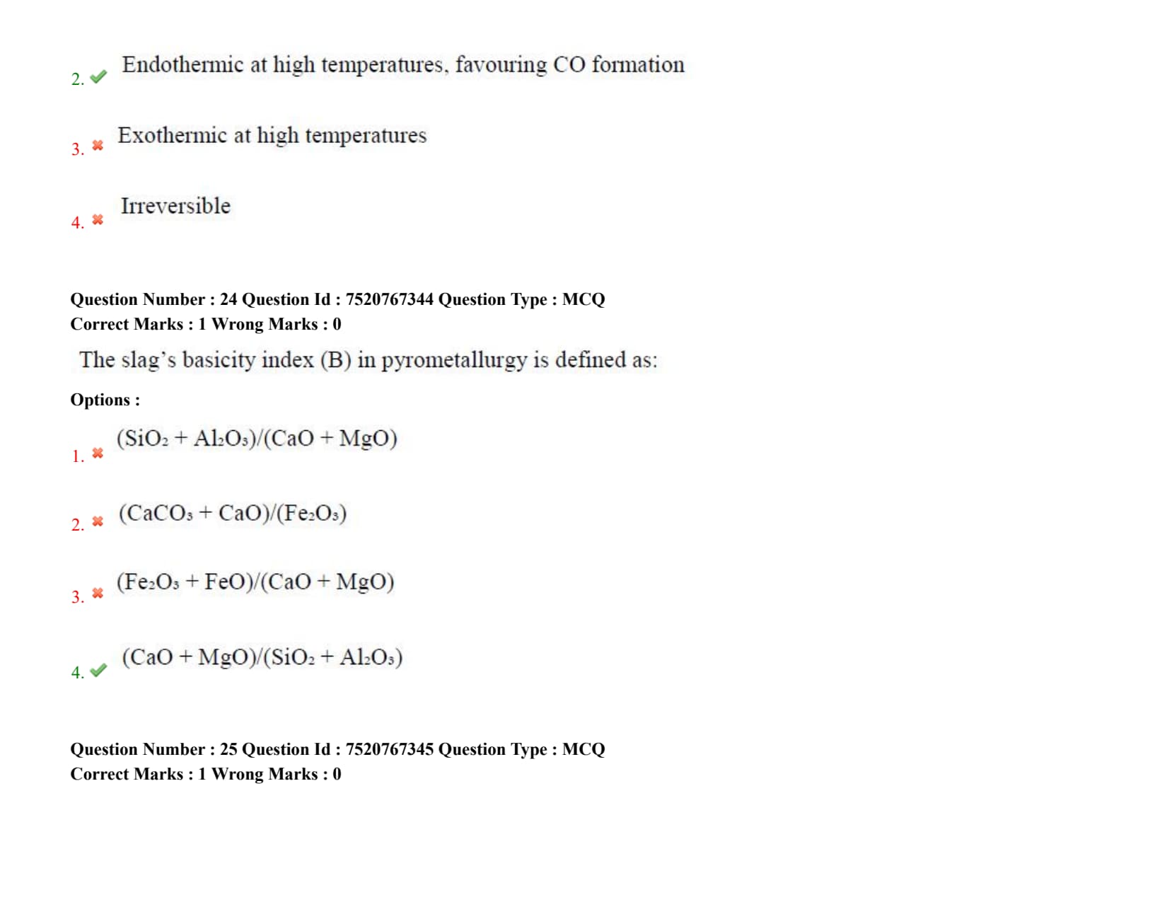
The Boudouard reaction (\( C + CO_2 \rightleftharpoons 2CO \)) in smelting is:
Detailed Solution
Step 1: Understanding the Question:
The question asks about the thermodynamic nature and temperature dependence of the Boudouard reaction inside an extraction reactor (like an iron blast furnace).
The Boudouard reaction represents the chemical equilibrium between solid carbon (coke) and carbon oxides (carbon dioxide and carbon monoxide).
Step 2: Key Formula or Approach:
The Boudouard reaction is written as:
\[ C(s) + CO_2(g) \rightleftharpoons 2CO(g) \]
At standard state, the reaction has a highly positive standard enthalpy of reaction:
\[ \Delta H^\circ \approx +172 kJ/mol \]
This positive value of enthalpy indicates that the reaction is highly endothermic.
Step 3: Detailed Explanation:
Thermodynamic Analysis: Because the standard enthalpy of reaction \( \Delta H^\circ \) is positive, Le Chatelier's principle dictates that an increase in temperature will shift the chemical equilibrium in the forward direction.
Thus, higher temperatures favor the forward, endothermic reaction, leading to a higher concentration of carbon monoxide (\( CO \)) gas relative to carbon dioxide (\( CO_2 \)).
Entropy Effect: The reaction involves the conversion of one mole of gas into two moles of gas, resulting in a positive entropy change (\( \Delta S^\circ > 0 \)).
Since \( \Delta G^\circ = \Delta H^\circ - T\Delta S^\circ \), a positive \( \Delta S^\circ \) causes the term \( -T\Delta S^\circ \) to become increasingly negative at higher temperatures, eventually overcoming the positive \( \Delta H^\circ \) and making \( \Delta G^\circ \) spontaneous (\( \Delta G^\circ < 0 \)) at high temperatures.
Smelting Importance: In the blast furnace, this reaction is crucial because it regenerates the reducing gas (\( CO \)) required for reducing iron oxides.
However, due to its endothermic nature, it consumes a large amount of thermal energy in the lower zones of the furnace.
Step 4: Final Answer:
Therefore, the Boudouard reaction is endothermic at high temperatures, favoring CO formation, which corresponds to Option (B).
Quick Tip: At temperatures below \( 700^\circC \), the equilibrium strongly favors \( CO_2 \) and carbon, whereas above \( 1000^\circC \), the gas phase consists of more than \( 99% CO \).
The slag's basicity index (B) in pyrometallurgy is defined as:
Detailed Solution
Step 1: Understanding the Question:
The question asks for the definition of the basicity index of metallurgical slag.
Slag is a liquid mixture of various oxides that forms during pyrometallurgical smelting and refining to collect impurities and protect the molten metal.
Step 2: Key Formula or Approach:
Oxides in slag are broadly classified into basic oxides (which donate oxygen ions, e.g., \( CaO \), \( MgO \)) and acidic oxides (which accept oxygen ions to form complex network structures, e.g., \( SiO_2 \), \( Al_2O_3 \)).
The basicity index (\( B \)) is generally defined as the mass ratio of basic oxides to acidic oxides in the slag:
\[ B = \frac{% Basic Oxides}{% Acidic Oxides} \]
Step 3: Detailed Explanation:
Quantification of Basicity: The most common and widely used expression for multi-component slag basicity is the quaternary basicity index:
\[ B = \frac{wt% CaO + wt% MgO}{wt% SiO_2 + wt% Al_2O_3} \]
Here, \( CaO \) and \( MgO \) act as network modifiers (bases) that break down the complex silicate polymer chains.
\( SiO_2 \) acts as a major network former (acid), and \( Al_2O_3 \) behaves amphoterically but is grouped with acids in this basicity index formulation.
Process Control Importance: Basicity control is vital because it determines slag viscosity, melting point, and its capacity to dissolve harmful impurities like sulfur and phosphorus during steelmaking.
A highly basic slag has high desulfurization capability but must be carefully managed to avoid excessively high melting points.
Step 4: Final Answer:
Therefore, the slag's basicity index is defined by the ratio in Option (D).
Quick Tip: Basic slags with \( B > 1 \) are required in basic oxygen steelmaking (BOS) for effective phosphorus and sulfur removal. In contrast, blast furnace slags typically operate with \( B \approx 1.1 to 1.3 \).
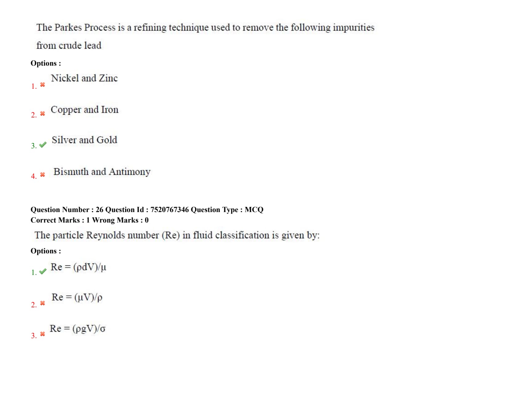
The Parkes Process is a refining technique used to remove the following impurities from crude lead
Detailed Solution
Step 1: Understanding the Question:
The question asks to identify the specific impurity elements removed from crude lead using the Parkes process during pyrometallurgical refining.
Step 2: Key Formula or Approach:
The process relies on the principle of liquid-liquid extraction.
It utilizes the selective solubility and partition coefficient of precious metals (silver and gold) between liquid zinc and liquid lead, along with the differences in their melting temperatures.
Step 3: Detailed Explanation:
Operational Principle: Zinc is added to molten lead at temperatures around \( 450^\circC to 480^\circC \).
Silver and gold are much more soluble in liquid zinc than in liquid lead.
Furthermore, zinc and lead are nearly immiscible in this temperature range, forming two distinct liquid layers with the zinc-rich layer floating on top.
Precipitation and Skimming: On cooling the mixture slightly, a solid crust containing intermetallic compounds of zinc and precious metals (\( Ag_2Zn_3 \) and \( Au_2Zn_3 \)) forms. This crust has a lower density and higher melting point than the lead bath, causing it to float to the surface where it is skimmed off.
Precious Metal Recovery: The skimmed zinc crust is then processed via retorting (distillation) to vaporize and recover the zinc, leaving behind a concentrated alloy of silver and gold (dore metal), which is further refined by cupellation.
Step 4: Final Answer:
Thus, the Parkes Process is used to remove silver and gold from crude lead, matching Option (C).
Quick Tip: The Parkes process is an excellent industrial application of partition law, where precious metals act as solutes distributing themselves preferentially into the solvent zinc.
The particle Reynolds number (Re) in fluid classification is given by:
Which refining method is most suitable for zinc?
Detailed Solution
Step 1: Understanding the Question:
The question asks for the most suitable refining process used to produce high-purity zinc metal from crude zinc.
Step 2: Key Formula or Approach:
The refining technique depends on the differences in physical properties—specifically the boiling point and vapor pressure—between zinc and its common impurity elements (like Lead, Cadmium, and Iron).
Step 3: Detailed Explanation:
High Volatility of Zinc: Zinc has a exceptionally low boiling point of \( 907^\circC \) compared to other common metals.
This high volatility makes distillation processes highly efficient for its purification.
Vacuum Distillation Process: In vacuum distillation (or fractional distillation using the New Jersey column system), crude zinc is heated under reduced pressure.
Because vapor pressure is higher under vacuum, boiling and vaporization occur at lower temperatures, which saves energy and prevents oxidation.
Zinc is selectively vaporized and condensed as high-purity metal, while less volatile impurities like iron and lead remain in the liquid residue. Volatile impurities like cadmium can be separated in a subsequent distillation column.
Comparison with Other Options:
- Electro refining (Option B) is highly suitable for copper but is less economical for zinc than distillation.
- Fire refining (Option C) is used for copper and lead but cannot yield the ultra-high purity levels of zinc achieved by distillation.
- Zone refining (Option D) is reserved for semiconductors and silicon where extreme purity is needed at a very small scale, making it economically unfeasible for commodity metals like zinc.
Step 4: Final Answer:
Hence, vacuum distillation is the most suitable refining method for zinc, corresponding to Option (A).
Quick Tip: The large difference in boiling points between Zinc (\( 907^\circC \)), Cadmium (\( 767^\circC \)), and Lead (\( 1749^\circC \)) makes fractional distillation a highly logical and thermodynamic choice for refining crude zinc.
The main combustible component in most common fuels (solid, liquid and gas) is
Detailed Solution
Step 1: Understanding the Question:
The question asks for the primary element(s) that undergo combustion reactions to release thermal energy in typical fuels.
Step 2: Key Formula or Approach:
Combustion is a rapid exothermic oxidation chemical reaction.
The fundamental combustion chemical equations for fuel components are:
\[ C + O_2 \rightarrow CO_2 \quad (\Delta H^\circ = -393.5 kJ/mol) \]
\[ 2H_2 + O_2 \rightarrow 2H_2O \quad (\Delta H^\circ = -241.8 kJ/mol per mole of gas) \]
Step 3: Detailed Explanation:
Hydrocarbon Nature of Fuels: Most natural and synthetic fuels (such as coal, coke, petroleum, natural gas, gasoline, and diesel) are composed primarily of hydrocarbons or elemental carbon.
The oxidation of carbon and hydrogen atoms present in these fuels releases large amounts of energy due to the formation of highly stable chemical bonds in carbon dioxide (\( CO_2 \)) and water vapor (\( H_2O \)).
Role of Other Elements:
- Oxygen (Option A) is the oxidant required to support combustion, but it is not the combustible fuel component itself.
- Nitrogen (Option B) and Argon (Option C) are chemically inert in typical combustion processes. They do not combust and instead act as thermal diluents in combustion air, carrying away some sensible heat.
Step 4: Final Answer:
Thus, the main combustible components in common fuels are carbon and hydrogen, matching Option (D).
Quick Tip: The ratio of hydrogen to carbon in a fuel determines its calorific value and carbon footprint, with hydrogen-rich fuels releasing more energy per unit mass and producing less \( CO_2 \).
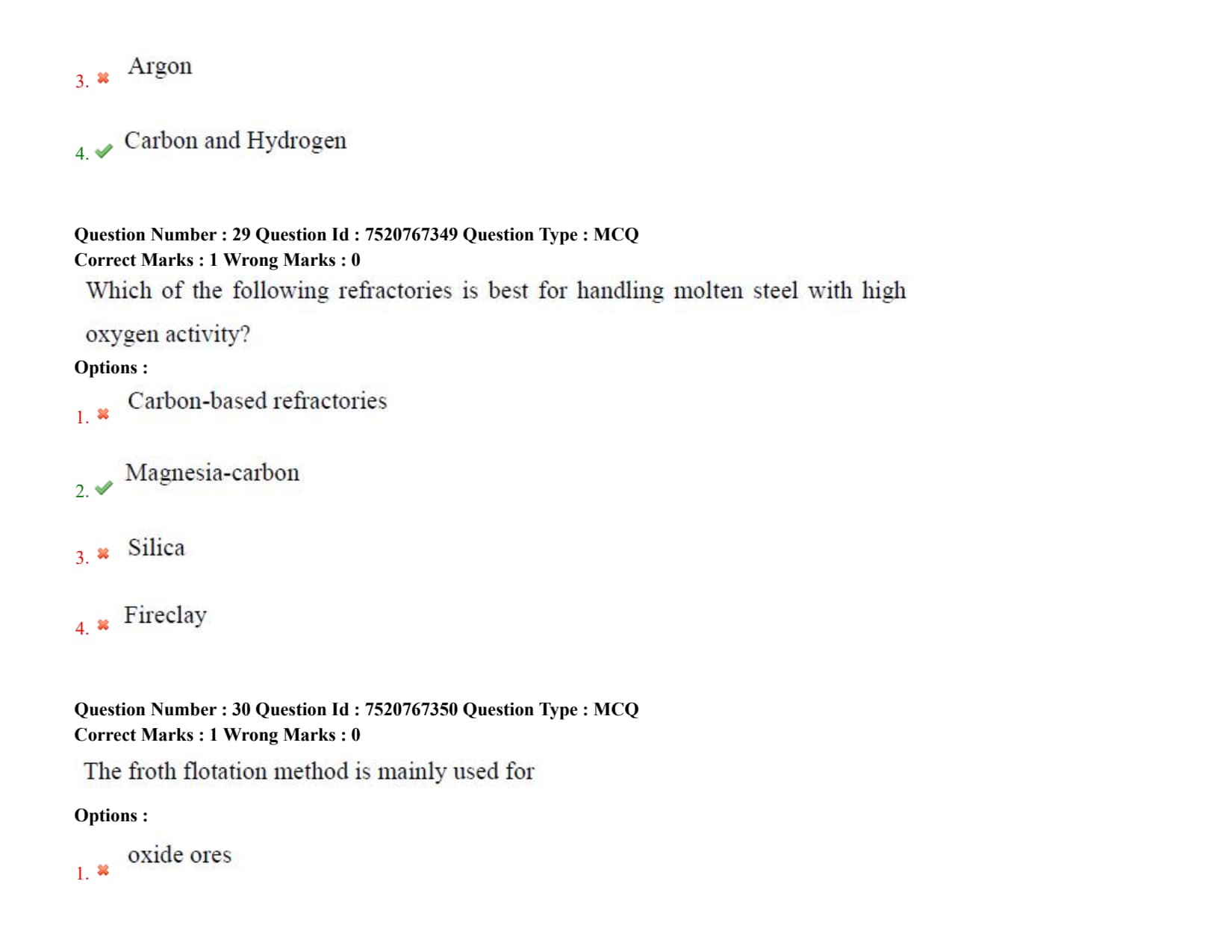
Which of the following refractories is best for handling molten steel with high oxygen activity?
The froth flotation method is mainly used for
Gravity separation processing method depends on the difference in
Detailed Solution
Step 1: Understanding the Question:
The question asks for the primary physical property difference exploited in gravity concentration (separation) techniques during mineral processing.
Step 2: Key Formula or Approach:
The efficiency of separation by gravity methods can be estimated using the Concentration Criterion (\( CC \)):
\[ CC = \frac{\rho_h - \rho_f}{\rho_l - \rho_f} \]
where:
\( \rho_h \) is the density of the heavy mineral,
\( \rho_l \) is the density of the light mineral, and
\( \rho_f \) is the density of the fluid medium (usually water or air).
A concentration criterion value greater than \( 2.5 \) indicates that gravity separation is highly efficient.
Step 3: Detailed Explanation:
Operating Principle: Gravity separation methods separate minerals based on the differences in their specific gravity (density) and their movement in a fluid medium under the action of gravitational or centrifugal forces.
- Heavy minerals (such as gold, hematite, or galena) experience a larger downward gravitational force and settle more rapidly.
- Light minerals (such as quartz or silicate gangue) settle slowly and are carried away by the fluid current.
Common Equipment: This principle is utilized in various mineral processing units, including jigs, shaking tables, spirals, and dense medium separators (DMS).
Incorrect Options:
- Colour (Option A) is used in sensor-based optical sorting.
- Temperature (Option B) is not a static material property used for separation.
- Chemical reactivity (Option C) is exploited in leaching and chemical separation, not gravity concentration.
Step 4: Final Answer:
Hence, the gravity separation method depends on the difference in density, which corresponds to Option (D).
Quick Tip: Gravity separation is highly economical and environmentally friendly because it uses water as the primary separating medium and avoids the use of toxic chemical reagents.
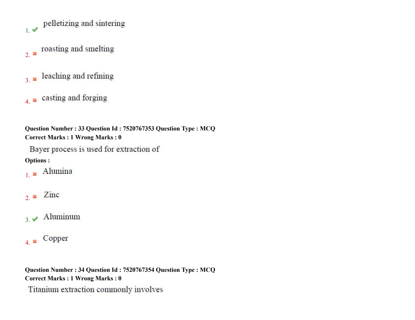
Agglomeration processes include
Detailed Solution
Step 1: Understanding the Question:
The question asks to identify the industrial operations categorized under "agglomeration" processes in extractive metallurgy.
Agglomeration is a process of sizing ultra-fine mineral particles into larger, cohesive lumps of controlled size and strength suitable for subsequent furnace operations.
Step 2: Key Formula or Approach:
Agglomeration is necessary because charging fine ores directly into a blast furnace blocks the flow of rising reducing gases, causing pressure drops and operational instability.
Step 3: Detailed Explanation:
Sintering: Sintering involves heating a mixture of fine iron ore, flux, and coke breeze to a temperature just below the melting point of the metal oxides.
This causes partial melting, creating liquid bridges that bind the fine particles into a porous, strong clinker (sinter) upon cooling.
Pelletizing: Pelletizing is a two-step process. First, very fine ore concentrates are rolled in a drum with a binder (like bentonite clay) to form green, spherical pellets.
These pellets are then fired at high temperatures (\( 1200^\circC to 1300^\circC \)) in a kiln to thermally harden them, producing strong, highly porous feed materials.
Analysis of Other Options:
- Roasting and smelting (Option B) are chemical extraction steps (thermal sulfur removal and phase separation, respectively).
- Leaching and refining (Option C) are hydrometallurgical extraction and purification processes.
- Casting and forging (Option D) are metal shaping and forming techniques.
Step 4: Final Answer:
Therefore, the agglomeration processes include pelletizing and sintering, corresponding to Option (A).
Quick Tip: Sintering is typically performed on-site at integrated steel plants to utilize waste fines, while pelletizing can be done at the mine site to produce shippable raw materials.
Bayer process is used for extraction of
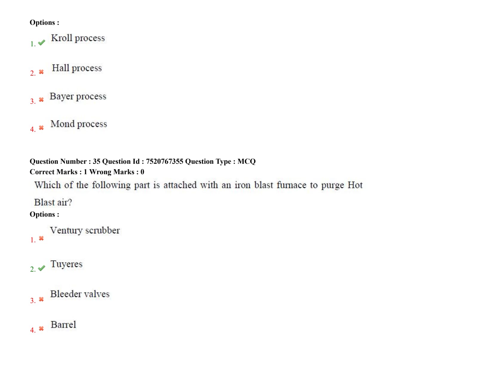
Titanium extraction commonly involves
Detailed Solution
Step 1: Understanding the Question:
The question asks to identify the standard industrial process used for the extraction of metallic titanium.
Step 2: Key Formula or Approach:
Titanium is highly reactive and cannot be reduced by carbon because it easily forms stable titanium carbides.
Instead, the Kroll process relies on the pyrometallurgical reduction of titanium tetrachloride (\( TiCl_4 \)) using metallic magnesium under an inert argon atmosphere.
Step 3: Detailed Explanation:
Reaction Steps in the Kroll Process:
1. Carbothermic Chlorination: Titanium dioxide (rutile ore) is converted to volatile titanium tetrachloride at \( 1000^\circC \) in the presence of carbon and chlorine gas:
\[ TiO_2 + 2C + 2Cl_2 \rightarrow TiCl_4 + 2CO \]
2. Purification: The liquid \( TiCl_4 \) is purified by fractional distillation.
3. Magnesiothermic Reduction: Highly purified \( TiCl_4 \) vapor is introduced into a reactor containing liquid magnesium at \( 800^\circC to 850^\circC \) under a protective argon atmosphere:
\[ TiCl_4(g) + 2Mg(l) \rightarrow Ti(s) + 2MgCl_2(l) \]
The resulting titanium is produced as a porous mass called titanium sponge.
Analysis of Other Options:
- Hall process (Option B) is the electrolytic reduction process for aluminium.
- Bayer process (Option C) is the hydrometallurgical purification of bauxite to produce alumina.
- Mond process (Option D) is the carbonyl process used for refining nickel.
Step 4: Final Answer:
Hence, titanium extraction commonly involves the Kroll process, which corresponds to Option (A).
Quick Tip: The Kroll process is highly energy-intensive and operated in batches because the titanium sponge must be vacuum-distilled to remove excess magnesium and magnesium chloride.
Which of the following part is attached with an iron blast furnace to purge Hot Blast air?
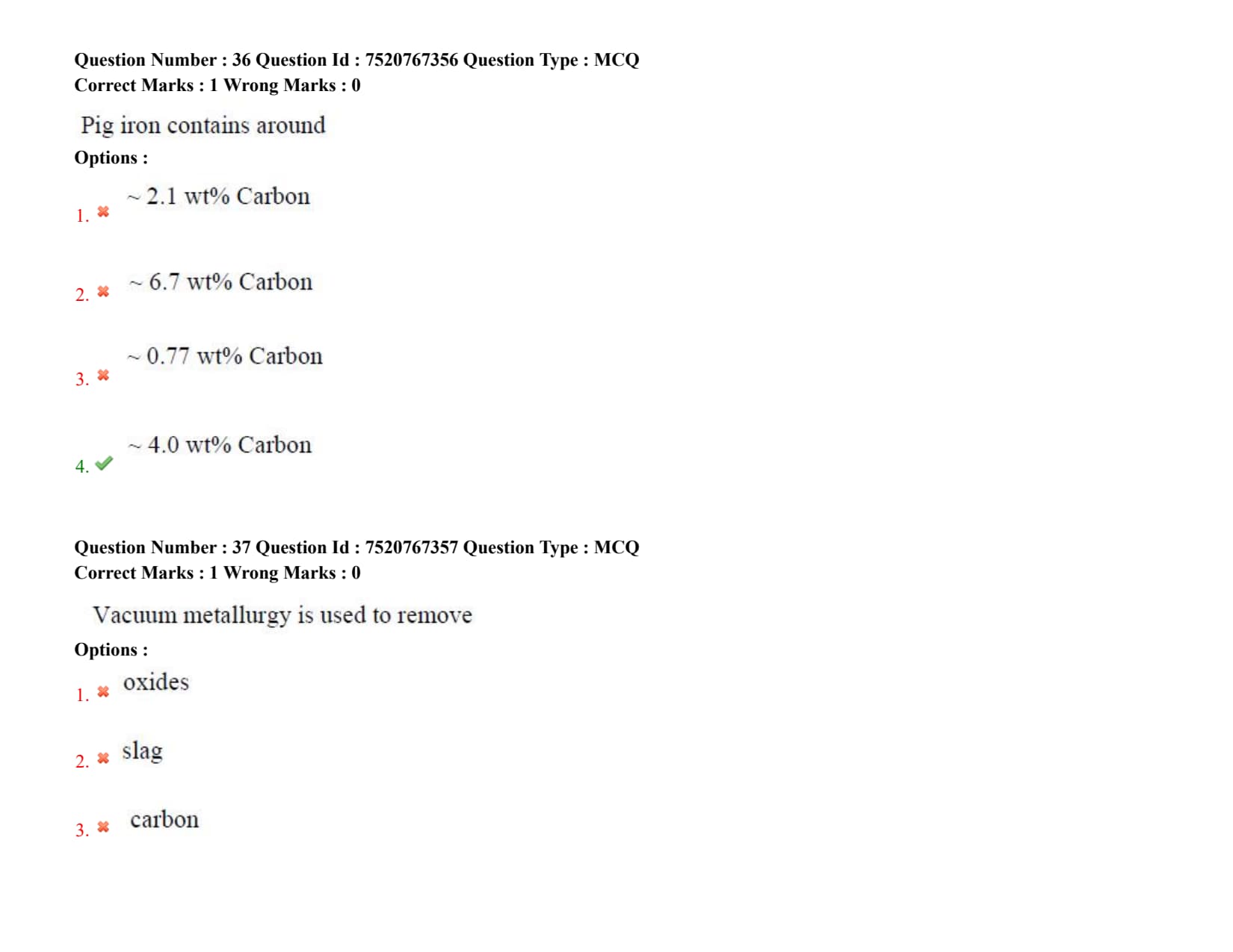
Pig iron contains around
Detailed Solution
Step 1: Understanding the Question:
The question asks for the typical weight percentage of carbon present in pig iron, which is the immediate liquid iron product tapped from an ironmaking blast furnace.
Step 2: Key Formula or Approach:
Liquid iron in the blast furnace hearth is in direct, prolonged contact with solid carbon (coke) at high temperatures (\( > 1400^\circC \)).
As a result, the liquid metal becomes saturated with carbon according to the solubility limit of carbon in liquid iron at that temperature.
Step 3: Detailed Explanation:
High Carbon Saturation: Liquid iron in the blast furnace absorbs carbon until it reaches saturation, which is typically around \( 4.0 to 4.5 wt% \) carbon at operating temperatures.
This high carbon content lowers the melting point of the alloy to approximately \( 1150^\circC to 1200^\circC \) (near the Fe-C eutectic temperature), allowing the liquid iron to be easily tapped and handled.
Impurity Levels: In addition to carbon, pig iron contains significant concentrations of other impurities reduced from the ore and flux:
- Silicon (\( \sim 0.5 to 1.5 wt% \))
- Manganese (\( \sim 0.5 to 1.0 wt% \))
- Phosphorus (\( \sim 0.1 to 1.5 wt% \))
- Sulfur (\( \sim 0.03 to 0.08 wt% \))
Comparison with Other Options:
- \( 0.7 wt% \) (Option C) represents typical medium/high-carbon steels.
- \( 2.1 wt% \) (Option A) is the maximum solubility limit of carbon in austenite, marking the theoretical boundary between steel and cast iron.
- \( 6.7 wt% \) (Option B) corresponds to stoichiometric cementite (\( Fe_3C \)), which is highly brittle and not achieved in standard liquid iron output.
Step 4: Final Answer:
Therefore, pig iron contains around \( 4.0 wt% \) carbon, which corresponds to Option (D).
Quick Tip: Because of its high carbon content, pig iron is extremely brittle and cannot be forged or rolled directly. It must be refined to reduce carbon levels to produce steel.
Vacuum metallurgy is used to remove
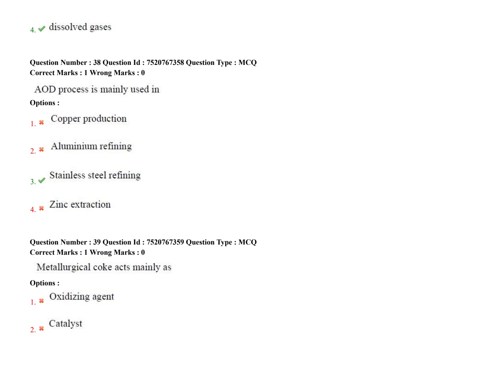
AOD process is mainly used in
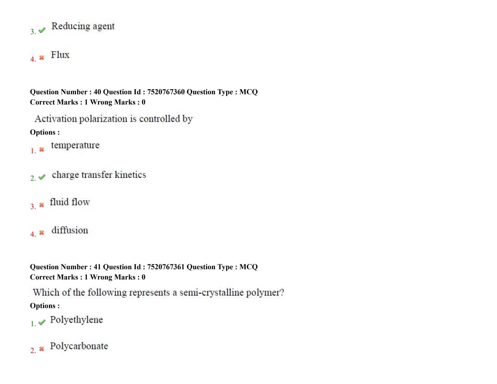
Metallurgical coke acts mainly as
Detailed Solution
Step 1: Understanding the Question:
The question asks for the primary chemical role played by metallurgical coke in the extraction of iron within a blast furnace.
Step 2: Key Formula or Approach:
Inside the blast furnace, hematite (\( Fe_2O_3 \)) must be reduced to metallic iron.
Coke reacts with oxygen to generate carbon monoxide gas:
\[ 2C + O_2 \rightarrow 2CO \]
This carbon monoxide then acts as the primary gaseous reducing agent to reduce iron oxides:
\[ Fe_2O_3 + 3CO \rightarrow 2Fe + 3CO_2 \]
Step 3: Detailed Explanation:
Three Roles of Coke: Metallurgical coke plays three vital roles in the blast furnace:
1. Chemical Role (Reducing Agent): It reacts to produce \( CO \), which serves as the reducing agent. Carbon from coke also directly reduces silicon, manganese, and phosphorus in the hearth.
2. Thermal Role (Fuel): The combustion of coke at the tuyere level provides the high temperatures required for endothermic reactions and melting of iron and slag.
3. Physical Role (Permeable Support): Coke is the only material that remains solid and strong in the high-temperature cohesive zone of the blast furnace. It provides a highly permeable grid that supports the raw materials while allowing gases to rise and liquid iron/slag to drain.
Analysis of Other Options:
- Coke is not an oxidizing agent (Option A); its purpose is to remove oxygen, not supply it.
- It is a reactant consumed in large quantities, not a catalyst (Option B).
- Fluxes (Option D, like limestone) are added to remove ash and form slag, which is a different chemical function.
Step 4: Final Answer:
Hence, metallurgical coke acts mainly as a reducing agent, corresponding to Option (C).
Quick Tip: The coke rate in modern blast furnaces is a key performance metric. Minimizing it through the injection of auxiliary fuels through the tuyeres reduces both steel production costs and carbon dioxide emissions.
Activation polarization is controlled by
Detailed Solution
Step 1: Understanding the Question:
The question asks to identify the rate-controlling step or factor associated with activation polarization in electrochemistry and corrosion.
Step 2: Key Formula or Approach:
The relationship between activation polarization overpotential (\( \eta_{act} \)) and current density (\( i \)) is mathematically described by the Tafel equation:
\[ \eta_{act} = \pm \beta \log\left(\frac{i}{i_0}\right) \]
where:
\( \beta \) is the Tafel slope, and
\( i_0 \) is the exchange current density.
Step 3: Detailed Explanation:
Definition of Activation Polarization: Activation polarization refers to an electrochemical reaction rate that is limited by an inherent, slow step in the reaction sequence at the metal-electrolyte interface.
This slow step requires an energy barrier (activation energy) to be overcome.
Charge Transfer Rate-Limiting Step: The rate-determining step is typically the transfer of electrons (charge transfer) between the electrode and the reacting species, or the adsorption/desorption of species on the electrode surface.
Therefore, activation polarization is fundamentally controlled by charge transfer kinetics.
Comparison with Concentration Polarization:
- Diffusion and fluid flow (Options C and D) control concentration polarization, where the reaction rate is limited by the mass transport of reactants to or products away from the electrode surface.
- Although temperature (Option A) influences reaction rates, it is an environmental variable rather than the physical mechanism controlling the polarization class.
Step 4: Final Answer:
Thus, activation polarization is controlled by charge transfer kinetics, matching Option (B).
Quick Tip: Hydrogen evolution on iron is a classic example of an activation-controlled reaction, where the slow step is the formation of diatomic hydrogen molecules from adsorbed hydrogen atoms on the metal surface.
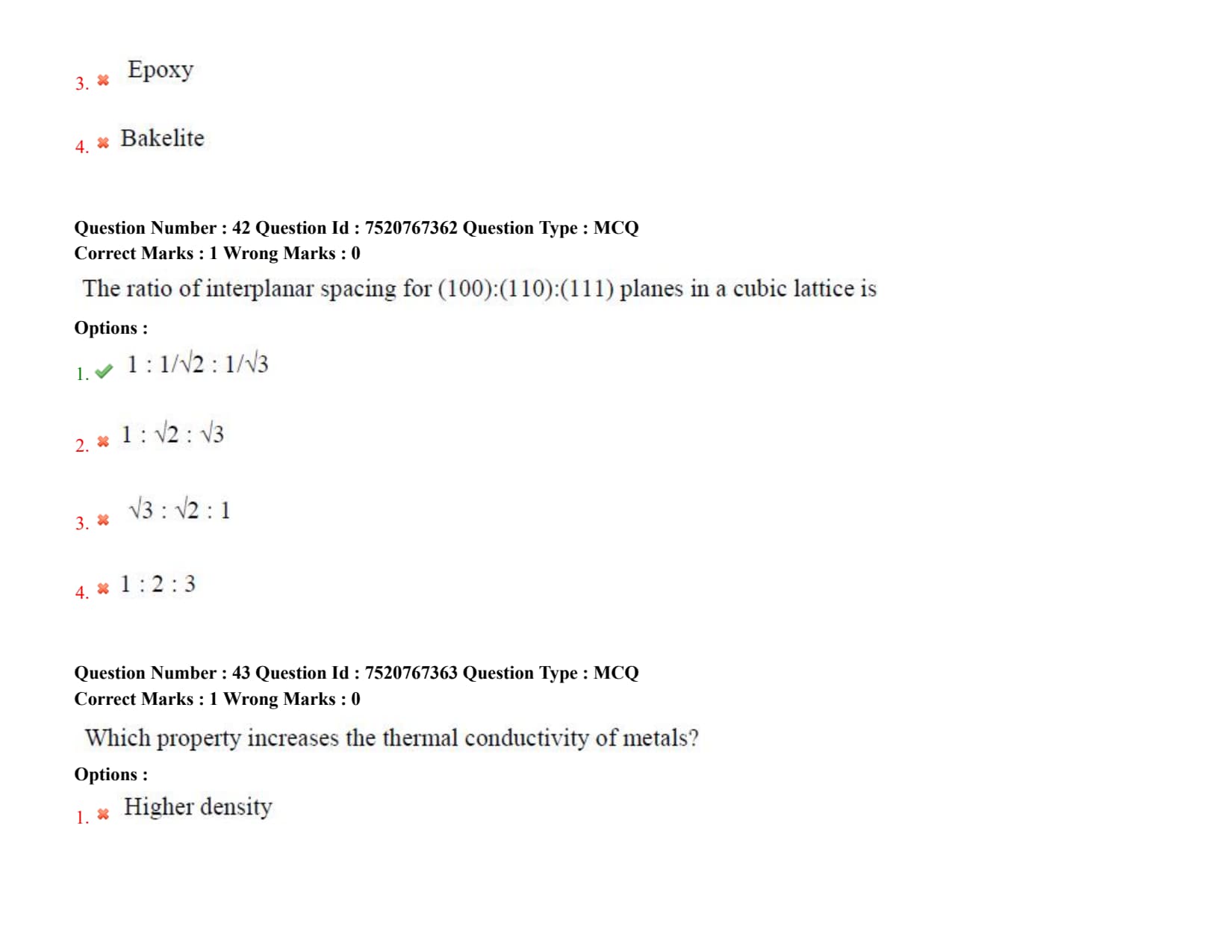
Which of the following represents a semi-crystalline polymer?
The ratio of interplanar spacing for (100):(110):(111) planes in a cubic lattice is
Detailed Solution
Step 1: Understanding the Question:
The question asks for the mathematical ratio of the interplanar spacing (\( d_{hkl} \)) for the low-index planes (100), (110), and (111) in a standard cubic crystal system.
Step 2: Key Formula or Approach:
For any cubic crystal system with a lattice parameter \( a \), the interplanar spacing \( d_{hkl} \) of a plane with Miller indices \( (hkl) \) is given by:
\[ d_{hkl} = \frac{a}{\sqrt{h^2 + k^2 + l^2}} \]
Step 3: Detailed Explanation:
Calculation of Spacing for (100) Plane:
Using \( h=1, k=0, l=0 \):
\[ d_{100} = \frac{a}{\sqrt{1^2 + 0^2 + 0^2}} = a \]
Calculation of Spacing for (110) Plane:
Using \( h=1, k=1, l=0 \):
\[ d_{110} = \frac{a}{\sqrt{1^2 + 1^2 + 0^2}} = \frac{a}{\sqrt{2}} \]
Calculation of Spacing for (111) Plane:
Using \( h=1, k=1, l=1 \):
\[ d_{111} = \frac{a}{\sqrt{1^2 + 1^2 + 1^2}} = \frac{a}{\sqrt{3}} \]
Determining the Ratio:
The ratio of their interplanar spacings \( d_{100} : d_{110} : d_{111} \) can be written as:
\[ d_{100} : d_{110} : d_{111} = a : \frac{a}{\sqrt{2}} : \frac{a}{\sqrt{3}} \]
Factoring out the lattice parameter \( a \) yields:
\[ d_{100} : d_{110} : d_{111} = 1 : \frac{1}{\sqrt{2}} : \frac{1}{\sqrt{3}} \]
Step 4: Final Answer:
Thus, the correct ratio of interplanar spacing is \( 1 : 1/\sqrt{2} : 1/\sqrt{3} \), matching Option (A).
Quick Tip: In a cubic system, as the Miller indices \( h, k, l \) increase, the interplanar spacing \( d_{hkl} \) decreases. Therefore, the (100) plane will always have a larger spacing than the (110) and (111) planes.
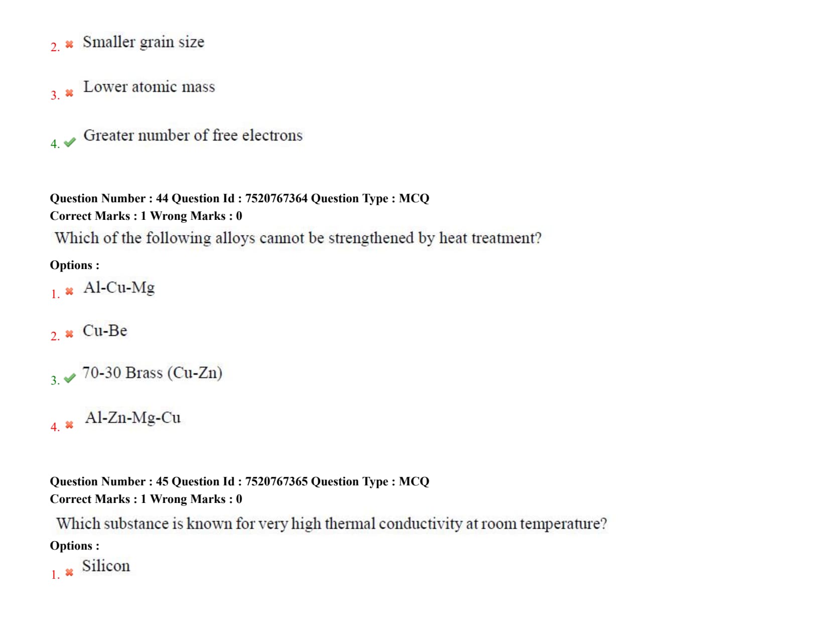
Which property increases the thermal conductivity of metals?
Which of the following alloys cannot be strengthened by heat treatment?
Detailed Solution
Step 1: Understanding the Question:
The question asks to identify the alloy among the choices that cannot be strengthened by thermal processing (heat treatment), such as precipitation hardening or martensitic transformation.
Step 2: Detailed Explanation:
Precipitation Hardening Alloys: Alloys like Al-Cu-Mg (Option A, duralumin), Cu-Be (Option B, beryllium copper), and Al-Zn-Mg-Cu (Option D, 7000-series aerospace aluminium) are classic age-hardenable alloys.
These alloys are strengthened by solutionizing (heating to form a single-phase solid solution), quenching to form a supersaturated solid solution, and aging (heating to precipitate fine, coherent secondary phases that block dislocation motion).
Structure of 70-30 Brass: 70-30 Brass (Option C, cartridge brass) is a single-phase alpha brass containing \( 70% \) Copper and \( 30% \) Zinc.
The copper-zinc binary phase diagram shows that zinc remains completely dissolved in the alpha (\( fcc \)) solid solution at all temperatures below \( 400^\circC \) for this composition.
Since there is no change in solid solubility with decreasing temperature, second-phase precipitation cannot occur.
Furthermore, brass does not undergo any shear-induced martensitic phase transformations.
Strengthening of Brass: Consequently, single-phase 70-30 brass can only be strengthened by cold working (strain hardening) or solid-solution strengthening.
Heat treatment of cold-worked brass only causes recovery, recrystallization, and grain growth, which softens the material rather than strengthening it.
Step 3: Final Answer:
Thus, 70-30 Brass (Cu-Zn) cannot be strengthened by heat treatment, corresponding to Option (C).
Quick Tip: For an alloy to be strengthenable by precipitation hardening (aging), it must exhibit a decreasing solid-solubility limit with decreasing temperature on its phase diagram.
Which substance is known for very high thermal conductivity at room temperature?
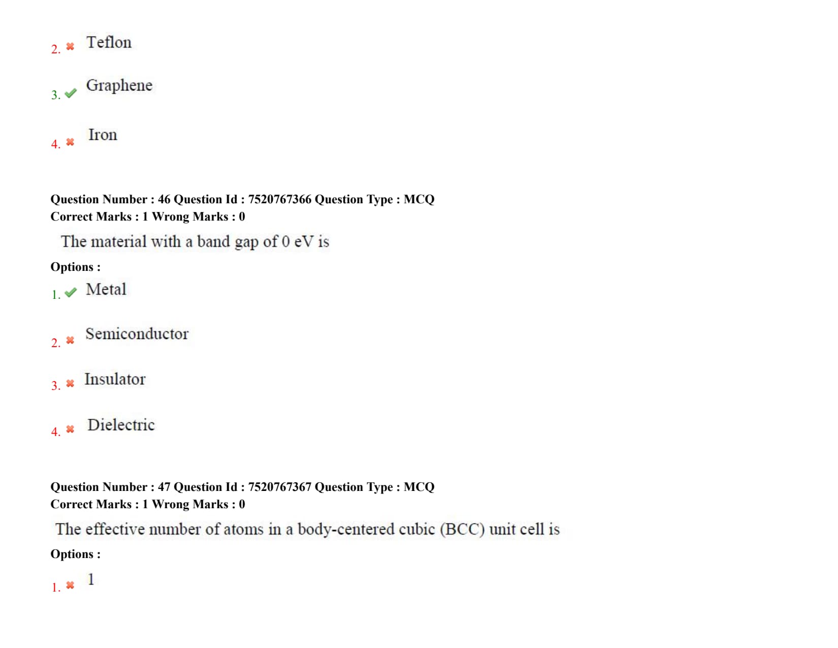
The material with a band gap of 0 eV is
The effective number of atoms in a body-centered cubic (BCC) unit cell is
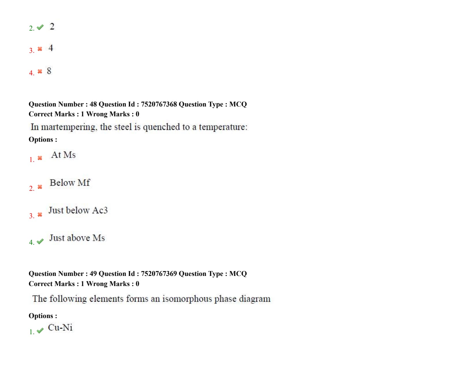
In martempering, the steel is quenched to a temperature:
Detailed Solution
Step 1: Understanding the Question:
The question asks for the target temperature to which steel is quenched during the martempering heat treatment process.
Step 2: Detailed Explanation:
Purpose of Martempering: Martempering (or marquenching) is a specialized heat treatment designed to minimize thermal distortion, internal stresses, and cracking in high-hardenability steels during martensitic transformation.
Process Steps:
1. The steel is first austenitized above its critical temperature (\( Ac_3 \)).
2. It is then rapidly quenched in a hot salt bath or oil bath maintained at a temperature just above the martensite start temperature (\( M_s \)).
3. The steel is held at this temperature long enough to allow the temperature profile across the entire cross-section (from core to surface) to become uniform, without allowing bainite to form.
4. Finally, the steel is removed from the bath and cooled slowly in air to room temperature. This slow cooling rate allows martensite to form uniformly throughout the part.
Analysis of Incorrect Options:
- Quenching directly to \( M_s \) (Option A) or below \( M_f \) (Option B) would cause premature, non-uniform martensite formation during the isothermal holding stage, defeating the purpose of temperature equalization.
- Quenching to just below \( Ac_3 \) (Option C) would result in high-temperature ferrite/pearlite transformations, failing to produce martensite.
Step 3: Final Answer:
Hence, in martempering, steel is quenched to a temperature just above Ms, which corresponds to Option (D).
Quick Tip: The key to martempering is achieving a uniform temperature distribution throughout the part \textbf{before} the martensitic transformation begins. This dramatically reduces the risk of quench cracking.
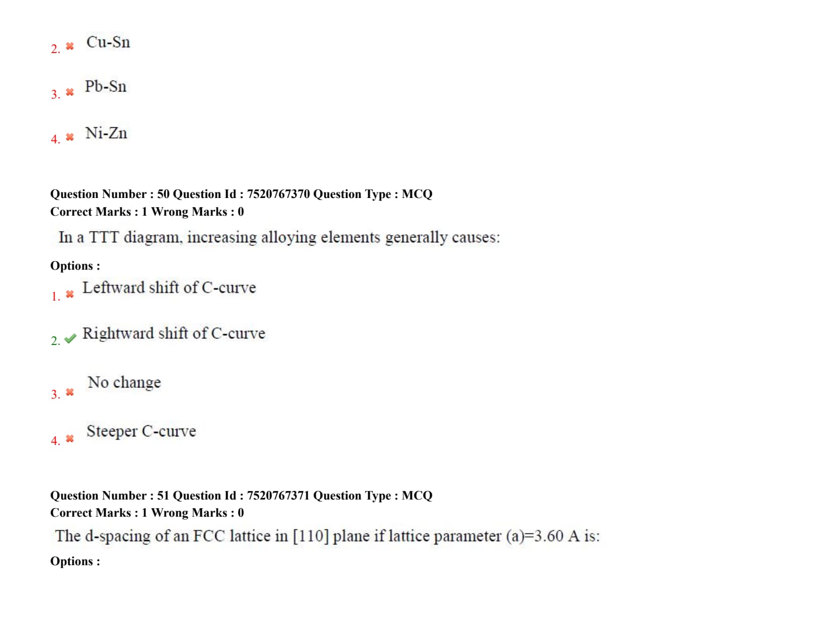
The following elements forms an isomorphous phase diagram
Detailed Solution
Step 1: Understanding the Question:
The question asks to identify which alloy system forms a completely isomorphous binary phase diagram.
An isomorphous system is one in which the two components are completely soluble in each other in both the liquid and solid states across the entire composition range.
Step 2: Detailed Explanation:
Criteria for Solid Solubility: According to the Hume-Rothery rules, complete solid solubility between two elements requires:
1. The atomic radius difference must be less than \( 15% \).
2. They must have the same crystal structure.
3. They should have similar electronegativities.
4. They must have similar valencies.
The Copper-Nickel (Cu-Ni) System:
- Both Copper (\( Cu \)) and Nickel (\( Ni \)) have an FCC crystal structure.
- Their atomic radii are very similar (\( r_{Cu} = 0.128 nm \) and \( r_{Ni} = 0.125 nm \), a difference of only \( \sim 2.3% \)).
- Their electronegativities and valencies are also very close.
- Consequently, the Cu-Ni system satisfies all Hume-Rothery rules and forms a classic, lens-shaped isomorphous phase diagram consisting of only liquid (\( L \)), solid (\( \alpha \)), and two-phase (\( L+\alpha \)) fields.
Other Systems:
- Cu-Sn (Option B) and Ni-Zn (Option D) form complex phase diagrams with several intermetallic phases.
- Pb-Sn (Option C) is a classic eutectic system with limited solid solubility.
Step 3: Final Answer:
Therefore, the Cu-Ni system forms an isomorphous phase diagram, matching Option (A).
Quick Tip: Copper-Nickel (monel/cupronickel) is the most famous example of a binary isomorphous system. Another common example is the Gold-Silver (Au-Ag) system.
In a TTT diagram, increasing alloying elements generally causes:
Detailed Solution
Step 1: Understanding the Question:
The question asks how the addition of alloying elements (excluding cobalt) affects the position of the transformation start curves (C-curves) on a Time-Temperature-Transformation (TTT) diagram of steel.
Step 2: Detailed Explanation:
TTT Diagram C-Curve: The C-curve on a TTT diagram represents the start and finish times of diffusional phase transformations (such as austenite to pearlite or bainite) at different isothermal temperatures.
The "nose" of the C-curve corresponds to the minimum time required for these transformations to begin.
Effect of Alloying Elements: Alloying elements (such as Chromium, Nickel, Manganese, and Molybdenum) dissolve in austenite and stabilize it.
These solute atoms slow down the diffusion of carbon, which is required for pearlite and bainite nucleation and growth.
Because diffusion is hindered, the time required for these phase transformations to start increases significantly.
This causes the C-curves to shift to the right (toward longer times).
Hardenability Significance: A rightward shift of the C-curve means that slower cooling rates can be used during quenching to bypass the pearlite/bainite nose and form martensite.
This significantly increases the hardenability of the steel.
Exceptions: Cobalt is a notable exception; it increases the rate of nucleation of pearlite and shifts the C-curve to the left. However, almost all other common alloying elements shift it to the right.
Step 3: Final Answer:
Thus, increasing alloying elements generally causes a rightward shift of the C-curve, which is Option (B).
Quick Tip: A rightward shift of the TTT C-curve directly increases the critical cooling rate's margin, making it easier to fully harden thick sections of steel without forming soft pearlite.
The d-spacing of an FCC lattice in [110] plane if lattice parameter (a)=3.60 A is:
Detailed Solution
Step 1: Understanding the Question:
The question asks to calculate the interplanar d-spacing (\( d_{hkl} \)) for the (110) plane family in a face-centered cubic (\( FCC \)) crystal lattice with a given lattice parameter \( a = 3.60 \AA \).
Note: The question uses the notation [110], which typically represents a direction, but the context clearly refers to the (110) crystallographic plane.
Step 2: Key Formula or Approach:
The interplanar spacing \( d_{hkl} \) for a cubic system is calculated using the standard formula:
\[ d_{hkl} = \frac{a}{\sqrt{h^2 + k^2 + l^2}} \]
Step 3: Detailed Explanation:
Substituting the Values:
Given lattice parameter: \( a = 3.60 \AA \)
Miller indices of the plane: \( h = 1, k = 1, l = 0 \)
Calculation:
\[ d_{110} = \frac{3.60 \AA}{\sqrt{1^2 + 1^2 + 0^2}} \]
\[ d_{110} = \frac{3.60 \AA}{\sqrt{1 + 1 + 0}} = \frac{3.60 \AA}{\sqrt{2}} \]
Knowing that \( \sqrt{2} \approx 1.4142 \):
\[ d_{110} \approx \frac{3.60}{1.4142} \approx 2.5456 \AA \]
Rounding this value to two decimal places gives \( 2.55 \AA \).
Step 4: Final Answer:
Therefore, the interplanar d-spacing is approximately 2.55 \AA, matching Option (A).
Quick Tip: Always ensure that you use the correct plane indices in the denominator. The formula remains identical for SC, BCC, and FCC systems, but the allowed reflections in XRD will depend on the extinction rules of each lattice.
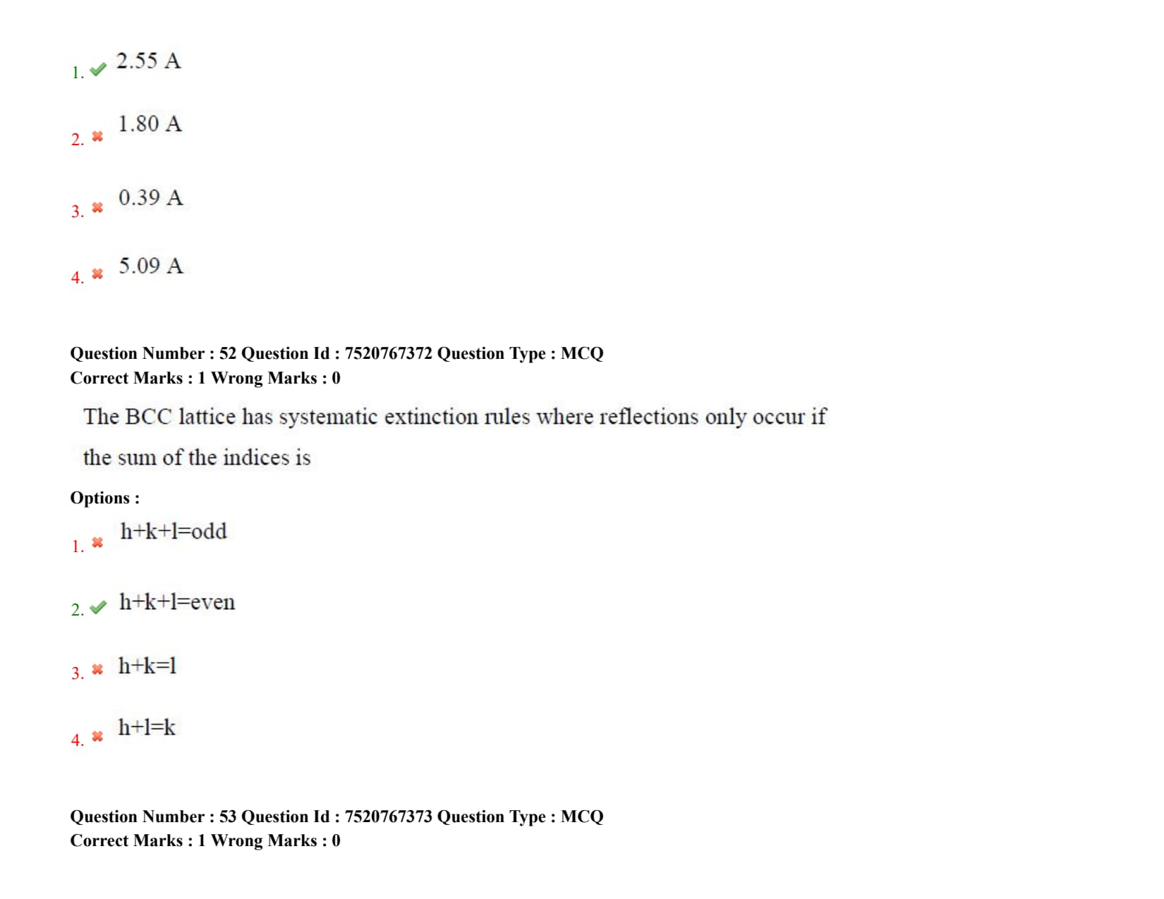
The BCC lattice has systematic extinction rules where reflections only occur if the sum of the indices is
Detailed Solution
Step 1: Understanding the Question:
The question asks for the systematic extinction (or reflection) rule that determines which crystallographic planes \( (hkl) \) can produce X-ray diffraction peaks in a body-centered cubic (\( BCC \)) crystal structure.
Step 2: Key Formula or Approach:
The structure factor \( F_{hkl} \) for a unit cell determines the intensity of a diffracted beam:
\[ F_{hkl} = \sum_{j} f_j \exp\left[ 2\pi i (h x_j + k y_j + l z_j) \right] \]
For a BCC unit cell with two identical atoms located at fractional coordinates \( (0,0,0) \) and \( (1/2, 1/2, 1/2) \), this equation simplifies to:
\[ F_{hkl} = f \left( 1 + e^{\pi i (h+k+l)} \right) \]
Step 3: Detailed Explanation:
Mathematical Conditions:
- If the sum \( h+k+l \) is an even integer, then \( e^{\pi i (h+k+l)} = e^{even\cdot\pi i} = 1 \). This gives a non-zero structure factor:
\[ F_{hkl} = f(1 + 1) = 2f \quad \rightarrow \quad I \propto |F_{hkl}|^2 = 4f^2 \]
Therefore, diffraction can occur, and a reflection peak will be observed.
- If the sum \( h+k+l \) is an odd integer, then \( e^{\pi i (h+k+l)} = e^{odd\cdot\pi i} = -1 \). This results in a structure factor of zero:
\[ F_{hkl} = f(1 - 1) = 0 \quad \rightarrow \quad I \propto |F_{hkl}|^2 = 0 \]
This leads to complete destructive interference, and no diffraction peak is observed (systematic extinction).
First Allowed Planes: The first few planes that produce reflections in a BCC crystal are (110), (200), (211), and (220). Planes like (100) or (111) are extinct because their sum of indices is odd.
Step 4: Final Answer:
Hence, for a BCC lattice, reflections only occur if \( h+k+l = even \), which corresponds to Option (B).
Quick Tip: Remember the systematic reflection rules for common cubic systems:
- BCC: \( h+k+l = even \)
- FCC: \( h, k, l \) must be all even or all odd (mixed indices are extinct)
- Simple Cubic: All planes can diffract (no systematic extinctions)
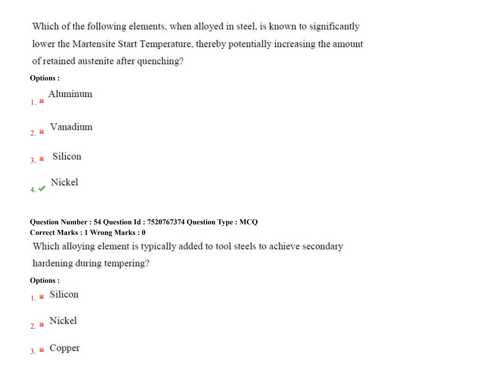
Which of the following elements, when alloyed in steel, is known to significantly lower the Martensite Start Temperature, thereby potentially increasing the amount of retained austenite after quenching?
Which alloying element is typically added to tool steels to achieve secondary hardening during tempering?
Detailed Solution
Step 1: Understanding the Question:
The question asks to identify the alloying element that is added to tool steels to promote the phenomenon of secondary hardening during the tempering process.
Step 2: Detailed Explanation:
Mechanism of Secondary Hardening: When standard carbon steels are tempered, they continuously soften as temperature increases due to the coarsening of iron carbides (\( Fe_3C \)) and recovery of the dislocation structure.
However, in tool steels containing strong carbide-forming elements (like Molybdenum, Tungsten, Vanadium, and Chromium), a different behavior is observed at high tempering temperatures (\( 500^\circC to 600^\circC \)).
- At these elevated temperatures, alloy elements like Molybdenum become mobile enough to diffuse through the lattice.
- They react with carbon to form extremely fine, highly stable, and coherent alloy carbides (such as \( Mo_2C \) or \( MC \)).
- These fine alloy carbides replace the coarser iron carbides, pinning dislocations and causing an increase in hardness. This phenomenon is known as secondary hardening (or red hardness).
Role of Other Elements:
- Silicon (Option A) retards tempering and prevents softening at low temperatures but does not form secondary carbides.
- Nickel (Option B) and Copper (Option C) are non-carbide-forming elements in steel and do not contribute to secondary hardening through carbide precipitation.
Step 3: Final Answer:
Hence, Molybdenum is typically added to tool steels to achieve secondary hardening, corresponding to Option (D).
Quick Tip: Secondary hardening is essential for high-speed tool steels (like the M-series containing Molybdenum) because it allows the tools to maintain their cutting edge and hardness even when they heat up to red-hot temperatures during high-speed machining.
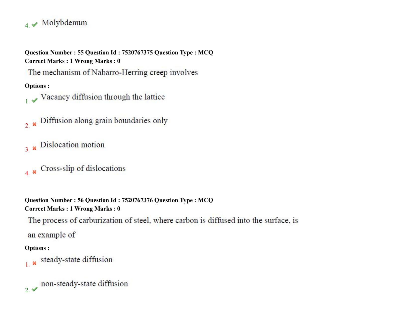
The mechanism of Nabarro-Herring creep involves
Detailed Solution
Step 1: Understanding the Question:
The question asks for the underlying atomic transport mechanism that drives Nabarro-Herring creep in materials at high temperatures.
Step 2: Key Formula or Approach:
Creep is the slow, progressive, and permanent deformation of a material over time under constant stress at elevated temperatures (\( T > 0.4 T_m \)).
The strain rate (\( \dot{\epsilon} \)) for Nabarro-Herring creep is given by:
\[ \dot{\epsilon}_{NH} \propto \frac{\sigma \cdot D_L}{d^2} \]
where:
\( \sigma \) is the applied stress,
\( D_L \) is the lattice (bulk) diffusion coefficient, and
\( d \) is the grain size.
Step 3: Detailed Explanation:
Nabarro-Herring Creep Mechanism: This mechanism occurs at very high temperatures (\( T > 0.6 T_m \)) and relatively low stresses.
Under an applied tensile stress, grain boundaries perpendicular to the tensile axis experience tensile stress, which lowers the vacancy formation energy, while boundaries parallel to the tensile axis experience compressive stress.
This creates a vacancy concentration gradient:
- Vacancies migrate through the bulk crystal lattice from regions of high concentration (tensile boundaries) to regions of low concentration (compressive boundaries).
- Atoms migrate in the opposite direction (from compressive to tensile boundaries), resulting in elongation of the grains along the tensile axis.
Coble Creep Comparison: Diffusion along grain boundaries only (Option B) is the mechanism of Coble creep, which is dominant at lower temperatures because the activation energy for grain boundary diffusion is lower than that for bulk lattice diffusion.
- The strain rate for Coble creep is proportional to \( 1/d^3 \).
Dislocation Creep: Dislocation motion (Option C) and cross-slip (Option D) are active at higher stresses, where dislocation climb and glide dominate the deformation process.
Step 4: Final Answer:
Therefore, Nabarro-Herring creep involves vacancy diffusion through the lattice, matching Option (A).
Quick Tip: Because both Nabarro-Herring and Coble creep strain rates are inversely proportional to grain size (\( 1/d^2 \) and \( 1/d^3 \)), materials with very large grains or single-crystal structures (like turbine blades) are highly resistant to diffusional creep.
The process of carburization of steel, where carbon is diffused into the surface, is an example of
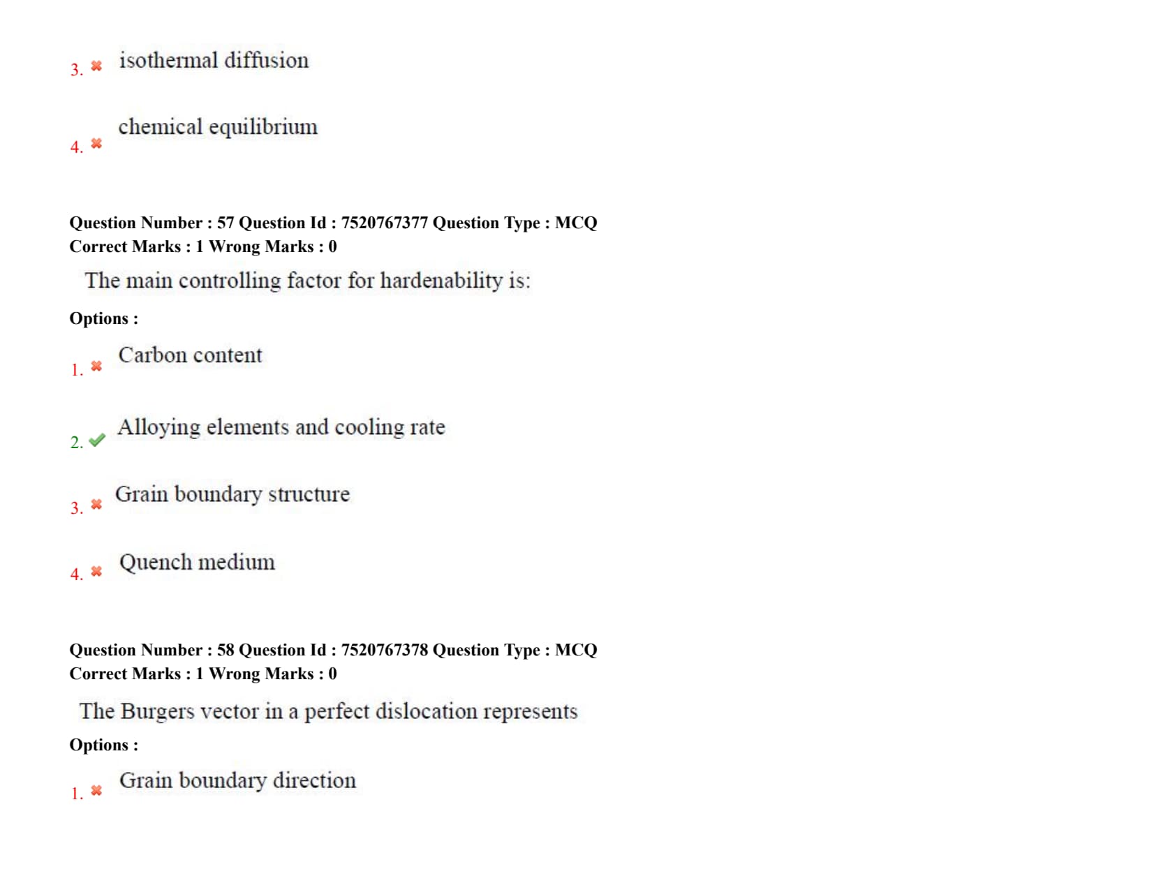
The main controlling factor for hardenability is:
Detailed Solution
Step 1: Understanding the Question:
The question asks for the primary variables that control the hardenability of steel.
Hardenability is the ability of a steel alloy to transform into martensite throughout its cross-section upon quenching from the austenitizing temperature. It should not be confused with hardness, which is the resistance to plastic deformation.
Step 2: Detailed Explanation:
Role of Alloying Elements: The most critical material factor controlling hardenability is the presence and concentration of dissolved alloying elements (excluding Cobalt) in austenite.
Alloying elements like Chromium, Manganese, Nickel, and Molybdenum delay the diffusional decomposition of austenite into pearlite or bainite by slowing down carbon diffusion. This shifts the C-curves of the TTT/CCT diagrams to the right, making it easier to form martensite at slower cooling rates.
Role of Cooling Rate: The cooling rate is the primary process variable. To achieve a fully martensitic structure, the actual cooling rate at any point within the part must exceed the critical cooling rate of the steel.
The critical cooling rate is determined by the alloy composition. Together, the alloying elements (which determine the chemistry) and the cooling rate (which is determined by the quench medium and part geometry) control the depth and distribution of hardness.
Carbon Content vs. Hardenability: Carbon content (Option A) determines the maximum hardness that can be achieved in the martensitic state, but it does not control the depth of hardening (hardenability) as effectively as alloy additions.
- Quench medium (Option D) affects the heat extraction rate, but hardenability itself is an intrinsic material capability of the steel. However, the official answer key groups "Alloying elements and cooling rate" together as the primary combined controlling factor.
Step 3: Final Answer:
According to the official exam key, the main controlling factor for hardenability is alloying elements and cooling rate, matching Option (B).
Quick Tip: The Jominy End-Quench test is the standard experimental method used to measure and compare the hardenability of different steel alloys.
The Burgers vector in a perfect dislocation represents
Detailed Solution
Step 1: Understanding the Question:
The question asks for the physical definition and significance of the Burgers vector (\( \vec{b} \)) associated with a perfect dislocation in a crystal lattice.
Step 2: Detailed Explanation:
Definition of Burgers Vector: The Burgers vector (\( \vec{b} \)) is a fundamental vector that characterizes a dislocation.
It represents the magnitude and direction of the lattice distortion (or slip distance) associated with the dislocation line.
Burgers Circuit Method: The Burgers vector is determined by constructing a closed loop (Burgers circuit) around the dislocation line in a real, distorted crystal, and comparing it to an identical loop made in a perfect, defect-free crystal.
The vector required to close the loop in the perfect crystal is the Burgers vector.
Dislocation Types:
- In an edge dislocation, the Burgers vector is perpendicular to the dislocation line (\( \vec{b} \perp \vec{t} \)).
- In a screw dislocation, the Burgers vector is parallel to the dislocation line (\( \vec{b} \parallel \vec{t} \)).
- In a perfect (or unit) dislocation, the magnitude of the Burgers vector is equal to one repeat distance of the crystal lattice in that crystallographic direction.
Analysis of Incorrect Options:
- It does not represent grain boundary direction (Option A), crystal orientation (Option C), or the normal to the slip plane (Option D, which is defined by the cross product of the dislocation line vector and the Burgers vector).
Step 3: Final Answer:
Therefore, the Burgers vector represents the magnitude and direction of lattice distortion, matching Option (B).
Quick Tip: The elastic strain energy per unit length of a dislocation is proportional to the square of its Burgers vector (\( E \propto G b^2 \)). This explains why dislocations split into partial dislocations to minimize their energy.
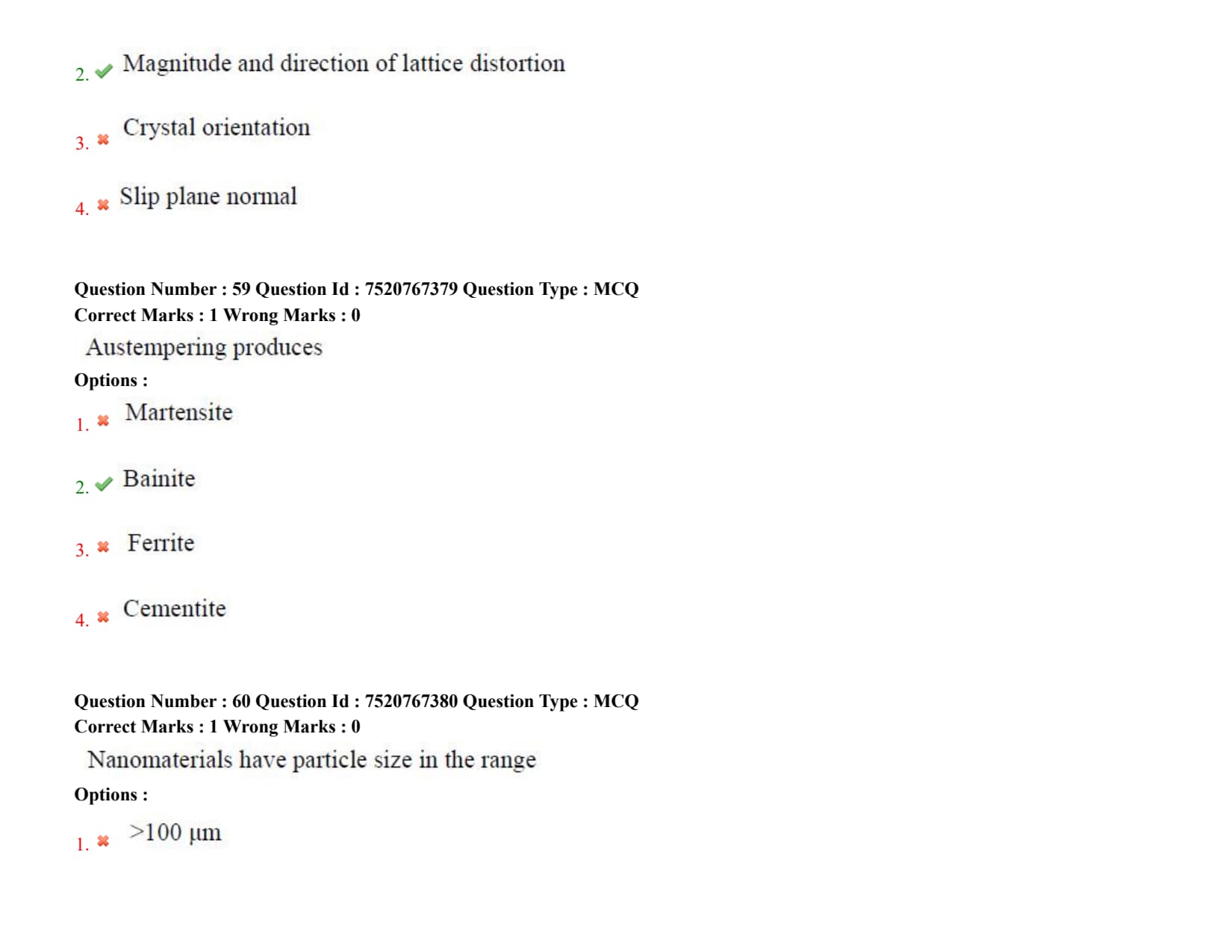
Austempering produces
Detailed Solution
Step 1: Understanding the Question:
The question asks to identify the microstructural constituent produced in steel by the austempering heat treatment process.
Step 2: Detailed Explanation:
Definition of Austempering: Austempering is an isothermal heat treatment process designed to produce a fully bainitic microstructure in carbon and low-alloy steels.
Bainite is a microstructural phase consisting of a fine, plate-like mixture of ferrite and cementite that offers an excellent combination of high strength, toughness, and impact resistance.
Process Steps:
1. The steel is heated into the single-phase austenite region to achieve complete austenitization.
2. It is then rapidly quenched in a hot bath (usually molten salt) maintained at a temperature below the pearlite-forming range but above the martensite start temperature (\( M_s \)), typically between \( 250^\circC and 450^\circC \).
3. The steel is held isothermally at this temperature long enough for the austenite to transform completely into bainite (either upper or lower bainite, depending on the temperature).
4. Finally, it is cooled to room temperature.
Comparison with Martensite: Unlike conventional quenching which produces brittle martensite (Option A) that requires tempering, austempering directly produces tough bainite. This eliminates the need for a separate tempering step and reduces the risk of thermal cracking and distortion.
Step 3: Final Answer:
Thus, austempering produces bainite, which corresponds to Option (B).
Quick Tip: Lower bainite, formed at lower austempering temperatures (closer to \( M_s \)), has a finer needle-like structure and exhibits superior yield strength and toughness compared to upper bainite.
Nanomaterials have particle size in the range
Detailed Solution
Step 1: Understanding the Question:
The question asks for the standard dimensional size range that defines a material as a nanomaterial.
Step 2: Detailed Explanation:
Defining Nanomaterials: In materials science and nanotechnology, a nanomaterial is formally defined as any natural, incidental, or manufactured material containing particles where at least one external dimension falls within the nanoscale.
- The nanoscale is universally defined as the range from 1 to 100 nanometers (\( nm \)).
- One nanometer is equal to one-billionth of a meter (\( 10^{-9} m \)).
Unique Properties of Nanoscale Materials: When particle dimensions are reduced to the 1-100 nm range, materials begin to exhibit unique physical, chemical, optical, and mechanical properties.
These novel properties arise due to two main phenomena:
1. Quantum Confinement Effects: At very small scales, the electronic and optical properties of materials deviate significantly from those of bulk materials.
2. High Surface-to-Volume Ratio: As particle size decreases, the fraction of atoms located at the surface increases dramatically, making nanomaterials highly reactive and excellent catalysts.
Analysis of Incorrect Options:
- Sizes in the micrometer range (Options A and C, \( \mum = 10^{-6} m \)) represent bulk or micro-grained materials.
- Dimensions below \( 1 nm \) (Option D) approach the atomic scale and represent individual atoms or simple molecules, rather than particulate nanomaterials.
Step 3: Final Answer:
Therefore, nanomaterials have a particle size in the range of 1-100 nm, matching Option (B).
Quick Tip: At least one dimension must be in the 1-100 nm range:
- Thin films are nanostructured in 1 dimension.
- Nanotubes and nanowires are nanostructured in 2 dimensions.
- Nanoparticles are nanostructured in all 3 dimensions.
Vickers hardness uses
Detailed Solution
Step 1: Understanding the Question:
This question asks about the specific indenter geometry and material utilized in the Vickers hardness testing method.
Hardness testing is a critical mechanical characterization technique used to determine a material's resistance to plastic deformation.
Each hardness testing standard is defined by a unique combination of indenter shape, material, and applied load.
Step 2: Key Formula or Approach:
The Vickers hardness test operates on the principle of microindentation.
The key formula to calculate the Vickers Hardness (HV) is:
\[ HV = \frac{2P \sin(\theta/2)}{d^2} \approx 1.8544 \frac{P}{d^2} \]
where:
\( P \) is the applied force in kgf.
\( \theta \) is the face angle of the diamond pyramid, which is precisely \( 136^{\circ} \).
\( d \) is the mean diagonal length of the indentation in mm.
Step 3: Detailed Explanation:
Indenter Specifications: The Vickers test utilizes a square-based pyramid-shaped diamond indenter.
The opposite faces of this diamond pyramid meet at an angle of \( 136^{\circ} \), ensuring consistent geometrical similarity regardless of the depth of penetration.
Comparison with Other Indenters:
- Brinell hardness testing utilizes a spherical hardened steel or tungsten carbide ball of standard diameters.
- Rockwell hardness testing employs either a spheroconical diamond cone (typically Brale indenter) or a steel ball indenter, depending on the scale (e.g., HRC or HRB).
- Knoop hardness testing uses an elongated, asymmetrical rhombic-based pyramid diamond indenter, which is suited for brittle materials or thin coatings.
Process Advantages: Because the diamond indenter is incredibly hard and geometrically precise, it can test a wide range of materials from extremely soft to extremely hard.
The measurement is independent of the test force, which can vary from micro-loads of 1 gf to macro-loads up to 120 kgf.
Step 4: Final Answer:
Based on the standard definitions of metallurgical testing, the Vickers hardness test uses a diamond pyramid indenter.
Therefore, option (C) is the correct choice.
Quick Tip: Remember the characteristic indenter geometries for rapid elimination:
- Vickers \(\rightarrow\) Diamond Pyramid (136\(^{\circ}\) face angle)
- Rockwell C \(\rightarrow\) Brale Diamond Cone (120\(^{\circ}\) cone angle)
- Brinell \(\rightarrow\) Steel/Tungsten Carbide Ball
- Knoop \(\rightarrow\) Elongated Diamond Pyramid
Rockwell hardness measures
Detailed Solution
Step 1: Understanding the Question:
This question asks for the fundamental physical quantity measured by the Rockwell hardness tester to determine the hardness value of a material.
Hardness tests differ not only in their indenters but also in how the resulting indentation is measured (e.g., optically measuring area/diameter or mechanically measuring depth).
Step 2: Key Formula or Approach:
The Rockwell test measures the permanent depth of indentation produced by a force.
The measurement is performed in a two-step loading sequence to eliminate surface preparation errors.
The Rockwell hardness number (HR) is calculated using: \[ HR = N - \frac{h}{s} \]
where:
\( h \) is the permanent increase in depth of indentation under the minor load after removal of the major load (in mm).
\( s \) is the scaling unit factor (usually 0.002 mm for standard Rockwell and 0.001 mm for superficial Rockwell).
\( N \) is a constant dependent on the scale (e.g., 100 for diamond cone scales, 130 for ball scales).
Step 3: Detailed Explanation:
Sequence of Loading:
- A minor load of 10 kgf (or 3 kgf for superficial) is first applied to establish a zero-reference position and penetrate surface roughness.
- A major load (typically 60, 100, or 150 kgf) is then applied to perform plastic deformation.
- After the major load is released, the minor load is maintained, and the residual depth increase \( h \) is measured.
Direct Readout: Because the Rockwell system directly measures depth, the machine can automatically convert this into a hardness number on a dial or digital readout.
- This makes it much faster than Brinell (which requires optical measurement of the indentation diameter) or Vickers (which requires optical measurement of the diagonal lengths to calculate the projected area).
- Impact energy is measured by tests like Charpy or Izod, not by hardness tests.
Step 4: Final Answer:
The Rockwell hardness test is defined as a depth-sensing measurement system.
Thus, the correct option is (A).
Quick Tip: Remember:
- Rockwell \(\rightarrow\) Measures Indentation Depth (fastest, direct reading).
- Brinell \(\rightarrow\) Measures Indentation Diameter (optical microscope required).
- Vickers \(\rightarrow\) Measures Indentation Diagonals to compute projected area.
Creep occurs under
If diameter reduces by 50% during wire drawing, area reduces by
Detailed Solution
Step 1: Understanding the Question:
This question is a quantitative problem asking for the percentage reduction in the cross-sectional area of a wire when its diameter is reduced by exactly 50% during a wire drawing operation.
This is a standard geometric calculation applied in bulk metal forming processes.
Step 2: Key Formula or Approach:
Let the initial diameter of the wire be \( d_0 \) and the final diameter be \( d_1 \).
The cross-sectional area of a circular wire is given by:
\[ A = \frac{\pi}{4} d^2 \]
The initial area is:
\[ A_0 = \frac{\pi}{4} d_0^2 \]
The percentage reduction in area (\( r \)) is defined as:
\[ r = \frac{A_0 - A_1}{A_0} \times 100% \]
Step 3: Detailed Explanation:
Relationship Between Diameters: Since the diameter is reduced by 50%, the final diameter \( d_1 \) is half of the initial diameter:
\[ d_1 = d_0 - (0.50 \cdot d_0) = 0.50 \cdot d_0 \]
Final Area Calculation:
Substitute \( d_1 \) into the area equation:
\[ A_1 = \frac{\pi}{4} (0.50 \cdot d_0)^2 = 0.25 \cdot \left(\frac{\pi}{4} d_0^2\right) = 0.25 \cdot A_0 \]
- This shows that reducing the diameter by half reduces the cross-sectional area to one-fourth of its original value.
Percentage Reduction in Area:
Substitute \( A_1 = 0.25 \cdot A_0 \) into the percentage reduction formula:
\[ r = \frac{A_0 - 0.25 \cdot A_0}{A_0} \times 100% \]
\[ r = \frac{0.75 \cdot A_0}{A_0} \times 100% = 75% \]
- Thus, a 50% reduction in diameter corresponds to a 75% reduction in cross-sectional area.
Step 4: Final Answer:
The calculated area reduction is exactly 75%.
Hence, option (B) is the correct answer.
Quick Tip: For any circular or square section undergoing uniform scaling of its linear dimension \( L \) by a factor \( k \) (where \( L_{new} = k L_{old} \)):
- New Area \( A_{new} = k^2 A_{old} \).
- In this case, \( k = 0.5 \implies k^2 = 0.25 \).
- Area Reduction = \( 1 - k^2 = 1 - 0.25 = 0.75 \rightarrow 75% \).
This quick scaling trick avoids tedious calculations during exams.
Luders bands appear during
Detailed Solution
Step 1: Understanding the Question:
This question asks about the specific stage of mechanical deformation or testing during which L\"{uders bands become visible on a metal specimen.
L\"{uders bands (also known as stretcher strains or slip bands) are a well-documented microstructural deformation phenomenon in certain alloys.
Step 2: Key Formula or Approach:
The phenomenon is closely linked to the yield point phenomenon observed during the uniaxial tensile testing of low-carbon steels and some aluminum-magnesium alloys.
The yield point phenomenon involves an upper yield point, a lower yield point, and a subsequent plateaus region known as yield point elongation (YPE).
Step 3: Detailed Explanation:
Cottrell Atmosphere Pinning: In low-carbon steels, interstitial solute atoms (like carbon and nitrogen) migrate to the strain fields of edge dislocations, pinning them.
- To initiate dislocation motion, a high stress is required to pull the dislocations away from these solute atmospheres (this corresponds to the upper yield point).
Band Propagation during YPE: Once unpinned, dislocations can move at a lower stress level (the lower yield point).
- Plastic deformation then occurs non-uniformly. Localized bands of intense shear deformation, called L\"{uders bands, initiate at stress concentrators (like the fillets of the specimen) and propagate along the gauge length.
- This propagation occurs during the yield point elongation stage, where the load remains roughly constant.
- Once the entire gauge length has been traversed by these bands, uniform strain hardening begins, and the bands disappear into general deformation.
- These bands are highly undesirable in sheet metal forming (e.g., deep drawing) because they create a rough, stepped surface finish.
Step 4: Final Answer:
L\"{uders bands are directly associated with the non-uniform deformation occurring during yield point elongation.
Therefore, the correct choice is option (D).
Quick Tip: To eliminate stretcher strains/L\"{u}ders bands in manufacturing:
- Perform temper rolling (a small cold-rolling pass) prior to forming.
- This introduces a small density of unpinned dislocations throughout the sheet, bypassing the sharp yield point phenomenon altogether during subsequent deep drawing.
Brazing temperature is
Which is the neutral point in rolling?
Spring back occurs due to
Detailed Solution
Step 1: Understanding the Question:
This question asks for the underlying physical mechanism that causes "springback" in sheet metal forming processes.
Springback is a dimensional defect where the sheet metal attempts to recover its original shape slightly after the forming loads are released.
Step 2: Key Formula or Approach:
When a metal sheet is bent, the outer fibers experience tensile stress while the inner fibers experience compressive stress.
Both regions undergo plastic deformation at the surface, but near the neutral axis, the stress is low and remains strictly within the elastic limit.
The relationship between initial bend radius (\( R_i \)) and final bend radius (\( R_f \)) after springback can be estimated by:
\[ \frac{R_i}{R_f} = 4 \left(\frac{R_i Y}{E T}\right)^3 - 3 \left(\frac{R_i Y}{E T}\right) + 1 \]
where:
\( Y \) is the yield strength.
\( E \) is the elastic modulus (Young's modulus).
\( T \) is the sheet thickness.
Step 3: Detailed Explanation:
Elastic Unloading: During any plastic deformation process, the total strain \( \epsilon_{total} \) is composed of both elastic and plastic components:
\[ \epsilon_{total} = \epsilon_{elastic} + \epsilon_{plastic} \]
- When the bending tool (punch and die) is retracted, the external load is reduced to zero.
- The material unloads elastically along a path parallel to the elastic modulus line on the stress-strain curve.
- The elastic portion of the strain (\( \epsilon_{elastic} \)) is fully recovered, while only the plastic strain remains permanent.
- This elastic recovery causes the bend angle to decrease and the bend radius to increase, which is called springback.
Influencing Factors: Materials with high yield strength \( Y \) and low elastic modulus \( E \) (such as high-strength steels or aluminum) display the most significant springback.
Step 4: Final Answer:
Springback is caused entirely by the elastic recovery of the material upon the removal of the forming tool.
Thus, the correct option is (C).
Quick Tip: To compensate for springback in industrial tooling:
- Overbending: Bend the sheet past the target angle so that it springs back exactly to the desired angle.
- Bottoming: Apply a high localized compressive force at the bend radius at the end of the stroke to force plastic flow in the neutral zone.
Solidification cracking occurs due to
Detailed Solution
Step 1: Understanding the Question:
This question asks about the primary metallurgical and mechanical causes of solidification cracking (also known as hot cracking or hot tearing) during the solidification of weldments or castings.
Step 2: Key Formula or Approach:
Solidification cracking is a high-temperature defect occurring near the solidus temperature of an alloy.
It requires the simultaneous presence of two critical factors:
1. A metallurgical factor: the presence of low-melting-point liquid films along grain boundaries due to solute segregation.
2. A mechanical factor: tensile stress or strain acting on the solidifying structure due to thermal contraction and shrinkage.
Step 3: Detailed Explanation:
Metallurgical Segregation: As an alloy solidifies, impurities and solute elements with low partition coefficients (like sulfur and phosphorus in steel) are rejected by the solidifying dendrites into the remaining liquid phase.
- This results in highly segregated, low-melting-point eutectic liquid films at the grain boundaries at temperatures well below the nominal bulk solidus.
Mechanical Contraction: Concurrently, the solidifying metal undergoes thermal contraction and solidification shrinkage, generating high tensile stresses across the joint or mold.
- Since liquid has zero shear strength, the boundary films cannot support these tensile forces.
- The tensile strain pulls the weakly bonded grains apart, leaving open intergranular cracks.
Prevention Methods:
- Control impurity elements (e.g., maintain low sulfur and phosphorus levels).
- Use alloying additions (like Manganese in steel to form high-melting-point MnS instead of low-melting-point FeS).
- Minimize joint restraint to reduce tensile stress during cooling.
Step 4: Final Answer:
Solidification cracking is driven by the synergistic action of liquid film segregation at grain boundaries and mechanical tensile stresses during cooling.
Therefore, the correct choice is option (D).
Quick Tip: Remember:
- Hot cracking (Solidification cracking) occurs at high temperatures, is intergranular, and is caused by segregation + tensile stresses.
- Cold cracking occurs at low temperatures (typically below 150\(^{\circ}\)C), is transgranular, and is caused by hydrogen embrittlement + martensitic microstructure + tensile stresses.
Rolling defect ``alligatoring'' causes
Detailed Solution
Step 1: Understanding the Question:
This question asks for the physical description of the structural failure that occurs when a rolled metal product exhibits the "alligatoring" defect.
Alligatoring is a severe defect in the rolling of plates and slabs.
Step 2: Key Formula or Approach:
This defect is caused by non-uniform deformation throughout the thickness of the material during rolling.
If the surface layers are deformed more than the core (or vice-versa), residual stress states are set up, leading to fracture along the plane of weakest structural strength (the horizontal centerline).
Step 3: Detailed Explanation:
Stress Distribution during Rolling:
- In slab rolling with high roll-to-workpiece friction and low draft, the deformation is localized heavily near the top and bottom surfaces.
- The surface layers tend to elongate more, putting the central core region of the slab under high longitudinal tensile stress.
Centerline Separation:
- If there are pre-existing internal defects (such as porosity, casting shrinkage voids, or a weak centerline segregation plane), these tensile stresses will cause a crack to initiate at the slab's mid-thickness plane.
- As the slab exits the roll gap, the top and bottom halves split and curve away from each other due to residual bending moments.
- This split-sheet appearance resembles the open jaws of an alligator, hence the term "alligatoring."
Other Defects for Comparison:
- Surface cracks are caused by low ductility at rolling temperatures.
- Edge waves are caused by roll bending (camber issues), where the edges are elongated more than the center.
Step 4: Final Answer:
Alligatoring specifically refers to the horizontal splitting of the workpiece along its centerline.
Thus, the correct option is (A).
Quick Tip: To easily remember rolling defects:
- Alligatoring \(\rightarrow\) Split horizontally along centerline.
- Edge cracking \(\rightarrow\) High lateral spread restriction or low ductility.
- Zipper cracks \(\rightarrow\) High tensile stresses at the center of the sheet width.
- Wavy edges \(\rightarrow\) Thinner edges than center due to roll deflection.
Lapses in forging occur due to
Detailed Solution
Step 1: Understanding the Question:
This question asks for the primary process cause of "laps" (sometimes printed as lapses) in forged components.
A lap is a serious surface defect that acts as a pre-existing crack or stress riser.
Step 2: Key Formula or Approach:
Forging defects are typically caused by poor die design, improper billet sizing, or incorrect lubricating conditions.
A lap is formed mechanically when a portion of metal folds over another portion without fusing or welding together.
Step 3: Detailed Explanation:
Mechanism of Lap Formation:
- During closed-die forging, molten/solid metal is forced to flow into complex die cavities.
- If the die corner radii are too small, or if the preform shape is poorly designed, the metal flow is obstructed.
- Instead of filling the cavity smoothly, a web or a flash-like extrusion folds over onto the surface of the main body of the forging.
- Because the metal surface is oxidized and cooler than the interior, the folded layer is pressed into the main body but fails to weld back into it.
- This leaves a crack-like fold containing oxide scale, called a lap.
Role of Proper Design: To avoid laps, die designers must ensure generous corner and fillet radii and create preforms (like edgers and fullers) that guide the metal flow smoothly without creating folds.
Step 4: Final Answer:
Forging laps are caused by incorrect or improper metal flow within the die cavity.
Therefore, the correct choice is option (A).
Quick Tip: Key Forging Defects & Causes:
- Laps \(\rightarrow\) Improper metal flow and folding.
- Die Unfill \(\rightarrow\) Insufficient billet volume, low forging pressure, or too low temperature.
- Cold shuts \(\rightarrow\) Similar to laps, folding over of cold flash.
- Internal cracking \(\rightarrow\) Secondary tensile stresses during open-die forging.
Cold shut occurs when
Detailed Solution
Step 1: Understanding the Question:
This question asks for the physical scenario that leads to the casting defect known as a "cold shut."
A cold shut is a major casting defect that severely compromises the mechanical strength of the component.
Step 2: Key Formula or Approach:
The formation of a cold shut is primarily a thermal and fluid-dynamics issue.
It occurs when the fluidity of the pouring metal is insufficient relative to the length and thickness of the mold channels.
Step 3: Detailed Explanation:
Failure to Fuse:
- During casting, molten metal is poured into the gating system and split into multiple flow paths (streams) to fill different parts of the mold cavity.
- These streams must eventually meet and weld together to form a continuous solid piece.
- If the pouring temperature is too low, or if the pouring speed is too slow, the front of each stream cools rapidly below its liquidus temperature.
- Oxide films form on the advancing liquid surfaces.
- When the two cold, sluggish streams meet, they do not have enough thermal energy to dissolve these surface oxides and merge.
- This results in a discontinuous boundary line or seam (a cold shut) that remains in the final casting.
Other Options:
- Gas entrapment causes blowholes or pinhole porosity, not cold shuts.
- Solidification shrinkage causes shrinkage cavities or piping.
- Sand collapse causes wash, scab, or mold drop defects.
Step 4: Final Answer:
A cold shut is structurally defined as the defect formed when two streams of liquid metal meet but fail to fuse completely due to premature cooling.
Therefore, option (A) is the correct answer.
Quick Tip: To distinguish between:
- Misrun: The metal solidifies before completely filling the mold cavity (incomplete casting).
- Cold Shut: The mold cavity is completely filled, but two metal streams failed to fuse, leaving a weak seam.
Both are remedied by increasing the pouring temperature and pouring speed.
Ceramic oxide used for thermal barrier coating in Turbine blades is
Detailed Solution
Step 1: Understanding the Question:
This question asks about the specific ceramic oxide commonly used as a Thermal Barrier Coating (TBC) on high-pressure gas turbine blades to protect the metallic superalloy substrate from extreme gas temperatures.
Step 2: Key Formula or Approach:
Thermal barrier coatings require materials with a unique combination of physical properties:
1. Extremely low thermal conductivity to minimize heat transfer.
2. High thermal expansion coefficient (close to that of nickel-based superalloy substrates) to minimize thermal cyclic stresses.
3. Outstanding phase stability at temperatures exceeding \( 1200^{\circ}C \).
Step 3: Detailed Explanation:
Zirconia as a TBC:
- Zirconia (\( ZrO_2 \)) has exceptionally low thermal conductivity (\( \sim 2 W/m\cdotK \)) and a high melting point (\( \sim 2700^{\circ}C \)).
- However, pure zirconia undergoes a destructive phase transition from tetragonal to monoclinic upon cooling, which is accompanied by a large volume expansion (\( \sim 4% \)) that causes cracking.
- To prevent this, Yttria (\( Y_2O_3 \)) is added (typically \( 7-8 wt% \)) to stabilize the high-temperature cubic/tetragonal phases down to room temperature. This material is known as Yttria-Stabilized Zirconia (YSZ).
- YSZ remains the standard material of choice for turbine blades due to its thermal shock resistance and matched thermal expansion with the underlying metallic bond coat.
Other Ceramics: Thoria (\( ThO_2 \)) is radioactive and difficult to process; Calcium oxide (\( CaO \)) and Magnesia (\( MgO \)) are highly susceptible to hydration and chemical degradation.
Step 4: Final Answer:
The ceramic oxide used for thermal barrier coatings is zirconia (specifically Yttria-Stabilized Zirconia).
Therefore, the correct choice is option (D).
Quick Tip: YSZ (Yttria-Stabilized Zirconia) is the gold standard for TBCs.
The yttria stabilizer inhibits the tetragonal-to-monoclinic martensitic transformation, which would otherwise destroy the coating during thermal cycling.
Which one of the following is not related to Twin Roll Casting process?
Resistance welding generates heat due to
Detailed Solution
Step 1: Understanding the Question:
This question asks for the physical mechanism responsible for generating the heat required to create a joint in the resistance welding process (such as spot, seam, or projection welding).
Step 2: Key Formula or Approach:
Resistance welding relies on Joule heating.
The heat generated \( H \) is given by Joule's Law: \[ H = I^2 R t \]
where:
\( I \) is the welding current (Amperes).
\( R \) is the total electrical resistance of the circuit (Ohms).
\( t \) is the duration of current flow (Seconds).
Step 3: Detailed Explanation:
Components of Resistance: The total resistance \( R \) in resistance spot welding consists of:
1. Bulk resistance of the metal sheets.
2. Contact resistance between the water-cooled copper electrodes and the sheets.
3. Contact resistance at the interface between the two sheets.
Localized Heat Generation:
- The sheet-to-sheet interface has the highest localized contact resistance due to surface microscopic roughness and oxides.
- Because heat generated is directly proportional to resistance, the maximum heat is generated exactly at this sheet-to-sheet interface.
- This localized heating melts the interface metal, creating a molten pool that solidifies under electrode pressure to form a solid "weld nugget."
- Friction (used in friction welding), radiation (used in laser/electron beam welding), and chemical reactions (used in thermite welding) are not the primary heat sources here.
Step 4: Final Answer:
By definition, resistance welding generates heat purely via the passage of electric current through the contact resistance of the joint.
Therefore, option (C) is the correct choice.
Quick Tip: Remember Joule's Law: \( H = I^2 R t \).
To generate heat efficiently at the interface:
- Maintain high contact resistance at the joint interface.
- Keep low contact resistance at the electrode-sheet interfaces (using high-conductivity copper electrodes and clean surfaces) to prevent electrode damage.
Shell moulding uses
Detailed Solution
Step 1: Understanding the Question:
This question asks for the primary molding material used to construct the mold in the shell molding casting process.
Shell molding is a precision casting technique developed to produce high dimensional accuracy and excellent surface finishes.
Step 2: Key Formula or Approach:
Unlike conventional green sand casting, which relies on clay and water as binders, shell molding uses a dry mixture of fine silica sand and a thermosetting polymer binder.
Step 3: Detailed Explanation:
Material Composition:
- Fine, dry silica sand is coated with a thermosetting phenolic resin (typically \( 3-6 wt% \) phenol-formaldehyde) and a catalyst (such as hexamethylenetetramine).
- This is known as resin-coated sand.
Process Sequence:
- A metal pattern is heated to \( 150^{\circ}C-350^{\circ}C \).
- The resin-coated sand is dumped onto the heated pattern.
- The heat melts the resin, which flows between the sand grains and cures, forming a hard, bonded shell of sand (typically \( 5-10 mm \) thick) around the pattern.
- The excess sand is dumped off, and the cured shell is stripped from the pattern and clamped together with a matching half shell to form the complete mold.
Comparison:
- Clay sand (green sand) is used in conventional green sand molding.
- Cement and graphite molds are used for specialty applications and permanent molds, respectively.
Step 4: Final Answer:
Shell molding is characterized by its use of dry, resin-coated sand to create thin, strong molds.
Thus, the correct option is (A).
Quick Tip: Key features of Shell Molding:
- High dimensional accuracy.
- Excellent surface finish.
- Suitable for casting thin-walled parts.
- Uses thermosetting phenolic resin-coated sand.
Shrinkage defects occur due to
Detailed Solution
Step 1: Understanding the Question:
This question asks for the fundamental physical cause of shrinkage defects (such as internal voids, porosity, or open pipe defects) in metal castings.
Step 2: Key Formula or Approach:
As molten metal cools and transforms from liquid to solid, it experiences a change in density.
The volumetric shrinkage \( \Delta V \) during solidification is given by: \[ \Delta V = V_{liquid} - V_{solid} \]
Because the crystal structure of the solid is more tightly packed than the liquid phase, \( V_{solid} < V_{liquid} \) for almost all metals, resulting in a volume contraction of \( 2-7% \).
Step 3: Detailed Explanation:
Three Stages of Contraction:
1. Liquid Contraction: Contraction of the liquid as its temperature drops from pouring to liquidus.
2. Solidification Shrinkage: Contraction during the phase change from liquid to solid. This is the stage that directly causes shrinkage cavities and macro-porosity because the solidifying regions shrink away from the remaining liquid.
3. Solid Contraction: Contraction of the solid metal as it cools to room temperature (this affects the final dimensions and requires patternmaker's shrinkage allowance).
Incorrect Options:
- Gas absorption leads to gas porosity (pinholes or blowholes), not shrinkage cavities.
- High pouring temperature can increase the amount of liquid shrinkage but does not directly cause the phase-change contraction itself.
- Low mold strength causes mold wall movement (swelling).
Step 4: Final Answer:
Shrinkage defects in casting are caused by the volumetric contraction that occurs during the phase transformation from liquid to solid.
Therefore, the correct choice is option (B).
Quick Tip: To distinguish casting defects in exams:
- Volumetric Contraction \(\rightarrow\) Shrinkage Cavities / Voids.
- Dissolved Hydrogen \(\rightarrow\) Pinholes / Gas Porosity.
- Poor Gating / Low Temp \(\rightarrow\) Cold Shuts / Misruns.
The function of a riser in casting is to
Which of the NDT method uses for finding the internal defect of the materials?
Detailed Solution
Step 1: Understanding the Question:
This question asks to identify which of the given Non-Destructive Testing (NDT) methods is capable of detecting deep internal defects inside a material's volume.
Step 2: Key Formula or Approach:
NDT methods are categorized based on their depth of penetration:
- Surface methods: detect defects breaking open to the surface.
- Near-surface methods: detect defects on or just below the surface (up to a few millimeters).
- Volumetric methods: penetrate deep into the interior of the material.
Step 3: Detailed Explanation:
Radiography Testing (RT):
- Uses short-wavelength electromagnetic radiation (X-rays or gamma rays) to penetrate through the full thickness of the component.
- The radiation is absorbed differentially based on variations in material density, thickness, or internal voids.
- The transmitted beam is recorded on photographic film or a digital detector, revealing internal defects such as deep cracks, porosity, or slag inclusions. This makes it a volumetric NDT method.
Visual Inspection: Limited to finding obvious surface defects only.
Liquid Penetrant Testing (LPT): Uses capillary action to draw a dye into cracks. It can only detect defects that are open to the surface of the material.
Magnetic Particle Testing (MPT): Uses magnetic leakage fields to attract iron particles. It is limited to surface and near-surface defects (within \( 1-2 mm \) depth) in ferromagnetic materials.
Step 4: Final Answer:
Radiography is a volumetric NDT method capable of detecting deep internal defects within the bulk of a material.
Therefore, the correct choice is option (A).
Quick Tip: Volumetric NDT Methods:
- Ultrasonic Testing (UT) \(\rightarrow\) Uses high-frequency sound waves.
- Radiography Testing (RT) \(\rightarrow\) Uses X-rays / Gamma-rays.
These are the only methods from the options that can locate deep internal flaws.
The dimensionless number that represents the ratio of the momentum diffusivity to mass diffusivity in a fluid is termed as
The Pilling-Bedworth ratio is defined as:
Detailed Solution
Step 1: Understanding the Question:
This question asks for the fundamental definition of the Pilling-Bedworth ratio (PBR), which is a key parameter used in metallurgy and corrosion engineering to predict the protective nature of oxide scales formed on metal surfaces.
Step 2: Key Formula or Approach:
The Pilling-Bedworth ratio is mathematically expressed as the ratio of the volume of the metal oxide scale to the volume of the metal consumed to produce that scale:
\[ PBR = \frac{V_{oxide}}{V_{metal}} \]
This can be rewritten in terms of molecular weights and densities as:
\[ PBR = \frac{M_{oxide} \cdot \rho_{metal}}{n \cdot M_{metal} \cdot \rho_{oxide}} \]
where:
\( M_{oxide} \) is the molecular weight of the metal oxide.
\( M_{metal} \) is the atomic weight of the metal.
\( \rho_{oxide} \) is the density of the metal oxide.
\( \rho_{metal} \) is the density of the metal.
\( n \) is the number of metal atoms per molecule of oxide.
Step 3: Detailed Explanation:
Physical Significance of PBR Values:
- PBR \(<\) 1: The volume of the oxide scale is smaller than the volume of metal consumed.
This causes the oxide film to be highly porous and under tensile stress, allowing oxygen to continuously diffuse to the metal surface.
Examples include light metals like sodium and magnesium, which oxidize rapidly and non-protectively.
- 1 \(<\) PBR \(<\) 2: The oxide film volume is slightly larger than the consumed metal.
This creates a moderate compressive stress that seals the surface, forming a dense, continuous, and protective passive layer.
Examples include aluminum, chromium, and silicon.
- PBR \(>\) 2: The oxide film volume is excessively large compared to the metal.
This generates extremely high compressive stresses that lead to wrinkling, cracking, and eventual spallation (flaking off) of the oxide scale, exposing bare metal to accelerated oxidation.
Examples include iron and copper.
Step 4: Final Answer:
The Pilling-Bedworth ratio is the ratio of the volume of the metal oxide to the volume of the metal consumed.
Thus, the correct option is (C).
Quick Tip: Remember the PBR rule of thumb:
- If PBR \( < 1 \), the oxide is porous and non-protective.
- If \( 1 < PBR < 2 \), the oxide layer is protective and passive.
- If PBR \( > 2 \), the oxide film undergoes spallation due to excessive compressive stresses.
Which of the following gating ratios corresponds to a pressurized gating system during casting?
Forming limit diagram (FLD) is used for:
Detailed Solution
Step 1: Understanding the Question:
This question asks for the primary engineering application of a Forming Limit Diagram (FLD).
The FLD is a fundamental graphical tool used extensively in the manufacturing and automotive industries.
Step 2: Key Formula or Approach:
The FLD plots the principal major strain (\( \epsilon_1 \)) at the onset of localized necking against the associated minor strain (\( \epsilon_2 \)) on the sheet surface.
The diagram is divided into distinct strain regions:
- Safe zone (below the forming limit curve).
- Marginal/necking zone.
- Fracture zone (above the curve).
Step 3: Detailed Explanation:
Concept of FLD: Developed by Keeler and Goodwin, the FLD is used to determine how much deformation a specific sheet metal alloy can tolerate before cracking or local thinning (necking) occurs.
- During processes like deep drawing, stretching, or stamping, different regions of the sheet experience different biaxial strain states.
Formability Analysis: By measuring strains on actual stamped parts (typically using a printed grid pattern on the sheet surface) and plotting them on the FLD, engineers can quickly assess if the forming process is safe, or if it is too close to the failure boundary.
- This allows for the optimization of blank shapes, die geometry, and lubrication parameters before full-scale manufacturing.
- It is unrelated to casting design, welding, or heat treatment processes.
Step 4: Final Answer:
A Forming Limit Diagram (FLD) is exclusively used to evaluate the formability limits of sheet metals under complex deformation conditions.
Therefore, the correct choice is option (B).
Quick Tip: Remember:
- FLD \(\rightarrow\) Major Strain vs. Minor Strain plot.
- Left side of the plot (\( \epsilon_2 < 0 \)) \(\rightarrow\) Draw region (shear-dominated).
- Right side of the plot (\( \epsilon_2 > 0 \)) \(\rightarrow\) Stretch region (tension-tension biaxial strain).
Hardenability of steel is measured using which test?
Detailed Solution
Step 1: Understanding the Question:
This question asks to identify the standard metallurgical test used to measure the hardenability of steel.
It is important to clearly distinguish between "hardness" (resistance to plastic indentation) and "hardenability" (the ease with which a steel forms martensite at depth during quenching).
Step 2: Key Formula or Approach:
The standard test for hardenability is the Jominy End-Quench Test (defined by ASTM A255).
This test measures the variation in hardness along the length of a standardized steel specimen that has been subjected to a highly controlled cooling gradient.
Step 3: Detailed Explanation:
Jominy Test Setup:
- A cylindrical steel specimen (typically 1 inch in diameter and 4 inches long) is heated to its austenitizing temperature.
- It is transferred to a fixture where a water jet quenches only the bottom circular face of the specimen under standard flow conditions.
- This configuration creates a highly rapid cooling rate at the quenched end, which decreases continuously with distance from that end.
Hardenability Curve:
- After cooling, flats are ground along the length of the specimen, and Rockwell C hardness measurements are taken at regular intervals from the quenched end.
- High-hardenability steels retain high hardness values deep into the specimen (slow decline on the plot), indicating they can easily transform to martensite even at slow cooling rates.
- Low-hardenability steels show a rapid drop in hardness close to the quenched end.
Other Options:
- Rockwell and Brinell tests measure surface hardness directly, not hardenability.
- The Izod test measures impact toughness (energy absorbed during fracture).
Step 4: Final Answer:
The Jominy End-Quench test is the standard method used to determine the hardenability of steel.
Therefore, option (C) is the correct choice.
Quick Tip: Understand the difference:
- Hardness is a surface property (measured by Rockwell, Brinell, Vickers).
- Hardenability is a depth/structural capability (measured by the Jominy End-Quench test).
Which casting process is best suited for producing hollow, symmetrical parts with good surface finish and precise wall thickness, such as pipes and cylinder liners?
Detailed Solution
Step 1: Understanding the Question:
This question asks for the casting method best designed to fabricate hollow, symmetrical, cylindrical parts like metal pipes and engine cylinder liners without utilizing cores.
Step 2: Key Formula or Approach:
The process uses centrifugal forces to distribute molten metal uniformly against the inner walls of a rapidly rotating mold cavity.
The centrifugal acceleration \( a_c \) generated is:
\[ a_c = \omega^2 r \]
where:
\( \omega \) is the angular velocity of the mold.
\( r \) is the mold radius.
Step 3: Detailed Explanation:
Centrifugal Casting Principle:
- Molten metal is poured into a rotating mold (usually spinning on a horizontal or vertical axis).
- The centrifugal force drives the heavy liquid metal outward against the inner walls, where it solidifies.
- No central sand or metal core is needed to form the hollow interior. This saves significant manufacturing time and cost.
Product Quality:
- The centrifugal force naturally separates lighter impurities, slag, and trapped gases from the denser liquid metal.
- These impurities gather at the inner surface of the hollow section and can be easily machined off after solidification.
- This results in a casting of exceptionally high density, uniform wall thickness, and fine grain structure.
Comparison: Sand casting and die casting require complex core inserts to produce hollow interiors, which is far less efficient for simple symmetrical cylinders.
Step 4: Final Answer:
Centrifugal casting is the primary industrial method for producing hollow, symmetrical parts like pipes and cylinder liners.
Thus, the correct option is (B).
Quick Tip: Key industrial products made by Centrifugal Casting:
- Large cast pipes.
- Gun barrels.
- Engine cylinder liners.
- Symmetrical rings and pulleys.
The Schiel equation models
Detailed Solution
Step 1: Understanding the Question:
This question asks about the physical phenomenon modeled by the Scheil equation (often referred to as the Scheil-Gulliver equation) in solidification metallurgy.
Step 2: Key Formula or Approach:
The Scheil equation models non-equilibrium solute redistribution during solidification.
The key formula for solute concentration in the solid \( C_s \) as a function of fraction solidified \( f_s \) is:
\[ C_s = k C_0 (1 - f_s)^{k - 1} \]
where:
\( C_s \) is the solute concentration in the solid.
\( C_0 \) is the initial nominal alloy composition.
\( k \) is the equilibrium partition coefficient.
\( f_s \) is the fraction of solid formed.
Step 3: Detailed Explanation:
Core Assumptions of Scheil Model:
1. Zero diffusion of solute in the solid phase (diffusion is extremely slow in solids).
2. Complete and instantaneous mixing (perfect diffusion) of solute in the liquid phase.
3. Local thermodynamic equilibrium is maintained at the solid-liquid interface.
Solute Segregation Modeling:
- Because solute is rejected from the solid into the liquid (assuming \( k < 1 \)) and cannot diffuse back into the solid, the solid concentration increases continuously as solidification progresses.
- The Scheil equation accurately predicts this micro-segregation profile of solutes along a solidifying dendrite arm.
- It does not model thermal diffusivity, growth kinetics of dendrites directly, or interface curvature changes (which is modeled by the Gibbs-Thomson equation).
Step 4: Final Answer:
The Scheil equation is used to model solute redistribution and micro-segregation in the solid along a dendrite arm during solidification.
Therefore, the correct choice is option (D).
Quick Tip: Contrast the two main solidification models:
- Equilibrium Solidification (Lever Rule) \(\rightarrow\) Assumes complete diffusion in both solid and liquid.
- Non-Equilibrium Solidification (Scheil Equation) \(\rightarrow\) Assumes zero diffusion in solid, complete diffusion in liquid.
The primary mechanism that draws the molten filler metal into the narrow gap between the workpieces during brazing is
Detailed Solution
Step 1: Understanding the Question:
This question asks for the principal physical mechanism that facilitates the flow and distribution of liquid filler metal into the tight clearance joint of a brazed assembly.
Step 2: Key Formula or Approach:
The driving pressure \( \Delta P \) that pulls a wetting liquid into a narrow gap of width \( d \) is governed by the capillary pressure equation:
\[ \Delta P = \frac{2 \gamma \cos\theta}{d} \]
where:
\( \gamma \) is the surface tension of the liquid filler metal.
\( \theta \) is the contact angle (wetting angle) between the liquid filler and the solid base metal.
\( d \) is the joint clearance.
Step 3: Detailed Explanation:
Role of Capillary Action:
- In brazing, the base metals are not melted. Instead, they are heated, and a filler metal with a melting point above \( 450^{\circ}C \) is introduced.
- If the liquid filler metal wets the solid base metal (i.e., the contact angle \( \theta < 90^{\circ} \)), the surface energy balance drives the liquid to spontaneously climb and spread into the narrow joint clearance.
- This fluid flow mechanism is known as capillary action.
Optimizing Joint Clearance:
- If the joint clearance \( d \) is too wide, the capillary pressure becomes too low, and the filler will not fill the gap fully.
- If the clearance is too tight, the flow is restricted by viscous resistance. Typical optimal clearances range from \( 0.025-0.1 mm \).
- Gravity flow and viscosity gradients do not provide the primary driving forces for this flow.
Step 4: Final Answer:
Capillary action is the fundamental physical mechanism that pulls the molten filler metal into the narrow joint gap during brazing.
Therefore, the correct choice is option (C).
Quick Tip: Capillary action requires:
- Good wetting (Contact angle \( \theta \rightarrow 0 \)).
- Tight, uniform joint clearances (typically \( 0.025 to 0.1 mm \)).
- Clean, oxide-free surface interfaces (achieved by using flux).
The ratio of the volume of the die cavity to the volume of the green compact is called the
Detailed Solution
Step 1: Understanding the Question:
This question asks for the correct powder metallurgy term that defines the volume relationship between the loose powder inside the die cavity and the final pressed green compact after cold pressing.
Step 2: Key Formula or Approach:
The compression ratio (or compacting ratio) is defined as:
\[ Compression Ratio = \frac{V_{die}}{V_{compact}} = \frac{\rho_{green}}{\rho_{apparent}} \]
where:
\( V_{die} \) is the volume of the loose powder in the die cavity (before compression).
\( V_{compact} \) is the volume of the pressed green compact.
\( \rho_{green} \) is the density of the green compact.
\( \rho_{apparent} \) is the apparent density of the loose powder.
Step 3: Detailed Explanation:
Compaction in Powder Metallurgy:
- Metal powders are poured into a die cavity, where they have a low density (apparent density) due to the presence of large gaps between loose powder particles.
- A punch applies high pressure, forcing the particles to rearrange, plastically deform, and mechanically interlock to form the green compact.
- The compression ratio typically ranges from \( 2 : 1 \) to \( 3 : 1 \) depending on the powder shape and compressibility.
- This ratio dictates the punch stroke travel and the required die depth to ensure the final compact reaches its target thickness.
Other Terms:
- Density ratio is the ratio of green density to the theoretical solid density.
- Green strength index is a mechanical measure of a compact's resistance to breaking before sintering.
Step 4: Final Answer:
The ratio of the die cavity volume to the green compact volume is known as the compression ratio.
Thus, the correct option is (C).
Quick Tip: Remember:
\[ Compression Ratio = \frac{V_{initial}}{V_{final}} = \frac{\rho_{final}}{\rho_{initial}} \]
This simple inverse relationship between volume and density is a common calculation point in competitive metallurgy exams.
The units of fracture toughness (K\(_{IC}\)) are
Detailed Solution
Step 1: Understanding the Question:
This question asks for the standard SI units utilized to measure plane-strain fracture toughness (\( K_{IC} \)) in linear elastic fracture mechanics.
Step 2: Key Formula or Approach:
The stress intensity factor \( K \) near a crack tip is mathematically defined by:
\[ K = Y \sigma \sqrt{\pi a} \]
where:
\( Y \) is a dimensionless geometric factor.
\( \sigma \) is the nominal applied stress.
\( a \) is the crack length.
Critical fracture toughness \( K_{IC} \) represents the threshold value of \( K \) at which a material undergoes unstable brittle crack propagation.
Step 3: Detailed Explanation:
Dimensional Analysis of the Formula:
- The unit of stress \( \sigma \) in SI is Megapascals (\( MPa \)) or Newtons per square meter (\( N/m^2 \)).
- The unit of crack length \( a \) is meters (\( m \)).
- Thus, the term \( \sqrt{a} \) has the unit of square root of meters (\( m^{1/2} \)).
- Combining these terms:
\[ Units of K_{IC} = Stress \times \sqrt{Length} = MPa \cdot \sqrt{m} = MPa \cdot m^{1/2} \]
- In base SI units, this is equivalent to:
\[ N/m^2 \cdot m^{1/2} = N \cdot m^{-3/2} = Pa \cdot m^{1/2} \]
Other Options:
- \( MPa\cdotm^2 \) is dimensionally incorrect.
- \( N/m^2 \) is the unit for stress or pressure.
- \( J/mol \) is the unit for chemical potential or thermodynamic molar energy.
Step 4: Final Answer:
The correct units for plane-strain fracture toughness are \( MPa\cdotm^{1/2} \).
Therefore, the correct choice is option (B).
Quick Tip: Double check units to avoid simple slip-ups:
- Fracture toughness: \( MPa\cdotm^{1/2} \) (or \( MPa\sqrt{m} \)).
- Strain energy release rate (\( G_C \)): \( J/m^2 \) (or \( N/m \)).
- Yield strength / stress: \( MPa \) (or \( N/mm^2 \)).
Which of the following is an example of a Solid-State Welding process?
Grain growth rate (G) is empirically related to time (t) by:
Detailed Solution
Step 1: Understanding the Question:
This question asks for the empirical mathematical kinetic equation that describes grain growth in polycrystalline metals as a function of annealing time.
Step 2: Key Formula or Approach:
Grain growth is a thermally activated process driven by the reduction in total grain boundary surface area (and thus a reduction in grain boundary free energy).
The classic empirical relationship for grain size growth is:
\[ D^n - D_0^n = k t \]
where:
\( D \) is the average grain size at time \( t \) (represented as \( G \) in the options).
\( D_0 \) is the initial average grain size at \( t = 0 \) (represented as \( G_0 \)).
\( k \) is a temperature-dependent rate constant.
\( t \) is the annealing time.
\( n \) is the grain growth exponent.
Step 3: Detailed Explanation:
Physical Interpretation:
- In an ideal, highly pure single-phase metal system, the grain growth exponent \( n \) is theoretically equal to \( 2 \) (parabolic growth, \( D^2 - D_0^2 = kt \)).
- This is derived assuming that the velocity of grain boundary movement is directly proportional to the driving force, which is inversely proportional to the grain boundary radius of curvature.
- In real commercial alloys, impurities, second-phase particles (which cause Zener pinning), and solute drag slow this process down, increasing the exponent \( n \) to values between \( 2 \) and \( 4 \).
- The formula \( G^n - G_0^n = kt \) is the standard generalized representation of this grain growth behavior.
Step 4: Final Answer:
The generalized empirical kinetic relationship for grain size growth is \( G^n - G_0^n = kt \).
Hence, option (A) is the correct choice.
Quick Tip: For highly pure metals:
- The grain growth exponent \( n \) approaches \( 2 \) (ideal parabolic growth).
- The rate constant \( k \) follows an Arrhenius relationship with temperature: \( k = k_0 \exp(-Q/RT) \).
Dendrite arm spacing decreases with
Detailed Solution
Step 1: Understanding the Question:
This question asks how the cooling rate during solidification affects the resulting dendrite arm spacing (DAS) in cast alloys.
Dendrites are the characteristic tree-like crystal structures that grow during the solidification of metallic alloys.
Step 2: Key Formula or Approach:
Dendrite arm spacing (both primary and secondary) is directly controlled by the local solidification time and the average cooling rate.
The relationship is modeled by the power-law equation:
\[ DAS = a \cdot R^{-n} \]
where:
\( a \) is a material-dependent constant.
\( R \) is the average cooling rate during solidification (\( ^{\circ}C/s \)).
\( n \) is an exponent (typically \( n \approx 0.3 to 0.5 \) for secondary dendrite arm spacing).
Step 3: Detailed Explanation:
Cooling Rate and Spacing:
- From the relationship \( DAS \propto R^{-n} \), as the cooling rate \( R \) increases, the value of \( DAS \) must decrease.
- Physical Mechanism: A higher cooling rate corresponds to a very short local solidification time.
- Because the time window is short, there is very little time available for solute diffusion and dendritic coarsening.
- New dendrite arms must initiate closer together to accommodate the rapid heat removal, leading to a much finer dendritic structure (smaller DAS).
Mechanical Properties: A smaller DAS is highly desirable in cast parts.
- It minimizes micro-segregation, reduces casting porosity size, and significantly increases the tensile strength, ductility, and fatigue resistance of the cast component.
Step 4: Final Answer:
Dendrite arm spacing decreases with an increase in the cooling rate.
Therefore, the correct choice is option (B).
Quick Tip: Remember:
- Fast Cooling \(\rightarrow\) Fine Dendrites \(\rightarrow\) Small DAS \(\rightarrow\) High Mechanical Strength.
- Slow Cooling \(\rightarrow\) Coarse Dendrites \(\rightarrow\) Large DAS \(\rightarrow\) Lower Mechanical Strength.
This structural relationship explains why metal molds (chills) are often placed in sand molds.
In a process carried out at constant volume, the heat absorbed (Q\(_{v}\)) is equal to the change in:
Which process is fundamentally characterized by the uniform distribution of the substance throughout the bulk phase of the material?
Detailed Solution
Step 1: Understanding the Question:
This question asks to distinguish between the physical phenomena of absorption and adsorption based on how a substance is distributed within a host phase.
Step 2: Key Formula or Approach:
Sorption processes are classified based on where the sorbate molecules localize:
1. Surface phenomena: Sorbate accumulates strictly at the surface interface (Adsorption).
2. Bulk phenomena: Sorbate penetrates the surface and distributes uniformly within the interior volume of the material (Absorption).
Step 3: Detailed Explanation:
Absorption (Bulk Phenomenon):
- Absorption is a bulk process. When a substance undergoes absorption, it passes through the surface layer and enters the interior volume of the solid or liquid absorbent.
- The absorbed molecules distribute themselves uniformly throughout the host phase.
- An example is water being absorbed by a sponge or anhydrous calcium chloride absorbing water vapor.
Adsorption (Surface Phenomenon):
- Adsorption is strictly a surface phenomenon. The adsorbate molecules remain localized on the surface of the adsorbent and do not penetrate into the bulk phase.
- Chemisorption is a sub-class of adsorption involving chemical bond formation at the surface.
- Desorption is the reverse of adsorption (the release of surface-bound molecules).
Step 4: Final Answer:
The process characterized by a uniform distribution throughout the bulk phase is absorption.
Therefore, the correct choice is option (C).
Quick Tip: To easily remember the difference:
- \textbf{Ad}sorption \(\rightarrow\) Surface phenomenon (mOlecures stick to the "outside" skin).
- \textbf{Ab}sorption \(\rightarrow\) Bulk phenomenon (molecules penetrate the interior "body").
The EDX (Energy-Dispersive X-ray) detector used with SEM/TEM provides
Detailed Solution
Step 1: Understanding the Question:
This question asks for the primary function and physical mechanism of the Energy-Dispersive X-ray (EDX or EDS) detector when integrated with a Scanning Electron Microscope (SEM) or Transmission Electron Microscope (TEM).
Step 2: Key Formula or Approach:
The EDX technique is based on Moseley's Law:
\[ \nu = a(Z - \sigma)^2 \]
where:
\( \nu \) is the frequency of the emitted characteristic X-ray.
\( Z \) is the atomic number of the emitting element.
\( a \) and \( \sigma \) are constants.
This law establishes that each element in the periodic table has a unique electronic shell configuration and thus emits X-rays of highly specific, characteristic energies when excited.
Step 3: Detailed Explanation:
Physical Mechanism of EDX:
- A focused high-energy electron beam hits the sample.
- This beam has enough energy to knock out an inner-shell electron (e.g., from the K or L shell) of an atom, leaving a vacant position.
- An electron from an outer, higher-energy shell drops down to fill this vacancy.
- The difference in energy between the two states is released in the form of an X-ray photon.
- The EDX detector measures the energy and count of these emitted X-rays.
Elemental Analysis:
- By plotting the intensity of X-ray counts vs. energy, the system generates a spectrum with peaks that identify which elements are present (qualitative) and in what concentrations (quantitative).
- Phase contrast images are obtained by TEM or specific SEM detectors.
- Diffraction data is obtained by EBSD or TEM diffraction patterns.
Step 4: Final Answer:
The EDX detector provides the elemental composition of a sample by capturing and measuring characteristic X-rays.
Therefore, the correct choice is option (C).
Quick Tip: Remember:
- EDX/EDS \(\rightarrow\) Elemental composition (uses characteristic X-rays).
- EBSD \(\rightarrow\) Crystallographic orientation and texture (uses electron backscatter diffraction).
- SE (Secondary Electrons) \(\rightarrow\) Topographical surface imaging.
- BSE (Backscattered Electrons) \(\rightarrow\) Atomic number contrast imaging.
In ferromagnetic materials, magnetic domains:
The rule of mixtures for composite modulus E\(_{c}\) in longitudinal loading is
Detailed Solution
Step 1: Understanding the Question:
This question asks for the mathematical formula derived from the rule of mixtures to estimate the Young's modulus of a fiber-reinforced composite (\( E_c \)) loaded parallel to the fibers (longitudinal loading).
Step 2: Key Formula or Approach:
Longitudinal loading represents the isostrain condition (Voigt model), where both the matrix and the reinforcing fibers undergo the same elastic strain:
\[ \epsilon_c = \epsilon_m = \epsilon_r \]
where:
\( \epsilon_c, \epsilon_m, \epsilon_r \) are the strains in the composite, matrix, and reinforcement, respectively.
Step 3: Detailed Explanation:
Derivation of the Equation:
- The total force \( F_c \) acting on the composite is shared between the matrix and the reinforcement:
\[ F_c = F_m + F_r \]
- Stress is force per unit area (\( \sigma = F/A \)), which can be rewritten as:
\[ \sigma_c A_c = \sigma_m A_m + \sigma_r A_r \]
- Divide both sides by the total cross-sectional area \( A_c \):
\[ \sigma_c = \sigma_m \left(\frac{A_m}{A_c}\right) + \sigma_r \left(\frac{A_r}{A_c}\right) \]
- For uniform continuous composites, the area fraction equals the volume fraction (\( V_m = A_m/A_c \) and \( V_r = A_r/A_c \)):
\[ \sigma_c = \sigma_m V_m + \sigma_r V_r \]
- Apply Hooke's Law (\( \sigma = E \epsilon \)):
\[ E_c \epsilon_c = E_m \epsilon_m V_m + E_r \epsilon_r V_r \]
- Since \( \epsilon_c = \epsilon_m = \epsilon_r \), the strains cancel out, leaving:
\[ E_c = V_m E_m + V_r E_r \]
- This is the upper-bound elastic modulus of a composite.
Step 4: Final Answer:
The Rule of Mixtures for composite modulus in longitudinal loading is \( E_c = V_m E_m + V_r E_r \).
Thus, the correct option is (A).
Quick Tip: Remember:
- Longitudinal Loading (Isostrain Voigt model) \(\rightarrow\) Upper Bound:
\[ E_c = V_m E_m + V_r E_r \]
- Transverse Loading (Isostress Reuss model) \(\rightarrow\) Lower Bound:
\[ \frac{1}{E_c} = \frac{V_m}{E_m} + \frac{V_r}{E_r} \]
Which of the following properties is most critical for a tool steel intended for high-speed machining applications?
The coordination number of atoms in an FCC crystal structure is
Detailed Solution
Step 1: Understanding the Question:
This question asks for the coordination number of atoms in a Face-Centered Cubic (FCC) crystal lattice.
The coordination number is defined as the number of nearest-neighbor atoms touching a central reference atom in the crystal structure.
Step 2: Key Formula or Approach:
In any cubic structure, the distance between nearest neighbors can be calculated in terms of the lattice parameter \( a \).
For an FCC structure, atoms touch along the face diagonal:
\[ 4R = a\sqrt{2} \implies R = \frac{a\sqrt{2}}{4} \]
The nearest-neighbor distance is \( 2R = \frac{a\sqrt{2}}{2} = \frac{a}{\sqrt{2}} \).
Step 3: Detailed Explanation:
Visualizing the Neighbors in FCC:
- Consider an atom located at the corner of a unit cell.
- This corner atom is shared by 8 surrounding unit cells.
- The nearest neighbors to this corner atom are the face-center atoms.
- In any single unit cell, there are 3 faces that meet at this corner.
- Since the corner is shared by 8 cells, there are:
\[ \frac{8 cells \times 3 faces per corner}{2 (shared by two cells)} = 12 nearest face-center atoms \]
- Alternatively, in a close-packed plane representation (ABC stacking):
- A central atom in plane B touches 6 atoms in its own plane.
- It touches 3 atoms in the plane A directly above it.
- It touches 3 atoms in the plane C directly below it.
- Total nearest neighbors = \( 6 + 3 + 3 = 12 \).
Step 4: Final Answer:
The coordination number of an FCC crystal structure is 12.
Therefore, the correct choice is option (D).
Quick Tip: Standard Coordination Numbers to memorize: - Simple Cubic (SC) \(\rightarrow\) CN = 6 - Body-Centered Cubic (BCC) \(\rightarrow\) CN = 8 - Face-Centered Cubic (FCC) \(\rightarrow\) CN = 12 - Hexagonal Close-Packed (HCP) \(\rightarrow\) CN = 12
The atomic packing factor (APF) for BCC structure is approximately
Detailed Solution
Step 1: Understanding the Question:
This question asks for the Atomic Packing Factor (APF) of a Body-Centered Cubic (BCC) crystal structure.
The APF is the fraction of the volume of a unit cell that is occupied by solid hard spheres representing the atoms.
Step 2: Key Formula or Approach:
The Atomic Packing Factor is calculated using:
\[ APF = \frac{N_{eff} \times V_{atom}}{V_{cell}} \]
where:
\( N_{eff} \) is the effective number of atoms per unit cell.
\( V_{atom} \) is the volume of a single spherical atom (\( \frac{4}{3}\pi R^3 \)).
\( V_{cell} \) is the volume of the cubic unit cell (\( a^3 \)).
Step 3: Detailed Explanation:
BCC Unit Cell Characteristics:
- Effective number of atoms (\( N_{eff} \)):
\[ N_{eff} = \left(8 corner atoms \times \frac{1}{8}\right) + \left(1 center atom \times 1\right) = 2 atoms \]
- Relationship between lattice parameter \( a \) and atomic radius \( R \):
Atoms touch along the body diagonal of the cube:
\[ Body Diagonal = a\sqrt{3} = 4R \implies a = \frac{4R}{\sqrt{3}} \]
APF Calculation:
Substitute the terms into the APF equation:
\[ APF = \frac{2 \times \left(\frac{4}{3}\pi R^3\right)}{\left(\frac{4R}{\sqrt{3}}\right)^3} \]
\[ APF = \frac{\frac{8}{3}\pi R^3}{\frac{64 R^3}{3\sqrt{3}}} = \frac{8\pi}{3} \times \frac{3\sqrt{3}}{64} = \frac{\pi \sqrt{3}}{8} \approx 0.6802 \]
- This means that 68% of the BCC unit cell volume is occupied by atoms, while the remaining 32% is empty pore space.
Step 4: Final Answer:
The atomic packing factor for a BCC structure is approximately 0.68.
Therefore, the correct choice is option (B).
Quick Tip: Standard Atomic Packing Factors (APF):
- Simple Cubic (SC): \( \approx 0.52 \)
- Body-Centered Cubic (BCC): \( \approx 0.68 \)
- Face-Centered Cubic (FCC): \( \approx 0.74 \) (Maximum packing density for spheres)
- Hexagonal Close-Packed (HCP): \( \approx 0.74 \)
The PCE (Pyrometric Cone Equivalent) value indicates:
Detailed Solution
Step 1: Understanding the Question:
This question asks for the physical property indicated by the Pyrometric Cone Equivalent (PCE) value in refractory and ceramic materials.
Refractory materials must withstand high service temperatures without deformation or melting.
Step 2: Key Formula or Approach:
The PCE test is a standardized method (such as ASTM C24) used to determine the refractoriness or high-temperature softening behavior of ceramic materials.
It involves comparing the bending behavior of a test cone made of the material with standard pyrometric cones of known thermal profiles when heated at a specified rate.
Step 3: Detailed Explanation:
Pyrometric Cone Testing Procedure:
- Standard pyrometric cones are small, triangular pyramids formulated from specific ceramic mixtures that melt and bend at precise combinations of temperature and time (known as heat work).
- A test cone of the refractory material is placed alongside a series of standard pyrometric cones on a plaque.
- The assembly is heated inside a furnace at a standard rate.
- As temperature increases, the cones soften and bend.
- The temperature at which the tip of the test cone bends over and touches the plaque is compared to the bending of the standard cones.
- The number of the standard cone that behaves identically to the test cone is designated as its Pyrometric Cone Equivalent (PCE) value.
Softening Indicator: Because refractories are complex mixtures of oxides, they do not have a sharp melting point. Instead, they soften gradually over a temperature range.
- The PCE value is therefore a direct measure of this softening temperature under heat work.
- It is not used to measure physical parameters like density, thermal conductivity, or porosity directly.
Step 4: Final Answer:
The PCE value indicates the softening temperature of refractory materials.
Therefore, the correct choice is option (C).
Quick Tip: Remember:
- PCE (Pyrometric Cone Equivalent) \(\rightarrow\) Measures Softening Temperature / Refractoriness.
- Refractoriness under load (RUL) \(\rightarrow\) Measures structural load-bearing capacity at high temperature.
These two terms are frequently tested together in refractory material exams.
The formation of a passive layer decreases corrosion rate because it
Detailed Solution
Step 1: Understanding the Question:
This question asks for the primary mechanism by which the formation of a passive layer on a metal surface reduces its corrosion rate in an electrochemical environment.
Step 2: Key Formula or Approach:
Corrosion is an electrochemical process requiring an anode (metal oxidation), a cathode (reduction reaction), an electrical connection, and an electrolyte in direct contact with the metal to facilitate ion transport.
Passivation involves the spontaneous formation of an ultra-thin, highly adherent, and non-reactive oxide or hydroxide layer on the metal surface.
Step 3: Detailed Explanation:
Barrier Mechanism:
- The passive film (such as chromium oxide \( Cr_2O_3 \) on stainless steel or aluminum oxide \( Al_2O_3 \) on aluminum) acts as a physical barrier.
- This barrier physically isolates the underlying reactive metal atoms from direct contact with the corrosive aqueous electrolyte.
- Since the electrolyte cannot access the metal surface, both the anodic dissolution reaction (\( M \rightarrow M^{n+} + n e^{-} \)) and the cathode reduction reactions are severely blocked.
Ion and Electron Transport Resistance:
- The passive layer is a highly insulating ceramic film.
- It exhibits very low ionic conductivity, which restricts the diffusion of metal ions outward and oxygen/corrosive ions inward.
- Consequently, this reduction in metal-electrolyte contact reduces the corrosion current density by several orders of magnitude.
- It does not increase current flow, nor does it promote dissolution.
Step 4: Final Answer:
The passive layer acts as a physical barrier that drastically reduces metal-electrolyte contact, thereby halting electrochemical corrosion.
Thus, option (C) is the correct choice.
Quick Tip: Passivation is a kinetic phenomenon:
- It shifts the corrosion potential (\( E_{corr} \)) in the noble direction.
- It reduces the corrosion current (\( I_{corr} \)) to extremely small values.
The key is the physical blocking of the metal-electrolyte interface.
Reverberatory furnaces are mainly used for:
Detailed Solution
Step 1: Understanding the Question:
This question asks for the primary industrial pyrometallurgical application of reverberatory furnaces.
Reverberatory furnaces are widely used in extractive metallurgy and casting foundries.
Step 2: Key Formula or Approach:
A reverberatory furnace is a hearth-type furnace in which the fuel is burned in a combustion chamber separate from the hearth containing the metal charge.
Heat is transferred to the charge primarily by radiation reflected (or "reverberated") from the low, curved refractory roof of the furnace, and by convection from the hot combustion gases passing over the charge.
Step 3: Detailed Explanation:
Furnace Operation and Metallurgy:
- Because the fuel combustion occurs in a separate chamber, the metal charge does not come into direct contact with the solid fuel (such as coke).
- This prevents the metal from absorbing undesirable impurities like sulfur from the fuel, which is crucial for non-ferrous metals.
- Applications: It is widely used for melting and refining non-ferrous metals, particularly copper (during copper matte smelting and refining) and aluminum (for recycling and melting bulk scrap in scrap foundries).
Comparison with Other Furnaces:
- Pig iron production is performed in blast furnaces.
- Steel refining is performed in Basic Oxygen Furnaces (BOF) or Electric Arc Furnaces (EAF).
- Zinc distillation is carried out in specialized retorts or electrothermic furnaces due to zinc's volatile nature.
Step 4: Final Answer:
Reverberatory furnaces are primarily utilized for the smelting, melting, and refining of non-ferrous metals like copper and aluminum.
Therefore, option (D) is the correct choice.
Quick Tip: Match metallurgical products with their furnaces:
- Blast Furnace \(\rightarrow\) Pig Iron.
- Cupola Furnace \(\rightarrow\) Cast Iron.
- Reverberatory Furnace \(\rightarrow\) Copper Smelting and Aluminum Melting.
- Electric Arc Furnace \(\rightarrow\) Steel Recycling/Refining.
The alumina obtained from Bayer process is converted to aluminium metal by:
Detailed Solution
Step 1: Understanding the Question:
This question asks for the chemical extraction process used to reduce pure alumina (\( Al_2O_3 \)) obtained from the Bayer process into metallic aluminum.
Step 2: Key Formula or Approach:
Aluminum is a highly reactive metal with a very stable oxide.
The Gibbs free energy of formation of \( Al_2O_3 \) is extremely negative, meaning carbon reduction is thermodynamically impossible at standard industrial furnace temperatures.
Therefore, electrometallurgy must be used.
The process is known as the Hall-Héroult process, which operates via the electrolysis of alumina dissolved in a molten solvent.
Step 3: Detailed Explanation:
The Hall-Héroult Electrolytic Process:
- Pure alumina (\( Al_2O_3 \)) has an extremely high melting point (above \( 2050^{\circ}C \)), making direct electrolysis of pure molten alumina energetically impractical.
- To lower the operating temperature, alumina is dissolved in a molten bath of synthetic cryolite (\( Na_3AlF_6 \)) and aluminum fluoride (\( AlF_3 \)).
- This cryolite-based mixture forms a eutectic with a much lower melting point, allowing the electrolysis to operate efficiently at approximately \( 950^{\circ}C-980^{\circ}C \).
Electrochemical Reactions:
- Carbon anodes and a carbon-lined cell cathode are used.
- At the Cathode (reduction):
\[ Al^{3+} + 3e^{-} \rightarrow Al(l) \]
- At the Anode (oxidation):
\[ C(s) + 2O^{2-} \rightarrow CO_2(g) + 4e^{-} \]
- Molten aluminum, being denser than the molten electrolyte, sinks to the bottom of the cell and is tapped off.
- Electrolysis in aqueous NaOH solution is impossible because hydrogen ions would reduce preferentially over aluminum ions due to water's electrochemical window.
Step 4: Final Answer:
Alumina is reduced to aluminum metal via the electrolysis of a molten alumina-cryolite mixture.
Thus, the correct option is (B).
Quick Tip: Cryolite (\( Na_3AlF_6 \)) serves two primary roles in the Hall-Héroult process:
1. Solves the high-melting point problem by lowering the bath melting point from \( >2000^{\circ}C \) to \( \sim 950^{\circ}C \).
2. Improves electrical conductivity of the electrolyte bath.
The atomic packing factor (APF) of FCC structure is approximately
Detailed Solution
Step 1: Understanding the Question:
This question asks for the Atomic Packing Factor (APF) of a Face-Centered Cubic (FCC) crystal structure.
The APF represents the efficiency of atomic packing within a crystal lattice.
Step 2: Key Formula or Approach:
The Atomic Packing Factor is calculated as the ratio of the total volume of solid spheres within a unit cell to the total volume of the unit cell itself:
\[ APF = \frac{N_{eff} \times V_{atom}}{V_{cell}} \]
where:
\( N_{eff} \) is the effective number of atoms in the unit cell.
\( V_{atom} \) is the volume of a single spherical atom (\( \frac{4}{3}\pi R^3 \)).
\( V_{cell} \) is the volume of the cubic unit cell (\( a^3 \)).
Step 3: Detailed Explanation:
FCC Unit Cell Properties:
- Effective number of atoms (\( N_{eff} \)):
\[ N_{eff} = \left(8 corners \times \frac{1}{8}\right) + \left(6 faces \times \frac{1}{2}\right) = 1 + 3 = 4 atoms \]
- Lattice parameter \( a \) in terms of atomic radius \( R \):
In FCC, atoms touch along the face diagonal of the cube:
\[ Face Diagonal = a\sqrt{2} = 4R \implies a = \frac{4R}{\sqrt{2}} = 2\sqrt{2}R \]
APF Derivation:
Substitute these values into the APF equation:
\[ APF = \frac{4 \times \left(\frac{4}{3}\pi R^3\right)}{(2\sqrt{2}R)^3} \]
\[ APF = \frac{\frac{16}{3}\pi R^3}{16\sqrt{2}R^3} = \frac{\pi}{3\sqrt{2}} \approx 0.7405 \]
- This indicates that approximately 74% of the FCC unit cell volume is occupied by solid atomic spheres, which represents the maximum possible packing density for equal-sized hard spheres.
Step 4: Final Answer:
The atomic packing factor of an FCC structure is approximately 0.74.
Therefore, the correct choice is option (C).
Quick Tip: Both FCC (Face-Centered Cubic) and HCP (Hexagonal Close-Packed) structures are close-packed structures with the same maximum packing density of 0.74 and coordination number of 12.
The main purpose of vulcanization of rubber is to
The modulus of resilience is equal to:
The fracture surface in ductile fracture generally shows
Detailed Solution
Step 1: Understanding the Question:
This question asks for the characteristic fractographic feature observed on the fracture surface of a material that has failed via ductile fracture.
Fractography is the study of fracture surfaces to determine the mechanism and cause of failure.
Step 2: Key Formula or Approach:
Ductile fracture is characterized by significant plastic deformation prior to and during crack propagation.
The microscopic mechanism of ductile fracture involves a sequence of stages: microvoid initiation, void growth, and void coalescence.
Step 3: Detailed Explanation:
Mechanism of Void Coalescence:
- Under tensile load, local plastic strains concentrate around second-phase particles, inclusions, or grain boundaries.
- This causes the matrix to detach from these particles, forming microscopic cavities (microvoids).
- As plastic deformation continues, these voids grow and expand.
- Eventually, the thin metal walls separating adjacent voids neck down and shear apart, coalescing the voids into a continuous fracture surface.
- When viewed under a Scanning Electron Microscope (SEM), this fracture surface exhibits a characteristic "dimpled" appearance, where each dimple represents half of a coalesced microvoid.
Brittle Fracture Features (Incorrect Options):
- Cleavage facets, river patterns, and transgranular mirror-like regions are characteristic of brittle fracture.
- In brittle fracture, cracks propagate rapidly along low-energy crystallographic planes without significant plastic flow.
Step 4: Final Answer:
The microscopic fracture surface in ductile fracture is characterized by dimpled microvoids.
Therefore, option (B) is the correct choice.
Quick Tip: Microscopic Fractographic Signatures:
- Ductile Fracture \(\rightarrow\) Dimples (microvoid coalescence).
- Brittle Fracture \(\rightarrow\) Flat Cleavage Facets / River Patterns.
- Fatigue Fracture \(\rightarrow\) Beach marks (macroscopic) and Striations (microscopic).
Heat transfer in vacuum occurs by:
Alloy A has a narrow freezing range as compared to Alloy B. Considering both alloys solidify under identical conditions, which statement is correct regarding feeding?
Detailed Solution
Step 1: Understanding the Question:
This question compares the solidification and feeding behavior of two alloys with different freezing (solidification) temperature ranges.
Alloy A has a narrow freezing range (e.g., pure metals or eutectic alloys), while Alloy B has a wide freezing range (e.g., solid-solution alloys).
Step 2: Key Formula or Approach:
The freezing range of an alloy is the difference between its liquidus temperature \( T_L \) and solidus temperature \( T_S \):
\[ \Delta T_{freeze} = T_L - T_S \]
Alloys with a wide freezing range (\( \Delta T_{freeze} \) is large) solidify over a broad temperature span, creating a large, sluggish solid-liquid "mushy zone" during casting.
Step 3: Detailed Explanation:
Solidification in Wide Freezing Range Alloys (Alloy B):
- During cooling, dendritic crystals grow extensively throughout the liquid volume.
- Because \( \Delta T_{freeze} \) is wide, this mushy zone containing solid dendrites and liquid exists for a long time.
- The growing dendrite arms interlock, creating narrow, tortuous channels that restrict the flow of liquid metal.
- This makes it highly difficult for molten metal from the riser to feed the shrinkage occurring at the roots of these dendrites.
- Consequently, this feeding difficulty leads to widespread, microscopic shrinkage cavities (interdendritic porosity or micro-shrinkage) dispersed throughout the casting.
Solidification in Narrow Freezing Range Alloys (Alloy A):
- Alloy A solidifies with a sharp, planar front (skin-forming behavior).
- Feeding is straightforward because there is a distinct boundary between solid and liquid, allowing the riser to easily feed the shrinkage, concentrating any shrinkage cavity in the riser or as a single macro-cavity.
- Hence, Alloy B is much more prone to micro-shrinkage.
Step 4: Final Answer:
Alloy B (with the wide freezing range) is more prone to micro-shrinkage due to dendritic feeding difficulties in its large mushy zone.
Therefore, the correct choice is option (B).
Quick Tip: Freezing Range Rules:
- Narrow Freezing Range \(\rightarrow\) Planar front solidification \(\rightarrow\) Macro-shrinkage (piping) \(\rightarrow\) Easy to feed.
- Wide Freezing Range \(\rightarrow\) Mushy zone solidification \(\rightarrow\) Micro-shrinkage (interdendritic porosity) \(\rightarrow\) Difficult to feed.
Let A be a 3 \(\times\) 3 matrix such that the characteristic polynomial of A is f(x) \(=\) x\(^3\) \(-\) 4x\(^2\) \(-\) 11x \(+\) 30. If one of the eigenvalues of A is \(-\)3, then sum of the other two eigenvalues is
Under which one of the following conditions does the system of equations \(\begin{pmatrix} 1 & 2 & 4
2 & 1 & 2
1 & 2 & k-4 \end{pmatrix} \begin{pmatrix} x
y
z \end{pmatrix} = \begin{pmatrix} 6
4
k \end{pmatrix}\) have a unique solution?
If f(x, y) \(=\) x\(^3\)y \(+\) xy\(^3\) \(+\) e\(^{xy^2}\), then f\(_y\)(1, 1) is
Let S be the surface of the cube bounded by x \(=\) 0, x \(=\) 1, y \(=\) 0, y \(=\) 1, z \(=\) 0, z \(=\) 1. The value of the surface integral \(\iint_S \vec{F} \cdot d\vec{s}\) of a vector field \(\vec{F} = 4xz \hat{i} - y^2 \hat{j} + yz \hat{k}\) over the entire surface S of the cube, is _____
If y\(_1\) and y\(_2\) be two solutions of the differential equation \(\frac{d^2y}{dx^2} + 2y = f(x)\), then y\(_1\) + y\(_2\) is also solution of
If F(s) denotes the Laplace transform of some function f(t), then the Laplace transform of e\(^{-at}\)f(t), where a is a real constant, is
The solution of the differential equation \(\frac{d^3y}{dx^3} - 5\frac{d^2y}{dx^2} + 8\frac{dy}{dx} - 4y = 0\) is
If the density function of X equals f(x) \(=\) \(\begin{cases} ce^{-2x}, & 0 < x < \infty
0, & x < 0 \end{cases}\), then P(X \(>\) 2) is
Suppose that the average number of accidents occurring weekly on a particular stretch of a highway equals 3. The probability that there is at least two accidents in a week is
Detailed Solution
Step 1: Understanding the Question:
This question asks for the probability of at least two weekly accidents occurring on a highway stretch, given that the average rate of occurrence is 3 accidents per week.
This is a classic Poisson distribution problem because we are modeling the number of rare discrete events occurring within a fixed time interval.
Step 2: Key Formula or Approach:
For a Poisson random variable \( X \) representing the number of events, the probability of observing exactly \( k \) events is given by: \[ P(X = k) = \frac{e^{-\lambda} \lambda^k}{k!} \]
where:
\( \lambda \) is the average rate of events per interval (here, \( \lambda = 3 \)).
We need to calculate \( P(X \ge 2) \).
Step 3: Detailed Explanation:
Use Complementary Probability:
- Finding the probability of "at least two" directly involves an infinite sum: \( P(X=2) + P(X=3) + \dots \).
- Instead, use the complement rule:
\[ P(X \ge 2) = 1 - P(X < 2) \]
- The events for \( X < 2 \) are \( X = 0 \) and \( X = 1 \):
\[ P(X < 2) = P(X = 0) + P(X = 1) \]
Calculate Individual Probabilities:
- For \( k = 0 \):
\[ P(X = 0) = \frac{e^{-3} 3^0}{0!} = \frac{e^{-3} \cdot 1}{1} = e^{-3} \]
- For \( k = 1 \):
\[ P(X = 1) = \frac{e^{-3} 3^1}{1!} = \frac{e^{-3} \cdot 3}{1} = 3e^{-3} \]
Sum and Complement:
- Add these values:
\[ P(X < 2) = e^{-3} + 3e^{-3} = 4e^{-3} \]
- Compute the final probability:
\[ P(X \ge 2) = 1 - 4e^{-3} \]
Step 4: Final Answer:
The probability of at least two accidents in a week is \( 1 - 4e^{-3} \).
Therefore, the correct choice is option (D).
Quick Tip: For Poisson calculations of the form \( P(X \ge n) \):
- Always use the complement \( 1 - \sum_{k=0}^{n-1} P(X = k) \).
- For \( \lambda = 3 \), \( P(X=0) = e^{-3} \) and \( P(X=1) = \lambda e^{-3} = 3e^{-3} \).
This simple pattern lets you quickly sum to \( (1 + \lambda)e^{-\lambda} = 4e^{-3} \).
The Newton-Raphson method is used to find the root of the equation f(x) \(\equiv\) x\(^2\) \(-\) x \(-\) 1 \(=\) 0. If the initial guess for the root is 1, then the estimate of the root after two iteration is
AP PGECET 2026 Metallurgy Topic-wise weightage
| Major Subject | Approx. Number of Questions | Expected % (Approx.) |
|---|---|---|
| Engineering Mathematics | 22–26 | 18–22% |
| Thermodynamics & Rate Processes | 28–32 | 23–27% |
| Extractive Metallurgy | 28–32 | 23–27% |
| Physical Metallurgy | 16–20 | 13–17% |
| Mechanical Metallurgy | 10–14 | 8–12% |
| Manufacturing Processes | 5–8 | 4–7% |



Comments