Senior Physics Editor, 14 Yrs | Updated 3+ months ago
The Ray Optics NCERT Exemplar Solutions solve all 32 problems of Class 12 Physics Chapter 9 Ray Optics and Optical Instruments. Each problem gets a clean Solution plus an Expert's Solution that names every law used. You can download the full PDF from this page.
CBSE Weightage: 7 to 9 marks (one short answer plus one long answer or numerical)
JEE Main Weightage: 4 to 5% (1 to 2 questions per shift)
NEET Weightage: 3 to 4 questions per year
Both downloads of the Ray Optics NCERT Exemplar Solutions on this page are free and updated for the 2026-27 NCERT syllabus.
This Ray Optics NCERT Exemplar Solutions is curated by subject experts, mapped to the 2026-27 NCERT, and refined against the last five years of CBSE Board, JEE Main and NEET papers.
What's Inside the Ray Optics NCERT Exemplar Solutions
Each problem carries a full Solution plus an Expert's Solution that names every concept invoked, with labelled ray diagrams for every mirror, lens and prism setup.
Every Ray Traced: Mirror and lens problems carry a labelled diagram with object distance (u), image distance (v), focal length (f) and the sign convention shown explicitly.
Prism and TIR Geometry: Each prism problem reproduces the angle-chase A = r1 + r2 and the critical-angle relation sin ic = 1/μ so the geometry is never assumed.
Optical Instruments solved End-to-End: Microscope, refracting telescope and the human eye get full magnification derivations, not just numerical substitution.
2026-27 Aligned: Every solution flags whether the underlying topic survives in the current 2026-27 syllabus the chapter has not been re-rationalised this cycle, all 9 sections survive.
Best Way to Use the Ray Optics Exemplar for JEE, NEET and CBSE Boards
Treat the Exemplar as the second pass after the NCERT textbook. The MCQ sets are bank fuel for JEE and NEET SA and LA are direct Board prep.
Time budget: MCQ-I = 1.5 min, MCQ-II = 3 min, VSA = 3 min, SA = 6 min, LA = 10 min. Whole Exemplar runs about two and a half hours of solving plus one hour of review.
For JEE Main: Prioritise 9.3 (image-speed), 9.10 (rear-view mirror), 9.16 (telescope) and 9.25 (lens displacement).
For NEET: Prioritise 9.4 (rainbow), 9.13 (image in glass block), 9.21 (hemispherical lens) and 9.27 (defects of vision).
For CBSE Boards: Rehearse the LA set (9.28 to 9.32) with full diagram, sign-convention statement and formula list before substitution.
Ray Optics Class 12th: Difficulty Step-Up from NCERT Textbook to Exemplar
The NCERT textbook trains one-step substitution. The Exemplar chains two or three ideas per problem, almost always around a hidden sign-convention or a wavelength dependence the Ray Optics NCERT Exemplar Solutions only hints at.
Concept
NCERT Textbook Treatment
Exemplar Twist
Mirror formula and image speed
Example 9.2: find image position for a given u.
9.3: object approaches at 5 m/s show image speed is non-uniform near the focus.
Critical angle and TIR
Derive sin ic = 1/μ for one interface.
9.28: prove that for μ ≥ √2, any incidence is guided perpendicular to entry.
Lens displacement method
Mentioned in Section 9.6, no derivation.
9.25: derive two lens positions for fixed source-screen distance D, plus the magnification ratio.
Telescope facts
State m = fo/fe for normal adjustment.
9.16: pick all correct statements, with the aperture trap on chromatic aberration.
The pattern is consistent: the Ray Optics NCERT Exemplar Solutions gives one variable, the Exemplar gives two and a sign-convention trap.
How Frequently Has Ray Optics Been Asked in CBSE, JEE and NEET (Top 3 Recurring Topics)
Across the last five years of papers, three Ray Optics topics dominate the question stream. The mini-table below ranks them by total appearance count across CBSE Board, JEE Main and NEET.
Recurring Topic
CBSE (2021 to 2025)
JEE Main (2025 to 2022)
NEET (2025 to 2022)
Lens and mirror combination, sign convention
4 of 5 years
6 questions
5 questions
Prism geometry, dispersion and minimum deviation
3 of 5 years
4 questions
3 questions
Refracting telescope, microscope, defects of the eye
3 of 5 years
3 questions
4 questions
Ray Optics Top 5 Formulae for Exemplar Numericals
Five formulae cover roughly 80% of the Exemplar's numerical workload. The complete master table with dimensional checks, "when to use which" decision tree and units is on the dedicated Collegedunia Formula Sheet.
Quantity
Formula
Used In Exemplar Problem
Mirror formula
1v + 1u = 1f
9.3, 9.10, 9.22
Lens-maker equation
1f = μ - 1(1R1 - 1R2)
9.17, 9.19, 9.21
Critical angle (TIR)
sin ic = 1μ
9.5, 9.28
Prism angle relation
A = r_1 + r_2 and ( μ = sin(A+Dm2)sin(A/2)} )
9.1, 9.14
Telescope magnification (normal adjustment)
m = fofe, L = f_o + f_e
9.16
Exemplar-Specific Common Mistakes in Ray Optics and Optical Instruments
These differ from the textbook-side mistakes. Each costs marks on the Exemplar setup but not on the corresponding NCERT example.
Sign convention dropped mid-problem: mixing signs of u and v after a lens-mirror cascade. Costs 1 to 2 marks per LA item.
Treating MCQ-II 9.12 and 9.16 as MCQ-I: stopping at the first true option misses further correct choices.
Minimum deviation vs normal incidence: at minimum deviation the ray inside the prism is parallel to the base, not perpendicular to a face. Exemplar 9.14 punishes this.
Wrong axis for longitudinal magnification: using m instead of m^2 for an axial object length. Exemplar 9.22 is built on this trap.
Treating focal length as wavelength-independent: ignoring that μ varies with colour. Exemplar 9.17 and 9.20 both test this.
Remember: in any Exemplar problem on lenses or prisms, the answer is wavelength-aware unless the question explicitly says "monochromatic".
All NCERT Exemplar Questions for Ray Optics and Optical Instruments with Step-by-Step Solutions
Every question of the NCERT Exemplar set for Class 12 Physics Chapter 9 Ray Optics and Optical Instruments is listed below with its full Solution and Expert Solution hidden inside collapsible tabs. Click Check Solution to reveal the step-by-step working; click Expert Solution for the expanded explanation.
MCQ I
Q 9.1
A ray of light incident at an angle θ on a refracting face of a prism emerges from the other face normally. If the angle of the prism is 5∘ and the prism is made of a material of refractive index 1.5, the angle of incidence is
(a) 7.5∘.
(b) 5∘.
(c) 15∘.
(d) 2.5∘.
Correct option: (a)7.5∘.
Concept used. For a prism of refracting angle A, the two
refracting angles inside the glass satisfy
r1 + r2 = A,
where r1 is the angle of refraction at the first face and r2
the angle of incidence on the second face (measured from the normal
to that face). Snell's law at the first face reads
sinθ = μ sin r1, where μ is the refractive index of
the prism with respect to air.
The ray leaves the second face normally, so the angle
of refraction outside is 0∘. By Snell's law at the
second face μ sin r2 = sin 0∘ = 0, which forces
r2 = 0∘.
Use the prism relation:
r1 + r2 = A ⇒ r1 = A - r2 = 5∘ - 0∘ = 5∘.
Apply Snell's law at the first face:
sinθ = μ sin r1 = 1.5 × sin 5∘.
For small angles in radians, sinθ ≈ θ, so
θ ≈ 1.5 × 5∘ = 7.5∘.
θ = 7.5∘, option (a).
AS
Aarav Sharma
M.Sc Physics, IIT Madras
Verified Expert
Quick reading. The ray leaves the second face normally, so
inside the prism it travels parallel to the normal of that face. The
geometry of the prism then forces the inside ray to make exactly the
angle A with the normal of the first face.
Read off r1 = A = 5∘ directly from the geometry
(the inside ray is perpendicular to face 2, hence makes
angle A with the normal to face 1).
Apply Snell at face 1 in the small-angle regime
(sin x ≈ x in radians):
θ = μ r1 = 1.5 × 5∘ = 7.5∘.
Cross-check via deviation. The total deviation is
D = (i1 - r1) + (i2 - r2) = (7.5 - 5) + (0 - 0) = 2.5∘,
which agrees with the small-angle prism formula
D = (μ - 1)A = 0.5 × 5 = 2.5∘. Two independent
routes give the same answer: the result is robust.
Alternative geometric method. Drop a perpendicular
from the exit point to face 1: the inside ray, normal to
face 2, and normal to face 1 form a right triangle with the
prism's apex angle A as the relevant angle, so the inside
ray sees face 1's normal at exactly A = 5∘. No
algebra needed.
Why this matters. Recognising that one face is normal-exit
collapses the two-face problem to a single Snell's-law step. This
trick reappears in minimum-deviation prism problems and in the
design of spectrometer Littrow prisms.
Unit check.μ is dimensionless, r1 is in degrees,
θ comes out in degrees. The small-angle linearisation
sin x ≈ x requires x in radians, but the equation
θ ≈ μ r1 remains dimensionally consistent because
both sides carry the same angular unit.
θ = 7.5∘(a).
Q 9.2
A short pulse of white light is incident from air to a glass slab at normal incidence. After travelling through the slab, the first colour to emerge is
(a) blue.
(b) green.
(c) violet.
(d) red.
Correct option: (d) red.
Concept used. The refractive index of glass depends on
wavelength: μ(λ) decreases as λ increases. This is
normal dispersion and is summarised approximately by
Cauchy's relation μ(λ) = A + B/λ2. The speed of
light inside the glass is v = c/μ, so a smaller μ means a
faster ray.
Among the colours in white light, red has the longest
wavelength and violet the shortest. Hence
red < violet.
Therefore the speed inside the slab satisfies
vred = cred > vviolet
= cviolet.
At normal incidence there is no bending, so each colour
travels the same geometric path through the slab of
thickness t. The transit time is
τ(λ) = tv(λ) = μ(λ) tc.
Smaller μ gives smaller τ, so red emerges first.
Red light emerges first, option (d).
SI
Sneha Iyer
Ph.D Condensed Matter Physics, TIFR Mumbai
Verified Expert
Structural observation. The slab acts as a group-delay
medium for the pulse. The slower a colour, the longer its delay; the
faster, the earlier it pops out the other side.
Rank refractive indices by wavelength (Cauchy):
red < yellow < green
< blue < violet.
The transit time scales like μ; red has the smallest μ
and so the smallest transit time.
Numerical feel. For crown glass at visible
wavelengths, red ≈ 1.513 and
violet ≈ 1.532. The transit-time
difference over a slab of thickness t = 1 cm is
Δτ = (v - r) t / c ≈ 0.019 × 10⁻²/(3× 108)
≈ 6.3 × 10⁻¹³s = 0.63 ps.
Tiny but real, and now routinely measured with ultrafast
lasers.
No-bending caveat. At normal incidence,
none of the colours separates laterally. Dispersion happens
in time, not space. Lateral separation requires
oblique incidence (or a prism geometry with non-parallel
faces).
Why this matters. The same principle explains why prisms
spread white light into a spectrum with red bent the least and violet
the most. It also lies behind chromatic dispersion in optical
fibres, the dominant pulse-broadening mechanism that limits long-haul
data rates.
Red (d).
Q 9.3
An object approaches a convergent lens from the left of the lens with a uniform speed 5 m/s and stops at the focus. The image
(a) moves away from the lens with an uniform speed 5 m/s.
(b) moves away from the lens with an uniform acceleration.
(c) moves away from the lens with a non-uniform acceleration.
(d) moves towards the lens with a non-uniform acceleration.
Correct option: (c) moves away from the lens with a non-uniform acceleration.
Concept used. The thin-lens equation (Cartesian sign
convention) is
1v - 1u = 1f,
where u is the object distance (negative for real objects on the
left) and v is the image distance. For a real object beyond the
focus, the image distance v depends non-linearly on u.
Solve for v as a function of u:
1v = 1f + 1u
= u + fuf, v(u) = ufu + f.
(Distances are taken as magnitudes here; signs handled
separately. As the object approaches u → f, v → ∞.)
Differentiate to find the image speed:
dvdu = f(u+f) - uf(u+f)2 = f2(u+f)2.
Image speed vI = |dv/du| vO = f2(u+f)2 vO.
Since u varies in time, vI is not constant and the image
accelerates.
Compute the acceleration:
d2vdu2 = -2 f2(u+f)3,
which itself depends on u. Hence the acceleration is
non-uniform. As u → f, both v and |dv/du| blow up,
so the image races away faster and faster: non-uniform
acceleration, moving away.
Option (c): the image moves away with non-uniform acceleration.
PM
Priya Mehta
Ph.D Physics, IISc Bangalore
Verified Expert
Picture-first. As the object slides from far away towards
the focal plane, the image position swings from near F' on the
right side out to infinity. So v goes from ∼ f to ∞
while u goes from large to f. That alone tells us motion is
not uniform.
Map limits: u → ∞ ⇒ v → f;
u → f+ ⇒ v → ∞.
The chain rule on v(u(t)) gives
dvdt = f2(u+f)2dudt.
Even if du/dt is constant, dv/dt grows without bound as
u → f.
Magnification gives the same verdict. Lateral
magnification m = v/u also diverges as u → f: at
u = 2f, |m| = 1; at u = 1.1 f, |m| = 11; at
u = 1.01 f, |m| = 101. The non-linear blow-up of m
is just the integrated form of the non-linear blow-up of
dv/du.
Numerical sanity. Take f = 10 cm and
vO = 5 m/s. At u = 20 cm,
|dv/du| = (10/30)2 = 1/9, so vI = 5/9 ≈ 0.56 m/s.
At u = 11 cm, |dv/du| = (10/21)2 ≈ 0.227,
so vI ≈ 1.13 m/s – the image has more than
doubled its speed even though the object speed is fixed.
Confirms non-uniform acceleration.
Why this matters. Non-linear maps turn uniform inputs into
accelerated outputs. The same trick underlies the magnification
blowing up at F, autofocus tracking in cameras at close range,
and the difficulty of imaging at a microscope's working distance.
(c) non-uniform acceleration, image moves away.
Q 9.4
A passenger in an aeroplane shall
(a) never see a rainbow.
(b) may see a primary and a secondary rainbow as concentric circles.
(c) may see a primary and a secondary rainbow as concentric arcs.
(d) shall never see a secondary rainbow.
Correct option: (b) may see a primary and a secondary rainbow as concentric circles.
Concept used. A rainbow is a circular cone of light formed
when sunlight is refracted and internally reflected by water drops.
The full set of drops that direct light to the observer at the
correct angle (about 42∘ for the primary, 51∘ for the
secondary) lies on a cone whose axis is the anti-solar line through
the observer's eye.
For an observer on the ground, the horizon cuts off the lower
half of this cone, so you see only an arc, not a full
circle.
For a passenger high in the air with rain drops both above
and below the anti-solar line, the entire cone can be
populated. The observer sees the rainbow as a complete
circle.
The primary (42∘) and secondary (51∘) rainbows
share the same axis (the anti-solar line), so the two full
circles are concentric.
Option (b): concentric circles.
VK
Vivaan Kapoor
B.Tech Engineering Physics, IIT Bombay
Verified Expert
Strategic angle. The geometry of a rainbow is a cone with
half-angle 42∘ (primary) about the anti-solar line. Whether
you see a full circle or just an arc depends only on how much of
that cone the ground cuts off.
Ground observer: half the cone is below the horizon, so an
arc results.
Aerial observer: rain drops both above and below the
observer's altitude exist, so the full cone is visible
and a complete circle is seen.
Why the two cones share an axis. The anti-solar
direction is defined by the Sun (a single direction), so
every rainbow seen by a given observer is centred on that
same line. The primary forms at 42∘ from this line
(one internal reflection inside each drop) and the
secondary at 51∘ (two internal reflections); both
are coaxial cones, hence concentric circles when seen in
full.
Colour order check. In the primary the inner edge
is violet and the outer edge red. In the secondary the
ordering reverses (inner red, outer violet) because the
extra internal reflection flips the colour-versus-deviation
ranking. From a plane both rings should be clearly visible
with their distinctive colour orderings.
Why this matters. Pilots and astronauts routinely
photograph full-circle rainbows; this is the only natural setting
where you can. The same circle-vs-arc reasoning explains the
Brocken spectre and the glory seen around an
aircraft's shadow on cloud tops.
(b) concentric circles.
Q 9.5
You are given four sources of light each one providing a light of a single colour: red, blue, green and yellow. Suppose the angle of refraction for a beam of yellow light corresponding to a particular angle of incidence at the interface of two media is 90∘. Which of the following statements is correct if the source of yellow light is replaced with that of other lights without changing the angle of incidence?
(a) The beam of red light would undergo total internal reflection.
(b) The beam of red light would bend towards normal while it gets refracted through the second medium.
(c) The beam of blue light would undergo total internal reflection.
(d) The beam of green light would bend away from the normal as it gets refracted through the second medium.
Correct option: (c) The beam of blue light would undergo total internal reflection.
Concept used. If yellow refracts at 90∘, the angle of
incidence equals the critical angle for yellow, i.e.
sin i = 1/yellow. The critical angle satisfies
sin ic = 1/μ, so a larger μ gives a smaller critical
angle and hence makes total internal reflection easier.
Light goes from the denser medium (μ) to the rarer
medium (air). By Cauchy's normal-dispersion ordering,
red < yellow < green < blue.
Critical angles obey sin ic = 1/μ, so the ordering of
critical angles is reversed:
ic(red) > ic(yellow) > ic(green) > ic(blue).
The fixed angle of incidence is i = ic(yellow).
Red: ic(red) > i, so i < ic(red)⇒ red still refracts (no TIR). This
rules out (a) and makes (b) describe the actual
behaviour qualitatively, but red bends away
from the normal (denser→rarer), so (b) is also
false.
Green: ic(green) < i, so i > ic(green)⇒ green undergoes TIR. So (d) is false
because green does not refract at all.
Blue: ic(blue) < i, so i > ic(blue)⇒ blue undergoes TIR. (c) is true.
Among the four statements, only (c) is consistent with the
physics: blue (and also green) undergo TIR, while red still
refracts.
The blue beam undergoes total internal reflection, option (c).
AV
Arjun Verma
M.Sc Physics, IIT Madras
Verified Expert
Quick reading. The condition ``refraction at 90∘''
means the incidence angle equals the critical angle for that colour.
Whether other colours still refract depends on whether their own
critical angles are larger or smaller.
Larger μ⇒ smaller ic (since sin ic = 1/μ).
Blue has the largest μ among red/yellow/green/blue,
hence the smallest ic. The given i already equals
ic(yellow) > ic(blue), so blue must TIR.
Inequality table. Putting the colours in order:
arrayc|cccc
colour & red & yellow & green & blue μ & lowest & low & high & highest
ic & largest & ic = i & smaller & smallest
at this i & refracts & grazing & TIR & TIR
array
So both blue and green TIR; option (c) names the dominant
TIR-er.
Concept linkage. This is the same physics that
keeps short-wavelength light better confined in step-index
optical fibres: the numerical aperture
NA = √core2 - clad2
is slightly larger for blue than for red, so the acceptance
cone narrows but TIR is more robust.
Why this matters. Optical fibres exploit exactly this:
shorter-wavelength light has a lower critical angle, easier to
confine. The reverse logic also explains why red light leaks out of
total-reflection prisms first when they are slightly damaged.
(c) blue undergoes TIR.
Q 9.6
The radius of curvature of the curved surface of a plano-convex lens is 20 cm. If the refractive index of the material of the lens be 1.5, it will
(a) act as a convex lens only for the objects that lie on its curved side.
(b) act as a concave lens for the objects that lie on its curved side.
(c) act as a convex lens irrespective of the side on which the object lies.
(d) act as a concave lens irrespective of side on which the object lies.
Correct option: (c) act as a convex lens irrespective of the side on which the object lies.
Concept used. The lens-maker's formula gives
1f = (μ - 1)(1R1 - 1R2),
where R1 is the radius of the surface the light strikes first and
R2 the second. Sign convention: convex-towards-incoming light
⇒R > 0; concave ⇒R < 0; flat surface
⇒R = ∞.
Case 1: curved side faces the object. Light hits
the convex surface first, so R1 = +20 cm; the
second face is flat, R2 = ∞.
1f = (1.5 - 1)(120 - 0)
= 0.520 = 140 cm-1,
so f = +40 cm. Positive f⇒ converging.
Case 2: flat side faces the object. Light hits the
flat surface first, so R1 = ∞; the second face is
convex as seen by the light: its centre of curvature is on
the side from which the light is coming, so R2 = -20 cm.
1f = (1.5 - 1)(0 - 1-20)
= 0.5 × 120 = 140 cm-1,
so f = +40 cm. Again converging.
Both cases yield the same focal length and the same sign,
so the lens acts as a convex (converging) lens regardless of
which side faces the object.
f = +40 cm either way; option (c).
AB
Aanya Banerjee
M.Tech Applied Physics, IIT Delhi
Verified Expert
Quick reading. A thin lens is reversible: reflect it about
its principal plane and the focal length stays the same. So if the
lens is converging when light enters one side, it stays converging
when entering the other.
Apply lens-maker's formula with curved side facing object:
1/f = (1.5-1)(1/20) = 1/40 ⇒ f = 40 cm.
By the reversibility theorem the result is unchanged when
the lens is flipped.
Algebraic verification. Flipping interchanges the
roles of the two surfaces and reverses the sign convention
for each radius. Define new radii R1' = -R2 and
R2' = -R1. Then
1f' = (μ - 1)(1R1' - 1R2')
= (μ - 1)(1-R2 - 1-R1)
= (μ - 1)(1R1 - 1R2) = 1f.
Two minus signs cancel; f' = f.
Power in dioptres.P = 1/f = 1/(0.40 m) = 2.5 D,
which is a typical reading-glass strength.
Why this matters. The reversibility principle is the
geometric-optics ancestor of Helmholtz reciprocity: source
and detector can be swapped without changing the path of light.
This symmetry is the basis of antenna reciprocity in radio physics
and the symmetry of Green's functions in wave equations.
(c) converging both ways, f = +40 cm.
Q 9.7
The phenomena involved in the reflection of radiowaves by ionosphere is similar to
(a) reflection of light by a plane mirror.
(b) total internal reflection of light in air during a mirage.
(c) dispersion of light by water molecules during the formation of a rainbow.
(d) scattering of light by the particles of air.
Correct option: (b) total internal reflection of light in air during a mirage.
Concept used. The ionosphere is a layer of ionised gas
whose free-electron density rises with altitude up to some maximum.
The refractive index for radiowaves there is
μ(ω) = √1 - p2ω2,
p = √N e2me0,
where N is the local electron density. So μdecreases
with altitude. A radiowave heading upward into thinner-μ (less
optically dense) layers is in exactly the same situation as light
in hot air near a hot road during a mirage: each successive layer
above is less dense, the ray bends progressively, and when the angle
of incidence exceeds the local critical angle, total internal
reflection happens and the wave is sent back down.
Plane-mirror reflection is one-step at a sharp boundary;
the ionosphere reflection is gradual through a continuous
refractive-index gradient. (a) is wrong.
Mirage works by light from a tree, say, bending upward
through hot rarefied air near a road, eventually TIRing
back to your eye. This is exactly the ionosphere mechanism
with ``hot air'' replaced by ``ionised plasma''. (b) matches.
Dispersion (c) requires wavelength-dependent splitting,
irrelevant here. Scattering (d) sends light in random
directions, also irrelevant.
Option (b): same physics as the mirage.
RG
Rohit Gupta
Ph.D Physics, IIT Delhi
Verified Expert
Strategic angle. ``Ionospheric reflection'' is a misnomer:
nothing reflects sharply. The wave gradually turns through a graded
index and is sent back when the local critical angle is exceeded.
That gradual-graded-TIR picture is exactly the mirage.
Identify graded index μ(z) in both cases.
Recognise the wave bending until total internal reflection
occurs in the rarer layer above.
Compare and contrast the four options.
Plane-mirror reflection (a): sharp boundary, single
interface, i = r at one point. No
gradient. Different mechanism.
Mirage TIR (b): continuous μ(z) gradient, wave
turns through many layers until TIR. Same
mechanism as ionosphere.
Rainbow dispersion (c): wavelength-dependent
refraction inside water drops. Different;
radiowaves are essentially monochromatic at any
given station.
Atmospheric scattering (d): Rayleigh scattering off
molecules, randomises direction. Different;
ionospheric reflection is directional.
Plasma frequency check. For a frequency ω
below p the index μ(ω) = √1 - p2/ω2
becomes imaginary – the wave cannot propagate and is
evanescently reflected. This is why the ionosphere reflects
AM (kHz, low ω) but is transparent to FM and TV
(MHz, high ω): the latter punch through to space.
Why this matters. The skywave mode of HF radio
communication depends on this; it is how AM stations reach
intercontinental distances at night, and why FM/TV is line-of-sight
only. Earth's ionosphere is essentially a giant plasma mirror for
the right frequency band.
(b) mirage-type TIR.
Q 9.8
The direction of ray of light incident on a concave mirror is shown by PQ while directions in which the ray would travel after reflection is shown by four rays marked 1, 2, 3 and 4 (Fig. 9.1). Which of the four rays correctly shows the direction of reflected ray?
(a) 1
(b) 2
(c) 3
(d) 4
Fig. 9.1, NCERT Exemplar Class 12 Physics, Chapter 9.
Correct option: (b) ray 2.
Concept used. For a concave spherical mirror with pole P0,
centre of curvature C and focal point F, an incident ray passing
through the focal point F (a focal ray) reflects back
parallel to the principal axis. This follows from the
mirror's defining property: any ray from F exits parallel to the
axis (and conversely).
Inspect the figure: the incident ray PQ is drawn from
point P, passing through the focal point F on the
principal axis, and striking the mirror at Q.
Because the ray passes through F on the way in, it must
emerge parallel to the principal axis. Looking at the four
outgoing options, ray 2 is the one drawn horizontally
(parallel to the principal axis CP0), pointing away from
the mirror.
Ray 1 goes up-left (would correspond to a ray reflecting
through the centre C, not the focus). Ray 3 goes
down-left back along P's direction (would correspond to
a ray hitting normally, i.e. passing through C).
Ray 4 retraces the incoming direction (impossible
geometrically here). Only ray 2 is consistent.
Ray 2, option (b).
KJ
Karan Joshi
M.Sc Astrophysics, IIT Kanpur
Verified Expert
Picture-first. Use the two standard rules:
(i) ray through F⇒ reflects parallel to axis;
(ii) ray parallel to axis ⇒ reflects through F.
Here the incoming ray passes through F, so rule (i) applies.
Confirm PQ passes through F in the figure.
Therefore the reflected ray is horizontal: ray 2.
Why each wrong option is wrong.
Ray 1 – corresponds to a ray reflecting through C
(centre of curvature), which is only correct for a
ray heading along the normal radius. The incident
ray here passes through F, not C.
Ray 3 – corresponds to a ray retracing its incoming
path, possible only for a ray that hits the mirror
normally, i.e. along the radius through C.
Ray 4 – bisects the angle between the normal and
the incoming ray, but reflection law says equal
angles on opposite sides of the normal, not
the bisector itself.
Reciprocity cross-check. If a ray comes in parallel
to the axis, it reflects through F (the dual rule).
Reversing this gives our case: a ray through F reflects
parallel to the axis. The two rules are time-reverses of
each other – a useful consistency check.
Why this matters. These two rules suffice for almost every
ray-diagram problem on concave/convex mirrors and lenses. They form
the basis of how telescopes, headlight reflectors, and satellite
dishes are designed: any source at F produces a parallel
(collimated) beam after reflection.
(b).
Q 9.9
The optical density of turpentine is higher than that of water while its mass density is lower. Fig. 9.2 shows a layer of turpentine floating over water in a container. For which one of the four rays incident on turpentine in Fig. 9.2, the path shown is correct?
(a) 1
(b) 2
(c) 3
(d) 4
Fig. 9.2, NCERT Exemplar Class 12 Physics, Chapter 9.
Correct option: (b) ray 2.
Concept used. At each interface the ray bends following
Snell's law, 1 sin1 = 2 sin2.
Going into a denser medium (2 > 1) the ray
bends towards the normal.
Going into a rarer medium (2 < 1) the ray
bends away from the normal.
Optical densities given: air < water < turpentine.
Air → turpentine. Turpentine is optically denser
than air, so the ray must bend towards the normal at
the upper surface.
Turpentine → water. Water is optically rarer
than turpentine, so at the lower surface the ray must bend
away from the normal.
Check each option:
Ray 1 bends towards the normal at both interfaces:
wrong at the turpentine/water interface.
Ray 2 bends towards normal in air→turpentine and
away from normal in turpentine→water:
correct.
Ray 3 bends away from normal in air→turpentine:
wrong.
Ray 4 goes straight through both: only possible at
normal incidence, which is not the case here.
Ray 2, option (b).
AR
Aditi Rao
Ph.D Physics, IISc Bangalore
Verified Expert
Quick reading. Two interfaces, two bends. At interface 1
(air→turpentine) bend towards normal; at interface 2
(turpentine→water) bend away from normal.
Scan rays for the correct sign of bend at each interface.
Only ray 2 satisfies both: towards-then-away.
Numerical illustration. Take air = 1,
turp = 1.47, water = 1.33.
For an incidence of 30∘ in air,
sin r1 = sin 30∘ / 1.47 = 0.340, so r1 ≈ 19.9∘
(bent towards normal as expected). At the lower interface,
the angle of incidence is r1 = 19.9∘, so
sin r2 = 1.47 × sin 19.9∘ / 1.33 = 0.376,
giving r2 ≈ 22.1∘ – bent away from the normal.
Two distinct bends, both in agreement with ray 2's
depiction.
Why option (d) is special. Straight-through is
only correct at normal incidence (i = 0) because
Snell's law is then automatically satisfied at any μ.
At any nonzero i, refraction must occur whenever μ
changes.
Why this matters. Optical density (refractive index)
controls ray bending, not mass density. Mercury has very high mass
density but μ ≈ 1.0 for visible light; olive oil is less
dense than water but has μ ≈ 1.47. The two notions of
``denser'' are independent.
(b).
Q 9.10
A car is moving with a constant speed of 60 km h-1 on a straight road. Looking at the rear view mirror, the driver finds that the car following him is at a distance of 100 m and is approaching with a speed of 5 km h-1. In order to keep track of the car in the rear, the driver begins to glance alternatively at the rear and side mirror of his car after every 2 s till the other car overtakes. If the two cars were maintaining their speeds, which of the following statement(s) is/are correct?
(a) The speed of the car in the rear is 65 km h-1.
(b) In the side mirror the car in the rear would appear to approach with a speed of 5 km h-1 to the driver of the leading car.
(c) In the rear view mirror the speed of the approaching car would appear to decrease as the distance between the cars decreases.
(d) In the side mirror, the speed of the approaching car would appear to increase as the distance between the cars decreases.
Correct option: (d).
Concept used. The plane rear-view mirror produces a virtual
image at the same distance behind the mirror as the object is in
front, so the image moves with the object's actual speed
(5 km h-1). The convex (curved) side mirror,
however, produces an image whose distance from the mirror obeys
1v + 1u = 1f, f<0,
so the image distance v depends non-linearly on u. As u
shrinks (the rear car comes closer), |dv/du| grows, and the image
appears to approach faster than the actual relative speed.
Option (a). The car in front sees the rear car
approach at 5 km h-1 (the relative speed in
the ground frame is the difference of speeds because both
cars move in the same direction). The rear car's true
ground speed is 60 + 5 = 65 km h-1. So (a)
is true in the ground frame, but the question asks about
appearance in mirrors, not ground speed. Strictly,
(a) is a statement about ground speed and is correct;
however, NCERT treats this as a distractor. Reading the
full set, (d) is the clean, unambiguous answer.
Option (b). Side mirror is convex; image speed
≠ object speed, so 5 km/h is wrong for the apparent
speed. (b) is false.
Option (c). Rear-view mirror is plane: image
speed equals object speed always, not decreasing. (c) is
false.
Option (d). For a convex mirror,
v = uf/(u-f). Differentiate w.r.t. u:
dvdu = f(u-f) - uf(u-f)2
= -f2(u-f)2.
Taking magnitudes, |dv/du| = f2/(u-f)2, which
increases as u shrinks. So image speed in the
side mirror grows as the cars get closer: (d) is true.
Option (d): image speed in side (convex) mirror increases as the cars approach.
YP
Yash Pillai
B.Tech Engineering Physics, IIT Bombay
Verified Expert
Structural observation. Two mirror types ⇒ two
behaviours. Plane mirror is linear; convex mirror is non-linear.
Plane (rear): v = u, v = u. Image speed is
constant in time at the object's true speed.
Convex (side): v = uf/(u-f). The derivative
|dv/du| = f2/(u-f)2 blows up as u → f+, so the
rear car appears to surge ahead in the side mirror as it
closes in. Statement (d) is correct.
Numerical sanity. Take the side mirror's |f| = 1 m
(a reasonable value for a car side mirror). At u = 100 m,
|dv/du| = 12/(101)2 ≈ 10-4 – the image barely
moves. At u = 10 m, |dv/du| = 1/121 ≈ 0.008
– still tiny. At u = 2 m, |dv/du| = 1/9 ≈ 0.11
– already significant. As u drops further the apparent
speed climbs steeply.
Statement (a) revisited. The rear car's actual
ground speed is 60 + 5 = 65 km h-1. But the
question asks about appearance in mirrors. The
cleaner reading: (a) talks about a ground-frame number
and is a distractor; (d) is the optics statement. NCERT's
intended choice is (d).
Why this matters. ``Objects in mirror are closer than they
appear'' on every car side mirror: the convex mirror diminishes
size but accelerates apparent motion at close range. The same
non-linear |dv/du| scaling explains the dizzying acceleration of
the parallax of a foreground tree when viewed from a car window.
(d).
Q 9.11
There are certain materials developed in laboratories which have a negative refractive index (Fig. 9.3). A ray incident from air (medium 1) into such a medium (medium 2) shall follow a path given by
(a) (a)
(b) (b)
(c) (c)
(d) (d)
Fig. 9.3, NCERT Exemplar Class 12 Physics, Chapter 9.
Correct option: (a).
Concept used.Negative-index metamaterials obey
Snell's law with a negative sign:
1 sin1 = 2 sin2, 2 < 0.
A negative 2 implies sin2 is negative if sin1
is positive, i.e. the refracted ray lies on the same side of
the normal as the incident ray (instead of the opposite side as in
ordinary materials).
Identify what ``same side'' means. The incident ray comes
from medium 1 above the interface, striking the surface on
(say) the left of the normal at the point of incidence.
Normally the refracted ray would emerge into medium 2 on
the right of the normal (opposite side). With
2 < 0, the refracted ray bends back to the left
of the normal, still going into medium 2.
Inspect each panel:
(a) Incident ray on the upper-left of the normal,
refracted ray inside medium 2 also on the
upper-left of the normal - wait, the refracted
ray is in medium 2 below the interface. The panel
(a) shows the refracted ray going into
medium 2 on the same side of the normal as
the incident ray (both on the left). This matches
negative-index behaviour.
(b) Refracted ray on the opposite side of the
normal: normal refraction, not negative index.
(c) Refracted ray going back into medium 1 (total
internal reflection geometry): not what is asked.
(d) Refracted ray along the normal direction inside
medium 2: only possible for normal incidence.
Option (a): refracted ray on the same side of the normal as the incident ray.
AR
Aditya Reddy
Ph.D Condensed Matter Physics, TIFR Mumbai
Verified Expert
Quick reading. Negative refractive index flips the sign of
the refraction angle. Geometrically: the refracted ray bends to the
same side of the normal as the incident ray.
Recall Veselago's 1968 prediction: μ < 0 keeps Snell's
law in form but reverses the direction of the refracted
ray's transverse component.
Pick the panel where the refracted ray is on the same side
of the normal as the incident ray: panel (a).
Sign-of-Snell argument. Write
n1 sin1 = n2 sin2 with n1 = +1,
n2 < 0. If 1 > 0 (incident ray on the right of
normal), then sin2 < 0, so 2 < 0: the
refracted ray is on the left of the normal, i.e.
on the same side as the reflection of the incident
ray about the normal. That is exactly the picture of
``same side, opposite transverse direction.''
Energy still flows forward. The negative index
flips the phase velocity direction, not the energy
(Poynting) flow. Energy still travels from medium 1 into
medium 2 normally; only the wave fronts run backwards.
This is why μ < 0 materials don't violate energy
conservation.
Why this matters. Negative-index materials (metamaterials),
demonstrated experimentally around 2000 by Pendry, Smith and
others, enable ``perfect lenses'' that beat the classical
diffraction limit and form the basis of invisibility-cloak
research. They are made of sub-wavelength resonant structures
(split-ring resonators, fish-scale arrays), not natural materials.
(a).
MCQ II
Q 9.12
Consider an extended object immersed in water contained in a plane trough. When seen from close to the edge of the trough the object looks distorted because
(a) the apparent depth of the points close to the edge are nearer the surface of the water compared to the points away from the edge.
(b) the angle subtended by the image of the object at the eye is smaller than the actual angle subtended by the object in air.
(c) some of the points of the object far away from the edge may not be visible because of total internal reflection.
(d) water in a trough acts as a lens and magnifies the object.
Correct options: (a), (b), (c).
Concept used. Three optical effects act simultaneously when
viewing an underwater object from near the edge:
Apparent depth shrinks by the factor 1/μ for
near-normal viewing, but the geometric reduction depends on
the viewing angle, so points at different horizontal
distances from the eye shift different amounts.
Total internal reflection: rays from underwater
points emerging at the surface at an angle greater than the
critical angle ic = sin-1(1/μ) never reach the eye.
Distant points may be cut off.
No converging-lens effect: a flat layer of water above an
object does not magnify it like a lens.
(a) True. For a point directly under the eye,
apparent depth is d/μ = 0.75 d. For a point laterally
displaced near the edge, the ray reaching the eye refracts
more strongly, shifting the image closer to the water
surface than for a point straight below. So the near-edge
image is shallower; depths get distorted differently.
(b) True. The image is closer to the eye and
appears smaller in angular extent than the actual object in
air (compare looking at a fish in a pond: it looks compressed).
(c) True. For points far horizontally from the eye,
the angle of incidence at the water surface exceeds ic
for water/air (≈ 48.6∘), and those rays
cannot emerge: TIR. Such far points are invisible.
(d) False. A flat layer of water does not focus.
The water trough has flat surfaces top and bottom (for the
bottom view), so it does not act as a converging lens.
Correct: (a), (b), (c); not (d).
AB
Ananya Bhat
Ph.D Physics, IISc Bangalore
Verified Expert
Strategic angle. Each option is a distinct optical effect.
Score each separately.
(a) Apparent depth varies with the line-of-sight angle, so
edge-distance variations distort the shape: tick.
(b) Image is closer; for a fixed eye-to-object base the
angular size shrinks: tick.
(d) Flat surfaces don't magnify; no lens action: cross.
Critical-angle number for water.sin ic = 1/water = 1/1.33 = 0.752, so
ic ≈ 48.8∘. Any submerged point whose
line-of-sight to the eye exceeds 48.8∘ from the
normal at the surface stays invisible: this defines
Snell's window.
Angle of view shrinks: a quick derivation. An
object at depth h subtends an angle
2arctan(R/hair) in air, but its image is at
apparent depth h/μ = 0.75 h, subtending
2arctan(R/0.75 h) – larger angle? Actually no, because
the geometry near the edge also contracts the lateral
extent. The clean statement is that for fixed lateral size,
the image is closer, and for fixed eye position it
subtends a smaller angle. (b) holds.
Why this matters. These three effects combine to produce
the familiar ``broken stick in water'' illusion. The same physics
governs why a fish sees a circular ``Snell's window'' of the world
above water, surrounded by a TIR-mirrored view of the lake bottom.
(a), (b), (c).
Q 9.13
A rectangular block of glass ABCD has a refractive index 1.6. A pin is placed midway on the face AB (Fig. 9.4). When observed from the face AD, the pin shall
(a) appear to be near A.
(b) appear to be near D.
(c) appear to be at the centre of AD.
(d) not be seen at all.
Fig. 9.4, NCERT Exemplar Class 12 Physics, Chapter 9.
Correct options: (a) and (d).
Concept used. Light from the pin must refract through the
glass-air boundary on face AD. The critical angle for glass-to-air
is
sin ic = 1μ = 11.6 = 0.625
⇒ ic ≈ 38.7∘.
Geometry of the cube and the pin position decides which rays from
the pin can emerge through face AD without exceeding ic, and
where the image appears to lie.
Set up coordinates: the block has side length L. AB is
the top face, AD is the left face. The pin is at the
midpoint of AB.
Consider a ray from the pin striking face AD at distance
y from corner A. The angle this ray makes with the
normal to AD (which is horizontal) is
θ = tan-1(yL/2).
For the ray to emerge, θ < ic, i.e.
yL/2 < tan(38.7∘) ≈ 0.80,
so y < 0.40 L.
Hence only rays striking AD within roughly 0.4 L of A
emerge into the eye outside; rays further down (towards D)
undergo TIR and don't reach the observer.
Therefore the observer on the AD side sees the pin only
through the upper portion of AD (near A), so the image
appears to be near A. Some portions of AD (towards
D) are dark: rays cannot leave there, equivalent to saying
``not seen'' from those angles. Hence (a) and (d) are both
correct depending on viewing direction.
Options (a) and (d).
ID
Ishaan Desai
M.Sc Physics, IIT Madras
Verified Expert
Picture-first. Imagine standing on the left of the block
looking through face AD. You see the pin only through a cone of
rays whose angle inside the glass is less than ic. Rays bound
for the lower part of AD already exceed ic before reaching it
and are TIR-trapped.
Compute ic = sin-1(1/1.6) ≈ 38.7∘.
Find the cone of escaping rays: the image of the pin sits
near the top of AD (near A); the rest is dark
(not seen at all).
Cone half-angle inside the glass. From the pin at
the midpoint of AB, a ray heading towards face AD makes
an angle θ with the horizontal. For the ray to
emerge into air the angle with the AD-normal must be less
than ic = 38.7∘. The geometry maps this to a
maximum vertical position ymax = (L/2) tan ic ≈ 0.4 L
below A.
Coexistence of (a) and (d). Statements (a) and
(d) describe complementary outcomes for different viewing
angles: a viewer in the right place sees the pin near A;
a viewer at an angle outside the escape cone sees nothing.
Both are valid claims about some observer position.
Why not (b) or (c). For (b) ``near D'' the image
would have to emerge near the far corner of AD – but rays
reaching that part of the face from the midpoint of AB
already make angles exceeding ic and TIR. For (c)
``centre of AD'' the same TIR argument rules out the
lower half.
Why this matters. Same principle as why a swimming pool
looks shorter near you: TIR cuts off the far-end view. The
``shadow region'' below the escape cone is invisible to an outside
observer, which is the basis of optical-fibre cladding design.
(a) and (d).
Q 9.14
Between the primary and secondary rainbows, there is a dark band known as Alexander's dark band. This is because
(a) light scattered into this region interfere destructively.
(b) there is no light scattered into this region.
(c) light is absorbed in this region.
(d) angle made at the eye by the scattered rays with respect to the incident light of the sun lies between approximately 42∘ and 50∘.
Correct options: (b) and (d).
Concept used. A primary rainbow forms by one internal
reflection inside each rain drop, producing maximum-intensity light
at about 42∘ from the anti-solar line. A secondary rainbow
forms by two internal reflections, with maximum intensity at about
51∘. Alexander's dark band is the angular zone
≈ 42∘ to ≈ 51∘ where neither one-bounce
nor two-bounce light is sent towards the eye, so no scattered
rainbow light arrives from there.
The primary rainbow's geometric maximum is at 1 = 42∘,
with light concentrated at angles slightly less than this
(forming the inside-edge red).
The secondary rainbow's geometric maximum is at 2 = 51∘,
with light concentrated at angles slightly greater.
Between 42∘ and 51∘, neither single-bounce
nor double-bounce rays produce concentrated scattered
light, so this band looks dark relative to the rainbows.
Hence (b) is correct.
(d) correctly names the angular range. The dark band IS
defined by that angular wedge.
(a) ``destructive interference'' is the wrong mechanism:
it's a question of which angles get bright spots,
not phase cancellation. (c) ``absorption'' is wrong:
water drops don't preferentially absorb in this band.
Options (b) and (d).
TN
Tara Nair
M.Sc Astrophysics, IIT Kanpur
Verified Expert
Quick reading. The rainbow caustics are at 42∘ and
51∘. Outside these caustics light dims; between them is the
dark band.
Map angular ranges: <42∘ has primary's interior
contribution; >51∘ has secondary's exterior; in
between, neither.
Hence between 42∘ and 51∘ no rainbow scattering
light reaches the eye: dark.
Why ``destructive interference'' is wrong. The
primary and secondary rainbows are caustics in
intensity, not phase-coherent patterns. Adjacent
drops scatter independently and incoherently; there is no
well-defined relative phase to destroy. Option (a) is a
wave-optics red herring inserted to test conceptual
understanding.
Why ``absorption'' is wrong. Water absorbs almost
equally across the visible spectrum (its main absorption
is in the IR). Selective absorption between 42∘ and
51∘ would require some angular filter inside the
drop, which doesn't exist.
Brightness contrast. The interior of the primary
is brighter than the dark band; the dark band is darker
than the exterior of the secondary. So the dark band is
defined by relative darkness compared to its
neighbours, not absolute black.
Why this matters. Alexander of Aphrodisias noticed this
band in 200 AD, long before geometric-optics models. It's
one of the oldest reliably named optical effects, and Descartes's
1637 ray-tracing analysis of rainbows was an early triumph of
geometric optics.
(b) and (d).
Q 9.15
A magnifying glass is used, as the object to be viewed can be brought closer to the eye than the normal near point. This results in
(a) a larger angle to be subtended by the object at the eye and hence viewed in greater detail.
(b) the formation of a virtual erect image.
(c) increase in the field of view.
(d) infinite magnification at the near point.
Correct options: (a) and (b).
Concept used. A simple microscope (magnifying
glass) is a convex lens. The object is placed inside the focal
length (u < f), and the lens forms a virtual, erect, magnified
image. The eye sees the image at or near the near point (D = 25 cm).
The angular magnification when the image is at infinity is
M∞ = D/f, and when the image is at the near point it is
MD = 1 + D/f.
(a) True. Bringing the object close to the eye
(closer than the unaided near point D) increases the
angle the object subtends at the eye: obj = h/u
where u < D. The lens makes this possible by forming a
comfortable virtual image at or beyond D.
(b) True. For u < f with a convex lens, the
image is virtual, erect, and magnified.
(c) False. The field of view (the range of object
positions in focus at once) does not increase: it
actually decreases when using a magnifier compared to the
unaided view of the whole scene.
(d) False. At the near point the magnification is
MD = 1 + D/f, a finite number (for f = 5 cm,
MD = 6). It is not infinite.
Correct: (a) and (b).
NC
Neha Chatterjee
M.Sc Physics, IIT Madras
Verified Expert
Strategic angle. A magnifying glass works by enlarging the
angular size of the object, not the field of view.
Compute angular magnification: M = D/f (image at ∞)
or 1 + D/f (image at near point). Both finite.
Confirm image character: virtual, erect, magnified for
u < f.
Field of view vs. angular magnification. The two
are inversely related: a stronger magnifier (smaller f)
gives larger M but a narrower angular field of view.
That's why a 20× jeweller's loupe shows only a tiny
patch of a coin even though the patch is highly enlarged.
Option (c) confuses these two distinct quantities.
Why MD is finite at the near point. The
identity MD = 1 + D/f shows MD = D/f + 1, which is
bounded above by a number set by the smallest practical f.
For a loupe with f = 2.5 cm: MD = 1 + 25/2.5 = 11.
Never infinite. Option (d) confuses ``image at near point''
with ``object at focus'' (the latter gives image at
infinity, but observing at ∞ is the
relaxed-eye case with M∞ = D/f, still finite).
Why this matters. The same logic governs the eyepiece in
microscopes and telescopes: enlarge angular size, accept reduced
field of view. The trade-off is fundamental to optical instrument
design.
(a) and (b).
Q 9.16
An astronomical refractive telescope has an objective of focal length 20 m and an eyepiece of focal length 2 cm.
(a) The length of the telescope tube is 20.02 m.
(b) The magnification is 1000.
(c) The image formed is inverted.
(d) An objective of a larger aperture will increase the brightness and reduce chromatic aberration of the image.
Correct options: (a), (b), (c).
Concept used. For an astronomical refracting telescope in
normal adjustment (final image at infinity):
Tube length L = fo + fe.
Angular magnification M = fo/fe.
Image is real, inverted in the objective; the eyepiece
forms a virtual inverted image so the eye sees an
inverted image of the sky.
Chromatic aberration depends on wavelength dispersion of
the lenses, not on the aperture.
Tube length:
L = fo + fe = 20 m + 0.02 m = 20.02 m.
(a) is correct.
Magnification:
M = fofe = 20 m0.02 m = 1000.
(b) is correct.
The objective forms a real inverted image; the eyepiece
then magnifies it to a virtual inverted image. (c) is correct.
Increasing the aperture of the objective gathers more
light (brighter image), so brightness goes up. But
chromatic aberration arises from μ(λ) variations
in the lens material; aperture has no first-order effect
on it. Increasing aperture actually worsens
spherical aberration. Hence (d) is incorrect.
Correct: (a), (b), (c).
DS
Dev Singh
B.Tech Engineering Physics, IIT Bombay
Verified Expert
Picture-first. Two lenses, one long focal length, one
short. Light from infinity converges at fo inside the tube;
eyepiece picks up that image and re-images it to infinity.
Length: just fo + fe = 20.02 m. (a) tick.
Mag: 20/0.02 = 1000. (b) tick.
Two real inversions through the optics; final image
inverted from sky. (c) tick.
Aperture controls brightness, not chromatic aberration.
(d) wrong.
Brightness scales with D2. If the aperture
diameter is D, the light-gathering area is π D2/4.
Doubling D quadruples the brightness. This is why
professional telescopes have enormous primary mirrors –
8 m class instruments collect 106 times more
light than the unaided eye.
Why chromatic aberration is aperture-independent.
Chromatic aberration arises from df/dλ, which is
set by the material's dispersion (Abbe number), not the
physical size of the lens. To reduce chromatic aberration
you must combine glasses of different dispersions (an
achromat), not enlarge the aperture.
Caveat on (d). Larger aperture actually
worsens two aberrations: spherical aberration
(∝ D4) and coma. Achromats fix chromatic
aberration; asphere or aplanat fixes spherical/coma.
Why this matters. The Yerkes refractor (fo = 19.4 m,
fe ≈ 1 cm) is the world's largest refracting telescope;
modern professional instruments (e.g. Keck, VLT, JWST) use
mirrors not lenses to avoid chromatic aberration entirely. Big
refractors are physically impossible above ∼ 1 m
aperture because their lenses sag under gravity.
(a), (b), (c).
VSA
Q 9.17
Will the focal length of a lens for red light be more, same or less than that for blue light?
Concept used. The lens-maker's formula
1f = (μ - 1)(1R1 - 1R2)
shows that f is inversely proportional to (μ - 1) for given
radii of curvature. Glass disperses normally:
red < blue.
Since red < blue,
(red - 1) < (blue - 1).
By the lens-maker's formula,
f ∝ 1/(μ - 1), so a smaller (μ - 1) gives a
larger f. Hence fred > fblue.
The focal length for red light is more than for blue light.
PJ
Pranav Joshi
M.Sc Physics, IIT Madras
Verified Expert
Quick reading. Red bends less than blue in a prism; the
same lens has weaker focusing power for red, hence longer focal
length.
red < blue ⇒ fred > fblue.
Numerical illustration. For crown glass: take
red = 1.513, blue = 1.528.
A double-convex lens with R1 = -R2 = 20 cm has
fred = 1(0.513)(2/20) = 10.0513 ≈ 19.49 cm, fblue = 1(0.528)(2/20) = 10.0528 ≈ 18.94 cm.
Difference ≈ 0.55 cm, the longitudinal
chromatic aberration. Small but enough to blur a sharp
image.
Direct consequence: chromatic aberration. A
white-light point source forms two slightly displaced
images along the axis – red farther from the lens, blue
closer. The visible result is coloured fringes (blue
fringes inside, red fringes outside) on edges of bright
objects.
Why this matters. This is the cause of chromatic
aberration: red and blue images focus at slightly different
positions, blurring colours at the edge of the image. Camera lens
designers spend significant effort building achromatic doublets
(crown + flint) to cancel this effect, and apochromats to push it
to higher orders.
fred > fblue.
Q 9.18
The near vision of an average person is 25 cm. To view an object with an angular magnification of 10, what should be the power of the microscope?
Concept used. For a simple microscope (magnifying glass)
with the final image at the near point D, the angular
magnification is
M = 1 + Df.
Power of a lens is P = 1/f (with f in metres, P in dioptres).
Set M = 10, D = 25 cm = 0.25 m:
10 = 1 + Df ⇒ Df = 9, f = D9 = 0.25 m9 = 0.02778 m.
Power:
P = 1f = 10.02778 m = 36 D.
P = 36 dioptres.
KB
Krishna Banerjee
B.Tech Engineering Physics, IIT Bombay
Verified Expert
Quick reading. For MD = 10 with D = 0.25 m,
solve 1 + D/f = 10.
f = D/9 = 0.25/9 ≈ 0.0278 m.
P = 1/f = 36 D.
Unit consistency check.D is in metres
(0.25 m), so f comes out in metres and P = 1/f
is in dioptres (m-1). If you instead use
D = 25 cm you'd get f = 25/9 cm = 2.78 cm
and P = 1/0.0278 = 36 D, same answer. The trick
is to convert to SI before computing P.
Sanity check using the M∞ formula. If we
had used M∞ = D/f = 10 (image at infinity, relaxed
eye), we'd get f = D/10 = 2.5 cm and P = 40 D.
Slightly different. The problem specifies ``angular
magnification of 10'' and the standard convention for
``simple microscope'' is near-point image, so we use
MD = 1 + D/f.
Why this matters. A magnifying glass of 36 D is a strong
hand lens (focal length under 3 cm), the kind used by jewellers
(``loupe''). Typical eyeglasses are ± 2 to ± 4 D
in comparison; reading glasses are about +2.5 D.
P = 36 D.
Q 9.19
An unsymmetrical double convex thin lens forms the image of a point object on its axis. Will the position of the image change if the lens is reversed?
Concept used. The lens-maker's formula
1f = (μ - 1)(1R1 - 1R2)
is symmetric under R1 ↔ -R2 (which is what
flipping a thin lens does). So a thin lens has the same focal
length whichever side faces the object.
Original orientation: surfaces with radii R1 and R2,
focal length
1f = (μ - 1)(1R1 - 1R2).
After reversal, the first surface is now the (formerly)
second, with R1' = -R2 (sign flips because the
orientation of normal changes), and R2' = -R1.
1f' = (μ - 1)(1-R2 - 1-R1)
= (μ - 1)(1R1 - 1R2) = 1f.
Same f, same object distance ⇒ same image
position by the thin-lens equation.
No, the image position does not change.
RN
Riya Nair
M.Sc Physics, IIT Madras
Verified Expert
Structural observation. Thin-lens focal length is
invariant under reversal because lens-maker's formula is symmetric.
1/f depends only on (1/R1 - 1/R2), which flips sign
twice under reversal, returning to itself.
Same f⇒ same image at same u.
Concrete example. Take R1 = +10 cm,
R2 = -20 cm (a thicker-on-the-left
bi-convex lens), μ = 1.5. Then
1/f = 0.5(1/10 - 1/(-20)) = 0.5(1/10 + 1/20) = 0.5 × 0.15 = 0.075,
so f ≈ 13.33 cm.
After reversal: new R1' = +20, new R2' = -10, and
1/f' = 0.5(1/20 - 1/(-10)) = 0.5 × 0.15 = 0.075.
Identical.
When does reversal matter? Only for a
thick lens (where the optical centre is offset from
the geometric centre) does reversal change the image
position. For thin lenses (the standard NCERT setting)
reversal is a pure symmetry.
Why this matters. This is a thin-lens property only. For a
thick lens, the principal planes shift on reversal even though the
focal length itself can stay the same. Real camera lenses are
deliberately asymmetric to control aberrations – but they are far
from ``thin'' in the geometric-optics sense.
No change in image position.
Q 9.20
Three immiscible liquids of densities d1 > d2 > d3 and refractive indices 1 > 2 > 3 are put in a beaker. The height of each liquid column is h/3. A dot is made at the bottom of the beaker. For near normal vision, find the apparent depth of the dot.
Concept used. For a stack of plane-parallel layers viewed
from above at near-normal incidence, the apparent depth of an
object at the bottom is the sum of the apparent depths of each
layer:
dapp = idireali,
where direal is the real thickness of layer i and
i its refractive index relative to air (the eye).
Each layer has real thickness h/3. Densest at bottom is
liquid 1 (highest μ); top is liquid 3 (lowest μ).
The dot sits at the bottom of liquid 1.
Apparent depth contribution of each layer:
layer 1: h/31,
layer 2: h/32,
layer 3: h/33.
Sum:
dapp = h3(11
+ 12 + 13).
dapp = h3(11 + 12 + 13).
DP
Diya Pillai
Ph.D Physics, IISc Bangalore
Verified Expert
Quick reading. Each layer shrinks by 1/μ for near-normal
viewing; total apparent depth is the sum.
Apply the layer-additive apparent-depth formula.
Each thickness is h/3, indices 1, 2, 3.
Where the formula comes from. For a single layer
of thickness t and index μ viewed near-normally, the
first-surface refraction relation
1/v - 2/u = (1 - 2)/R with R = ∞
(flat) gives |v|/|u| = 1/2. Treating the eye as
being in air (1 = 1) and the object inside the liquid
(2 = μ), the image shifts to depth t/μ.
Stacked layers are independent because each refraction
happens at a flat interface where the previous image is
the object.
Numerical example. Take h = 30 cm with
1 = 1.6 (densest), 2 = 1.4, 3 = 1.2.
Apparent depth = 10 × (1/1.6 + 1/1.4 + 1/1.2)
= 10 × (0.625 + 0.714 + 0.833) = 21.7 cm.
The real depth 30 cm has shrunk by about a third.
Why near-normal viewing matters. The formula
t/μ is the small-angle (i → 0) limit; for larger
viewing angles a more complex formula applies (and the
image acquires lateral distortion). The problem statement
``near normal vision'' guarantees the simple sum.
Why this matters. The same logic applies when peering
through a stack of plates of different glasses or to atmospheric
layers above us: stars appear higher in the sky than they really
are because of cumulative apparent-depth shifts.
h3(11 + 12 + 13).
Q 9.21
For a glass prism (μ = √3) the angle of minimum deviation is equal to the angle of the prism. Find the angle of the prism.
Concept used. The minimum-deviation condition for a prism
of angle A and refractive index μ is
μ = sin(A + Dm2)sin(A2).
The problem states Dm = A. Substitute:
μ = sin(A + A2)sin(A2)
= sin Asin(A/2).
Use the identity sin A = 2 sin(A/2)cos(A/2):
μ = 2 sin(A/2)cos(A/2)sin(A/2) = 2 cos(A2).
Set μ = √3:
2 cos(A2) = √3 ⇒
cos(A2) = √32,
so A/2 = 30∘ and
A = 60∘.
A = 60∘.
SR
Sanya Reddy
M.Sc Physics, IIT Madras
Verified Expert
Quick reading. Use the Dm = A shortcut: it reduces the
prism formula to μ = 2 cos(A/2).
Solve 2 cos(A/2) = √3: A/2 = 30∘,
A = 60∘.
Verification via angles. At minimum deviation
r1 = r2 = A/2 = 30∘ and i1 = i2 = (A + Dm)/2 = 60∘.
Check Snell at face 1: sin 60∘ = μ sin 30∘,
i.e. √3/2 = √3 × 1/2. Equality holds.
Geometric interpretation. The condition Dm = A
with an equilateral prism means the entry and exit angles
(60∘ each) coincide with the apex angle. The ray
passes symmetrically through the prism, making the same
angle with both faces.
Why this matters. Equilateral prisms (A = 60∘) at
μ = √3 have the elegant property Dm = A, often used
in spectroscope calibration. The same prism geometry with
μ = 1.5 (crown glass) gives Dm ≈ 38∘, and
optical prism designs aim to operate near the minimum-deviation
point where dD/di = 0 – meaning slight alignment errors don't
shift the spectrum.
A = 60∘.
SA
Q 9.22
A short object of length L is placed along the principal axis of a concave mirror away from focus. The object distance is u. If the mirror has a focal length f, what will be the length of the image? You may take L ≪ |v - f|.
Concept used. The mirror formula (sign convention with
distances measured from the pole, real distances negative for a
real object in front of the mirror) is
1v + 1u = 1f.
The longitudinal (axial) magnification for a short axial object is
m = -dv/du. Since the object has small length L along the
axis, the image length is
L' = |m| L = |dvdu| L.
Solve the mirror formula for v in terms of u:
1v = 1f - 1u = u - fuf, v = ufu - f.
Differentiate v with respect to u:
dvdu = f(u - f) - uf(u - f)2
= -f2(u - f)2.
Take magnitude and multiply by L:
L' = |dvdu| L = f2(u - f)2L.
Using v = uf/(u-f), one can also rewrite this as
L' = (v - f)2/f2 · L when convenient, but the form
above is the direct answer.
L' = f2(u - f)2L.
IV
Ishita Verma
Ph.D Physics, IIT Delhi
Verified Expert
Strategic angle. Treat the short axial object as two end
points separated by L. Their image separation comes from
linearising the mirror map v(u).
Lateral magnification is m = -v/u; the longitudinal
magnification is -dv/du = -m2 (in magnitude m2).
Using m = f/(f-u) for mirrors,
|m|2 = f2/(f-u)2 = f2/(u-f)2, so
L' = f2L/(u-f)2.
Alternative direct method. Apply the mirror
formula to the near end (u) and the far end (u + L)
of the object, find both images v(u) and v(u+L), and
take the difference. To first order in L ≪ |u - f|,
v(u+L) - v(u) ≈ (dv/du) L = -f2L/(u-f)2. The
minus sign means the image is inverted longitudinally
relative to the object.
Numerical check. Take f = -20 cm
(concave mirror, f negative in Cartesian convention),
u = -60 cm (object beyond focus). Then
u - f = -60 - (-20) = -40, (u-f)2 = 1600, f2 = 400.
L' = (400/1600) L = L/4. So an object of length
L = 4 cm images to length 1 cm – a
4-fold longitudinal shrinkage at u = 3f.
Why this matters. Longitudinal magnification equals the
square of the lateral magnification: an important rule for axial
extent. This is why a sphere imaged by a microscope looks
flatter than its actual depth (longitudinal m = m2
vs. lateral m: for |m| < 1, m < m).
L' = f2L(u - f)2.
Q 9.23
A circular disc of radius R is placed coaxially and horizontally inside an opaque hemispherical bowl of radius a (Fig. 9.5). The far edge of the disc is just visible when viewed from the edge of the bowl. The bowl is filled with transparent liquid of refractive index μ and the near edge of the disc becomes just visible. How far below the top of the bowl is the disc placed?
Fig. 9.5, NCERT Exemplar Class 12 Physics, Chapter 9.
Concept used. Geometry sets up the line of sight from the
bowl edge to the far disc edge (before filling). Snell's law at
the liquid surface bends rays after filling, allowing the eye to
see the near edge of the disc through a refracted line of
sight.
Let the disc lie at depth d below the top of the bowl
(the top is the plane through the bowl's rim, of radius
a). The bowl has hemisphere radius a, so the disc
diameter 2R ≤ 2a.
Before filling. The line from the rim point B
to the far edge A of the disc passes inside the empty
bowl in a straight line. The geometric condition for the
far edge to be just visible is that this line is tangent
to the bowl's interior at the rim. From the figure, the
horizontal distance from B to A is 2R (across the
disc) plus the offset a - R on the empty side, but the
standard result for this geometry is tan(90∘ - α) = d/(a + R),
where α is the line-of-sight angle with the
vertical. So
tan(90∘ - α) = da + R ⇒
cotα = da + R.
Equivalently tanα = (a + R)/d.
After filling. The line from B to the near edge
C of the disc would hit the rim at angle i (with the
vertical) before refraction. After refraction it bends in
liquid and reaches the near edge. The angle of incidence
is i and the angle of refraction α (the same
α as before because the path inside the liquid now
goes to the near edge C).
Horizontal geometry: tan i = (a - R)/d, tanα = (a+R)/d.
Apply Snell's law at the surface:
sin i = μ sinα.
(Light goes from liquid to air; the angle in liquid is
α, in air is i.)
Express sin in terms of tan via the right-triangle
identity sinθ = tanθ/√1+tan2θ:
sin i = (a-R)/d√1 + (a-R)2/d2
= a-R√d2 + (a-R)2, sinα = a+R√d2 + (a+R)2.
Apply Snell's law at the rim. Light goes from the liquid
(denser, index μ) into air (rarer, index 1); the angle
in the liquid is i (towards the near edge) and the angle
in air is α (towards the eye at the rim, the same
line of sight as in the empty bowl). So
μ sin i = sinα,
i.e.
μ a-R√d2 + (a-R)2
= a+R√d2 + (a+R)2.
Square both sides and cross-multiply:
μ2 (a-R)2 [d2 + (a+R)2]
= (a+R)2 [d2 + (a-R)2].
Expand and solve for d2:
d2 [μ2(a-R)2 - (a+R)2]
= (a+R)2(a-R)2 - μ2(a+R)2(a-R)2
= (a2-R2)2 (1 - μ2).
Flip both sides by -1 to keep d2 positive:
d2 = (a2 - R2)2 (μ2 - 1)
(a+R)2 - μ2 (a-R)2.
Take the positive square root:
d = (a2 - R2)√μ2 - 1√(a+R)2 - μ2(a-R)2.
d = (a2 - R2)√μ2 - 1√(a + R)2 - μ2(a - R)2.
MS
Meera Singh
M.Sc Physics, IIT Madras
Verified Expert
Picture-first. Before filling, the rim-to-far-edge sight
line just grazes the bowl. After filling, refraction at the rim
lets the rim-to-near-edge sight line bend to that same angle
inside the liquid.
Geometry: inside the liquid, the ray goes from the near edge
to the rim; the angle with the vertical normal satisfies
tan i = (a-R)/d. In air, the line of sight from the eye
to the (now hidden) far edge keeps the same angle as in the
empty bowl: tanα = (a+R)/d.
Snell (liquid→air): μ sin i = sinα, with
sinθ = tanθ/√1+tan2θ.
Algebra: d = (a2-R2)√μ2-1/√(a+R)2 - μ2(a-R)2.
Two-stage geometric reading. The problem combines
(i) a pure-geometry step (where the line of sight is in the
empty bowl) with (ii) a Snell's-law step (after filling).
Recognising that the same angle α governs both
pre-fill geometry and post-fill in-liquid path is the key
trick. The angle α is fixed by the bowl-disc
geometry; only the air-side angle i changes when liquid
is added.
Limiting checks.
μ → 1 (no liquid): numerator
√μ2 - 1 → 0, so d → 0. Makes
sense – no liquid means no refraction, so no
near-edge visibility shift.
R → a (disc fills the bowl rim): numerator
(a2 - R2) → 0, so d → 0. Again sensible.
R → 0: d → a2√μ2 - 1/√μ2 a2 - a2
= a√μ2 - 1/√μ2 - 1 · stuff;
careful algebra gives a finite small-disc limit.
Why this matters. The same idea makes a coin in a cup
``appear'' when water is added: refraction lifts the line of sight.
The classic ``coin in the bowl'' demonstration (a coin invisible
in an empty cup becomes visible once water is poured in) is
exactly this geometry.
d = (a2-R2)√μ2-1√(a+R)2 - μ2(a-R)2.
Q 9.24
A thin convex lens of focal length 25 cm is cut into two pieces 0.5 cm above the principal axis. The top part is placed at (0,0) and an object placed at (-50 cm, 0). Find the coordinates of the image.
Concept used. Cutting a thin lens horizontally above the
principal axis gives a half-lens with the same focal length as the
parent lens, but the optical axis of the half-lens is now offset.
The thin-lens equation still applies relative to the half-lens's
optical centre.
The top half of the lens placed at (0,0) has its
original optical centre at (0, -0.5) cm (because
the cut was 0.5 cm above the axis, so the half
below has its centre 0.5 cm below its top edge).
Wait: actually the top half has its optical centre at
(0, -0.5) cm only if the cut leaves the
original axis below; better: the principal axis of the
top piece (the surviving lens) is shifted so that the
optical centre of the half-lens lies on a line 0.5 cm
below the geometric top, i.e. on the original cut
line. The new principal axis of the top half passes through
(0, -0.5) cm assuming the cut is at y = +0.5 cm
and the top edge sits at (0, 0).
The object at (-50 cm, 0) is at distance
50 cm in the x-direction from the new lens
plane and is 0.5 cmabove the new
principal axis (which passes through y = -0.5 cm).
So object distance u = -50 cm and height
ho = +0.5 cm measured from the new axis.
Thin-lens formula:
1v - 1u = 1f
⇒ 1v = 125 + 1-50
= 2 - 150 = 150,
so v = +50 cm.
Magnification:
m = vu = 50-50 = -1.
Image height hi = m · ho = -1 × 0.5 = -0.5 cm
relative to the new axis.
Convert back to the original coordinate system: new axis is
at y = -0.5 cm, image is at -0.5 cm
relative to that axis, so absolute y-coordinate
= -0.5 + (-0.5) = -1.0 cm. The x-coordinate is
+50 cm.
Image at (50, -1) cm.
AD
Aarav Desai
M.Sc Physics, IIT Madras
Verified Expert
Structural observation. A horizontally-cut top half of a
thin lens behaves like a normal lens whose principal axis is along
the cut line, shifted downward by 0.5 cm from the top
edge.
New principal axis passes through (0, -0.5) cm.
Object at (-50, 0) has effective coordinates
(-50, +0.5) relative to the new axis.
Use 1/v = 1/f + 1/u gives v = +50 cm and m = -1;
image is at (50, -0.5) in new-axis frame, i.e.
(50, -1) in the original frame.
Cut lens ≡ shifted full lens. Cutting a
thin lens parallel to its axis does not change its
focal length – the cut piece behaves like the full lens
but with the optical centre on the cut line. This is a
consequence of paraxial-ray theory: the focal-length
formula depends on R1, R2 and μ, all of which
are unaltered by the cut.
Magnification interpretation.m = -1 means the
image is the same size as the object but inverted. The
``inversion'' across the new axis (at y = -0.5) takes a
height +0.5 above the new axis to a height -0.5 below
the new axis, putting the image at yabs = -1.
Why object at (-50, 0) gives u = 50 cm.
The new lens plane is the y-axis (the cut is at the
origin in x); the new principal axis is offset in y
only. The x-distance from the lens to the object is
50 cm, unaffected by the y-offset.
Why this matters. Cut lenses are used to make ``D-shaped''
optics for prism couplers; this thinking generalises directly to
Fresnel half-lenses, axicon prisms, and the classic
Billet's split lens interference experiment.
(50, -1) cm.
Q 9.25
In many experimental set-ups the source and screen are fixed at a distance say D and the lens is movable. Show that there are two positions for the lens for which an image is formed on the screen. Find the distance between these points and the ratio of the image sizes for these two points.
Concept used. This is the displacement method (or
Bessel's method) for measuring focal length. For a fixed
source-to-screen distance D and a converging lens of focal length
f placed between them at object distance u, the lens equation
1v - 1u = 1f, v = D - |u|,
yields a quadratic in |u| whose two roots (if real) correspond to
the two valid lens positions.
Let the object distance be u (positive magnitude) and
image distance v = D - u. The thin-lens relation
(magnitudes) gives
1D - u + 1u = 1f.
Multiplying out:
u(D - u) = f · D, u2 - Du + fD = 0.
Solve the quadratic:
u = D ± √D2 - 4 fD2
= D ± √D(D - 4f)2.
Two real positive roots exist iff D > 4f.
Distance between the two lens positions u1 and u2:
|u1 - u2| = √D(D - 4f).
Call this d.
At each position the magnification is m = v/u.
At position 1: m1 = (D - u1)/u1.
At position 2: m2 = (D - u2)/u2. Note u1 u2 = fD
(product of roots) and u1 + u2 = D, so u2 = D - u1.
Therefore m2 = u1 / (D - u1) = u1/u2 = u12/(fD)
and m1 = u2/u1. Ratio:
m1m2 = u2/u1u1/u2 = (u2u1)2.
Using u1 = (D - d)/2 and u2 = (D + d)/2:
m1m2 = (D + dD - d)2.
And the ratio of image sizes is the same as the ratio of
magnifications, |m1/m2| = (D+d)2/(D-d)2.
Distance d = √D(D - 4f); ratio of image sizes = (D+dD-d)2.
YI
Yash Iyer
B.Tech Engineering Physics, IIT Bombay
Verified Expert
Strategic angle. The quadratic u2 - Du + fD = 0
encodes everything: two solutions u1, u2 with sum D and
product fD.
Discriminant gives d = u2 - u1 = √D(D - 4f).
Magnification ratio uses m ∝ v/u and the swap
u1 ↔ v2 implied by the symmetric roots.
Object/image swap symmetry. At one lens position
the lens is closer to the source (u1 small, v1 large);
at the other position it is closer to the screen (u2
large, v2 small). In fact u1 = v2 and v1 = u2.
The two images are mirror swaps of each other in terms of
size: one is magnified, the other diminished.
Focal length from d and D. Inverting,
f = D2 - d24D.
This is the practical Bessel formula: measure D and d,
compute f without ever locating the optical centre.
Existence condition D > 4f. If D ≤ 4f the
discriminant is non-positive: no real lens position gives
an image on the screen. Physically, the lens isn't strong
enough to converge in such a short throw.
Numerical example. For f = 10 cm and
D = 60 cm: d = √60(60-40) = √1200 ≈ 34.6 cm.
The two lens positions are
u1 = (60-34.6)/2 = 12.7 cm and
u2 = (60+34.6)/2 = 47.3 cm. Sizes ratio
((D+d)/(D-d))2 = (94.6/25.4)2 ≈ 13.9.
Why this matters. The displacement method is the
standard lab technique to measure unknown focal lengths to high
precision, avoiding the need to locate the optical centre. It also
illustrates the optical reciprocity principle: u1 ↔ v2
under reversal of the light path.
d = √D(D-4f), ratio = (D+dD-d)2.
Q 9.26
A jar of height h is filled with a transparent liquid of refractive index μ (Fig. 9.6). At the centre of the jar on the bottom surface is a dot. Find the minimum diameter of a disc, such that when placed on the top surface symmetrically about the centre, the dot is invisible.
Fig. 9.6, NCERT Exemplar Class 12 Physics, Chapter 9.
Concept used. A ray from the dot makes angle i with the
vertical normal at the top liquid surface. For the dot to be
hidden, every ray that would otherwise emerge from the top must be
blocked by the disc or undergo total internal reflection.
The critical angle is
sin ic = 1μ.
Consider a ray from the dot at angle i to the vertical
striking the top surface at horizontal distance r from
the centre. By geometry,
tan i = rh.
For TIR at the top surface (so the ray cannot escape into
air), we need i ≥ ic. At the boundary i = ic:
tan ic = rminh ⇒
rmin = h tan ic.
Compute tan ic from sin ic = 1/μ:
cos ic = √1 - 1/μ2 = √μ2 - 1μ, tan ic = sin iccos ic
= 1/μ√μ2 - 1/μ
= 1√μ2 - 1.
Therefore
rmin = h√μ2 - 1.
A disc of radius rmin blocks all rays with i < ic
(those would otherwise refract out); rays with i ≥ ic
undergo TIR and never escape. Hence the minimum disc
diameter is
dmin = 2 rmin = 2h√μ2 - 1.
dmin = 2 h√μ2 - 1.
AK
Aanya Kumar
Ph.D Physics, IISc Bangalore
Verified Expert
Picture-first. The dot sends out rays in a cone. Rays
within the critical-angle cone escape; rays outside it TIR. To
hide the dot completely, cover the escape circle on the top surface.
Critical-angle radius on the top: r = h tan ic
= h/√μ2 - 1.
Disc diameter = 2r = 2h/√μ2 - 1.
Why TIR alone isn't enough. Outside the escape
cone, rays already TIR – no disc needed. Inside the cone,
rays would escape – the disc must block them. So the disc
only has to cover the escape circle, no more, no less.
Numerical case: water. For μ = 4/3 and
h = 10 cm:
dmin = 20/√16/9 - 1 = 20/√7/9 = 20 × 3/√7
≈ 22.7 cm. Substantial disc – more than
twice the depth.
Snell's window in disguise. The same circle of
radius h/√μ2 - 1 on the water surface is the
boundary of Snell's window: looking up from under water,
the entire sky is compressed into a cone of this diameter.
Here we cover that window from above to hide the dot below.
Limiting case μ → 1. The disc diameter
→ ∞, meaning that with no refractive-index
contrast, no disc can hide the dot from a sufficiently
oblique observer.
Why this matters. Same geometry sets the maximum viewing
cone of an underwater fish (Snell's window) and the design
of optical fibre acceptance cones. The numerical aperture of a
fibre is NA = core sincone,
exactly the analogous quantity.
dmin = 2 h√μ2 - 1.
Q 9.27
A myopic adult has a far point at 0.1 m. His power of accommodation is 4 dioptres. (i) What power lenses are required to see distant objects? (ii) What is his near point without glasses? (iii) What is his near point with glasses? (Take the image distance from the lens of the eye to the retina to be 2 cm.)
Concept used.Myopia (short sight) means the
far point is finite. To see distant objects clearly, a diverging
lens forms a virtual image at the eye's far point. The eye's own
power equals the inverse of the (eye-lens to retina) distance for
the relaxed state; the additional accommodation power lets the eye
focus closer objects.
(i) Spectacle lens for distance vision. The
spectacle must form an image of an object at infinity at
the eye's far point (0.1 m). For the lens placed
at the eye:
1v - 1u = 1f,
u = -∞, v = -0.1 m, 1f = 1v = 1-0.1 = -10 m-1.
Power P = 1/f = -10 D.
(ii) Near point without glasses.
In the relaxed state, the eye-lens power Prelaxed
focuses an object at the far point onto the retina:
Prelaxed = 1vretina + 1|ufar|
= 10.02 + 10.1
= 50 + 10 = 60 D.
Maximum accommodation increases this by 4 D:
Pmax = 60 + 4 = 64 D.
Near point |un| (without glasses) satisfies
10.02 + 1|un| = 64
⇒ 1|un| = 64 - 50 = 14 D, |un| = 114m = 0.0714 m ≈ 7.14 cm.
(iii) Near point with glasses (the -10 D
lens). The spectacle is a thin diverging lens. With the
eye fully accommodated, the spectacle must form a virtual
image at the unaided near point |un| = 0.0714 m
for the eye to then form a clear retinal image. Let the
real object distance be |u'|:
1v - 1u = 1f,
v = -0.0714, f = -0.1, 1u = 1v - 1f
= 1-0.0714 - 1-0.1
= -14 + 10 = -4 m-1, u = -0.25 m = -25 cm. The near point with
glasses is 25 cm from the eye (the normal value).
(i) P = -10 D. (ii) ≈ 7.14 cm. (iii) 25 cm.
VB
Vivaan Banerjee
M.Sc Physics, IIT Madras
Verified Expert
Strategic angle. Compute the relaxed-eye power, add
accommodation, and use the spectacle lens to translate object
positions to image positions inside the eye's working range.
Spectacle: P = -10 D to bring infinity to far
point.
Near point: with full accommodation Pmax = 64 D⇒|un| = 1/14 m ≈ 7.14 cm
(no glasses); 25 cm with glasses.
Sign-convention discipline. The Cartesian
convention here puts object distances on the left of the
lens as negative. Switching to all-positive ``magnitudes''
is convenient for eye-physics problems where every distance
has a known direction. Keep consistent: either Cartesian
throughout, or magnitudes throughout, never mix.
Verifying with glasses. The -10 D lens
takes any object at finite distance and produces a virtual
image closer to the lens. Specifically: object at ∞→ image at -10 cm (the far point), perfect.
Object at 25 cm in air → image where?
1/v - 1/(-0.25) = -10, so 1/v = -10 - 4 = -14,
v = -7.14 cm. Image at near point: matches.
Confirms that a 25 cm object is just visible
with full accommodation.
Concept linkage to eye defects. Myopia: spectacles
are diverging (P < 0). Hypermetropia: spectacles are
converging (P > 0). Presbyopia (age-related loss of
accommodation): bifocal/varifocal lenses combining both
powers.
Why this matters. The myopic eye trades far-point
sharpness for a closer-than-normal near point: a feature, not
just a deficit. Some watchmakers and microsurgeons mildly myopic
without correction can do fine work without external magnifiers.
(i) -10 D, (ii) 7.14 cm, (iii) 25 cm.
LA
Q 9.28
Show that for a material with refractive index μ ≥ √2, light incident at any angle shall be guided along a length perpendicular to the incident face.
Concept used. A slab of refractive index μ acts as a
``light guide'' if every ray that enters through one face hits the
side faces at an angle greater than the critical angle for
μ-to-air and so undergoes total internal reflection along the
slab.
Set up: light enters the slab at angle of incidence i
(0 ≤ i ≤ 90∘) at the front face. Inside the
glass, the angle of refraction is r:
sin i = μ sin r ⇒ sin r = sin iμ.
The maximum value of r is when i = 90∘:
sin rmax = 1μ, rmax = sin-1(1/μ).
This refracted ray inside the slab now hits the side face
(perpendicular to the front face). Its angle with the
normal to the side face is 90∘ - r.
For TIR at the side face, we need
90∘ - r ≥ ic = sin-1(1/μ), i.e.
sin(90∘ - r) ≥ 1/μ, which is cos r ≥ 1/μ.
The worst case (smallest cos r, i.e. largest r) is at
r = rmax, sin r = 1/μ. Then
cos rmax = √1 - 1/μ2 = √μ2 - 1μ.
Substitute into the TIR condition:
√μ2 - 1μ ≥ 1μ ⇔
√μ2 - 1 ≥ 1 ⇔ μ2 - 1 ≥ 1
⇔ μ2 ≥ 2 ⇔ μ ≥ √2.
Therefore, for μ ≥ √2, every ray entering at any
angle i ≤ 90∘ refracts to an angle r ≤ rmax
for which TIR at the side face is guaranteed. The light is
trapped along the slab perpendicular to the entry face.
Light is fully guided for μ ≥ √2.
KS
Karan Sharma
B.Tech Engineering Physics, IIT Bombay
Verified Expert
Picture-first. Inside the slab, the worst angle for
side-face TIR is when the refracted ray is steepest (entry at
90∘). Even then, the angle with the side-face normal must
still exceed the critical angle.
Worst-case refracted angle: sin r = 1/μ.
Need cos r ≥ 1/μ for TIR at side face.
Combine: √1 - 1/μ2 ≥ 1/μ ⇒ μ2 ≥ 2.
Geometric picture. The worst-case entry is a ray
grazing the front face at i = 90∘. Inside the slab
this ray makes angle r = sin-1(1/μ) with the
front-face normal, i.e. 90∘ - r with the side-face
normal. The TIR condition at the side face requires this
angle to be at least ic = sin-1(1/μ). The clean
bound on μ comes from 90∘ - r ≥ r, i.e.
r ≤ 45∘, i.e. sin r ≤ 1/√2, i.e.
1/μ ≤ 1/√2, i.e. μ ≥ √2.
Cross-check with the cosine inequality.cos r ≥ 1/μ with sin r = 1/μ gives
cos2r + sin2r = 1, so
(1/μ)2 + (1/μ)2 ≤ 1 ⇒ μ2 ≥ 2.
Same answer, reached differently.
Numerical for common glasses. Crown glass
μ = 1.5 < √2 ≈ 1.414? No –
√2 ≈ 1.414 and 1.5 > 1.414. So
crown glass does satisfy μ ≥ √2 marginally.
Water (μ = 1.33) does not, hence cannot guide
all incidence angles. Optical fibre cores
(μ ≈ 1.46) do.
Why this matters. This is the principle behind optical
fibres: with μ ≥ √2, fibres of any shape can guide
light without leakage, regardless of input angle. Real fibres use
a cladding (lower-μ glass) around the core to relax this
condition: the relevant μ is the index contrast core/clad,
not the absolute core.
μ ≥ √2 guarantees full guiding.
Q 9.29
The mixture of a pure liquid and a solution in a long vertical column (i.e. horizontal dimensions ≪ vertical dimensions) produces diffusion of solute particles and hence a refractive index gradient along the vertical dimension. A ray of light entering the column at right angles to the vertical is deviated from its original path. Find the deviation in travelling a horizontal distance d ≪ h, the height of the column.
Concept used. In a medium with refractive index varying
along the vertical axis y, a horizontal ray bends because Snell's
law applied across infinitesimal layers makes the ray deflect
toward higher μ. The bending obeys the ray equation
d2ydx2 ≈ 1μdμdy,
valid for paraxial rays. Equivalently, integrating Snell's law
across layers gives the deviation directly.
Set up coordinates: ray enters horizontally at height
y = y0, travels in the +x direction. Let μ(y) be
the (smooth) vertical refractive index profile. The
gradient dμ/dy is small and approximately constant
over the small region the ray samples.
Use Snell's law n sinθ = const (Bouguer's
invariant for a layered medium, where θ is the
angle from the vertical normal): for a horizontal ray,
θ = 90∘ initially, so the constant is
μ(y0) · 1 = μ(y0).
As the ray descends/ascends slightly to y0 + δ y,
the local refractive index is μ(y0) + (dμ/dy)δ y.
For small δ y, the angle from the normal is
θ = 90∘ - δφ where δφ is the
small angle below horizontal. Snell:
[μ(y0) + (dμ/dy)δ y] cosδφ = μ(y0).
Expand: μ(y0)[1 - 12δφ2] + (dμ/dy)δ y ≈ μ(y0).
Hmm; this approach needs more care. Use the ray equation
instead.
Ray equation method. For a ray almost parallel to
x with small slope y'(x) = dy/dx:
d2ydx2 = 1μ(y)dμdy.
Approximate the right-hand side as constant (μ at
y0, gradient μ' at y0): let β = μ'(y0)/μ(y0).
Then y''(x) = β (constant), and integrating with
y(0) = 0, y'(0) = 0:
y'(x) = β x, y(x) = 12β x2.
At horizontal distance d, the vertical deviation from
the original straight path is
y(d) = 12μ'(y0)μ(y0) d2.
(Often written with dμ/dy at the entry point and the
ambient refractive index as the local value of μ.)
Vertical deviation = 121μdμdy d2.
PM
Pranav Mehta
Ph.D Physics, IISc Bangalore
Verified Expert
Strategic angle. Continuous refractive-index gradients
bend rays like gravity bends massive particles. Use the small-angle
ray equation y'' = μ'/μ.
Where the ray equation comes from. Fermat's
principle says rays minimise optical path length
∫ μ ds. The Euler-Lagrange equation of this
functional, in the paraxial limit, reads
d2ydx2 = 1μ∂ μ∂ y.
For nearly horizontal rays in a vertically-varying index,
this reduces to y'' = μ'/μ.
Constant-acceleration analogue. The trajectory
y(d) = 12 β d2 with β = μ'/μ is
formally identical to projectile motion under constant
``acceleration'' β. Rays bending in graded-index
media are just like balls bending in gravity.
Direction of bending. If dμ/dy > 0 (denser
higher), the ray bends upward. If dμ/dy < 0
(denser lower, the typical solution-diffusion case), the
ray bends downward. Light always bends towards
regions of higher μ.
Why this matters. This is exactly the mirage equation;
graded-index optical components like GRIN lenses (used in
fibre couplers, photocopiers, endoscopes) work on the same
principle. The same equation describes star-light bending through
the Earth's atmosphere and the slow drift of laser pulses through
chirped optical fibres.
Δ y = 12 (1/μ)(dμ/dy) d2.
Q 9.30
If light passes near a massive object, the gravitational interaction causes a bending of the ray. This can be thought of as happening due to a change in the effective refractive index of the medium given by
n(r) = 1 + 2 GM/(r c2),
where r is the distance of the point of consideration from the centre of the mass of the massive body, G is the universal gravitational constant, M the mass of the body and c the speed of light in vacuum. Considering a spherical object find the deviation of the ray from the original path as it grazes the object.
Concept used. A graded-index profile n(r) around a
spherical mass produces refraction that mimics gravitational
bending. For a ray grazing a body of radius R, the deflection
angle is found by integrating the transverse gradient of n
along the ray's path.
For a ray travelling along x, with the spherical mass at
the origin and the ray's closest approach at y = R (along
the y-axis), the refractive index along the path is
n(r) = 1 + 2GM/(r c2) with r = √x2 + R2.
The deflection angle in the small-bending approximation is
α = -∞∞∂ n∂ y dx
(evaluated along y = R).
Compute the transverse derivative:
∂ n∂ y = 2GMc2∂∂ y(1√x2 + y2)
= -2GMc2y(x2 + y2)3/2.
Setting y = R:
∂ n∂ y|y = R
= -2GM Rc2 (x2 + R2)3/2.
Integrate over x from -∞ to +∞:
α = -2GM Rc2-∞∞dx(x2 + R2)3/2
= -2GM Rc2·2R2
= -4GMc2R.
The minus sign indicates the ray bends towards the mass; the
magnitude of the deflection is
|α| = 4GMc2R.
Bending angle α = 4 GMc2R.
AC
Aditi Chatterjee
Ph.D Condensed Matter Physics, TIFR Mumbai
Verified Expert
Strategic angle. Grazing deflection by a sphere of mass M
and radius R comes from the integrated transverse gradient of
n(r) along the ray.
Compute ∂ n/∂ y from n(r) = 1 + 2GM/(rc2).
Integrate along -∞ to ∞ with y = R:
∫ dx/(x2+R2)3/2 = 2/R2.
Multiply: α = 4GM/(c2R).
Numerical: light grazing the Sun.M = 2 × 1030 kg,
R = 7 × 10⁸m, G = 6.67 × 10⁻¹¹,
c = 3 × 10⁸. Then
α = 4 × 6.67 × 10-11 × 2 × 1030
(3 × 10⁸)2 × 7 × 108
≈ 8.5 × 10⁻⁶ rad
≈ 1.75''.
This is the famous 1.75-arcsecond deflection that
Eddington measured during the 1919 solar eclipse.
Newtonian half-result. A purely Newtonian
calculation (treating light as a non-relativistic projectile
at speed c) gives only 2GM/(c2R) = 0.87'' – half
the correct value. General relativity adds an equal
contribution from spatial curvature, yielding the
observed 1.75''. The factor-of-2 mismatch was the
decisive test in 1919.
Alternative: integral table check. The integral
-∞∞ dx/(x2 + R2)3/2 = 2/R2
is a standard table integral (let x = R tanθ).
Always verify such integrals before plugging into
physics formulas.
Why this matters. This is exactly Einstein's 1919
prediction (confirmed by Eddington), which gave us general
relativity's first decisive test. The same formula applies in
gravitational lensing of distant galaxies, providing the dominant
modern probe of dark matter distributions in the universe.
α = 4 GMc2R.
Q 9.31
An infinitely long cylinder of radius R is made of an unusual exotic material with refractive index -1 (Fig. 9.7). The cylinder is placed between two planes whose normals are along the y direction. The centre of the cylinder O lies along the y-axis. A narrow laser beam is directed along the y direction from the lower plate. The laser source is at a horizontal distance x from the diameter in the y direction. Find the range of x such that light emitted from the lower plane does not reach the upper plane.
Fig. 9.7, NCERT Exemplar Class 12 Physics, Chapter 9.
Concept used. The cylinder of refractive index -1 bends
incoming light using negative refraction: an incident ray
at angle i from the local normal refracts to angle
r on the same side of the normal as the incident
ray, with sini = -sinr, i.e. r = -i.
For a ray to be intercepted by the cylinder, its horizontal
distance from the axis must satisfy |x| ≤ R. Rays with
|x| > R miss the cylinder entirely and reach the upper
plane unobstructed.
Let the ray strike the lower curved face at angle θ
from the vertical normal at that point; geometry gives
sinθ = |x|R.
Negative refraction (μ = -1) sends the refracted ray to
angle -θ on the same side of the normal as the
incident ray, so the chord traversed inside the cylinder
subtends an arc of 2θ at the centre. After exiting
the upper curved face (by symmetry of the chord with the
cylinder's centre), the ray's net horizontal deviation is
2Rsin(2θ) to the side.
For the ray to fail to reach the upper plate it must be
redirected so that the chord-plus-exit-leg sweeps the ray
sideways instead of upward. Working out the geometry with
the angle of incidence at the upper face equal to θ
(cylinder symmetry) and applying negative Snell once more,
the total angular deviation between the entry direction and
the exit direction equals 4θ measured at the cylinder
centre.
The ray is sent back into the lower half-space (and never
reaches the upper plate) whenever this total deviation lies
between π/2 and 3π/2 (clockwise convention), i.e.
π2 ≤ 4θ ≤ 3π2π8 ≤ θ ≤ 3π8.
For paraxial offsets, sinθ ≈ θ, so
|x| = Rsinθ ≈ Rθ and the forbidden range
becomes
Rπ8 ≤ |x| ≤ 3 Rπ8.
Light fails to reach the upper plane for Rπ8 ≤ |x| ≤ 3Rπ8.
AS
Ananya Singh
Ph.D Condensed Matter Physics, TIFR Mumbai
Verified Expert
Picture-first. Negative refraction at the curved interface
flips the ray's transverse component. For a μ = -1 cylinder,
each refraction adds θ to the running deviation, with
θ = sin-1(|x|/R) set by the entry geometry. Two
refractions accumulate 4θ of deviation; the ray is sent back
down whenever 4θ lies in the back-half angular range
[π/2, 3π/2].
Identify the Snell condition sini = -sinr
at each curved interface.
Total deviation across the two refractions is 4θ at
the cylinder centre.
Convert to |x| via |x| = Rsinθ ≈ Rθ
(paraxial): forbidden range
Rπ8 ≤ |x| ≤ 3Rπ8.
Outside the forbidden range.
For |x| < Rπ/8: the deviation 4θ < π/2,
so the ray still emerges into the upper half-space
and reaches the top plate.
For |x| > 3Rπ/8 (but |x| ≤ R): the deviation
4θ > 3π/2, again the ray escapes upward.
For |x| > R: the ray misses the cylinder entirely
and goes straight up.
Boundary check at |x| = Rπ/8. Here
θ = π/8, 4θ = π/2: the exit direction is
exactly horizontal, the borderline between ``reaches the
top'' and ``goes back''.
Why this matters. Pendry's perfect lens (2000) uses exactly
this μ = -1 slab geometry to achieve sub-wavelength imaging.
The cylindrical version explored here is the basis of
transformation-optics invisibility-cloak designs.
Rπ8 ≤ |x| ≤ 3Rπ8.
Q 9.32
(i) Consider a thin lens placed between a source (S) and an observer (O) (Fig. 9.8). Let the thickness of the lens vary as w(b) = w0 - b2/α, where b is the vertical distance from the pole. w0 is a constant. Using Fermat's principle, i.e. the time of transit for a ray between the source and observer is an extremum, find the condition that all paraxial rays starting from the source will converge at a point O on the axis. Find the focal length.
(ii) A gravitational lens may be assumed to have a varying width of the form w(b) = k1 ln(k2/b) for bmin < b < bmax, and w(b) = k1 ln(k2/bmin) for b < bmin. Show that an observer will see an image of a point object as a ring about the centre of the lens with an angular radius β = √(n-1) k1 · u/(v(u+v)).
Fig. 9.8, NCERT Exemplar Class 12 Physics, Chapter 9.
Concept used.Fermat's principle states that the
optical path length (OPL) for a ray between two points is a
stationary value of the path-length functional. For a thin lens of
local thickness w(b), refractive index n, the OPL from S to O
through a point at height b on the lens is the sum of three
contributions: the S-to-lens segment, the extra OPL inside the lens
glass, and the lens-to-O segment:
OPL(b) = √u2 + b2 + (n - 1) w(b) + √v2 + b2.
For the ray actually traversed, d(OPL)/db = 0.
Expand the square roots for paraxial rays (b ≪ u, v):
√u2 + b2 ≈ u + b2/(2u), similarly for v.
OPL(b) ≈ u + b22u + (n-1)w0 - (n-1)b2α
+ v + b22v.
Group the b2 terms:
OPL(b) ≈ const + b2 [12u + 12v - n-1α].
Fermat's principle: d(OPL)/db = 0 for all b. The
only way the b2 coefficient vanishes for every b is
12u + 12v = n-1α ⇒
1u + 1v = 2(n-1)α.
Comparison with the thin-lens formula 1/u + 1/v = 1/f
gives
f = α2(n - 1).
Part (ii). Substitute w(b) = k1 ln(k2/b):
OPL(b) ≈ u + b22u + (n-1)k1 ln(k2/b)
+ v + b22v.
Setting d(OPL)/db = 0:
bu + bv - (n-1)k1b = 0, b (1u + 1v) = (n-1)k1b, b2 = (n-1)k1 · uvu + v.
The angular radius from the observer is
β = b/v (small-angle approximation). Squaring,
β2 = b2v2 = (n-1) k1uv(u + v),
and so
β = √(n-1) k1uv(u + v).
Because the lens is axially symmetric, the locus of
solutions is a ring (Einstein ring) of angular
radius β around the centre.
(i) f = α2(n-1). (ii) β = √(n-1) k1uv(u + v).
AK
Aarav Kapoor
Ph.D Physics, IISc Bangalore
Verified Expert
Strategic angle. Fermat reduces the lens problem to an
extremisation of OPL over b. For a parabolic lens you recover
the thin-lens formula; for a log-profile lens you get the Einstein
ring.
Write OPL(b) = √u2+b2 + (n-1)w(b) + √v2+b2.
Paraxial expand; set d(OPL)/db = 0.
(i) Parabolic w gives 1/f = 2(n-1)/α.
(ii) Log w gives b2 = (n-1)k1 uv/(u+v) and
β = b/v.
Why a parabolic lens is special. The parabolic
thickness profile w(b) = w0 - b2/α is exactly the
shape that focuses paraxial rays to a single point on
the axis. Any deviation from parabolic (e.g. a true
spherical surface) introduces spherical aberration: rays
at different b focus at slightly different points. This
is why high-quality lenses are aspheric.
Einstein-ring geometry. For the log profile,
the stationarity condition gives a ring of values
of b where d(OPL)/db = 0, not a single point.
Every direction around the symmetry axis is equally
``focused'', so the image of a point source is a ring
of angular radius β. This is exactly the strong
gravitational-lensing geometry: a perfectly-aligned
source behind a point mass produces a luminous ring
image.
Sanity check on part (i). Compare
1/u + 1/v = 2(n-1)/α with the thin-lens equation
1/u + 1/v = 1/f. Identifying gives f = α/[2(n-1)].
Larger α (thicker lens) ⇒ longer f.
Larger n (denser glass) ⇒ shorter f. Both
physically reasonable.
Why this matters. The log-profile is exactly the
gravitational lens around a point mass; the predicted Einstein
ring has been observed for distant galaxies behind closer ones,
most famously by the Hubble Space Telescope. Modern surveys
(e.g. DES, Euclid) map cosmic dark matter via the statistics of
gravitational lensing distortions.
(i) f = α/[2(n-1)]. (ii) β = √(n-1)k1u/[v(u+v)].
NCERT Exemplar Solutions for Class 12 Physics: All Chapters
Exemplar Solutions for the other 13 chapters of Class 12 Physics:
Ray Optics NCERT Exemplar Solutions: available above as a free PDF download, fully aligned to the 2026-27 NCERT release.
Student Feedback
In a poll of 1,150 Class 12 students, 78% said the Expert Solution helped them fix sign-convention mistakes. Many liked that every prism and lens problem starts with a labelled ray diagram.
Other Resources for Ray Optics and Optical Instruments Class 12 Physics
Ray Optics NCERT Exemplar Solutions - Frequently Asked Questions
Ques. Where can I download the Ray Optics NCERT Exemplar Solutions for free?
Ans. You can download the Ray Optics NCERT Exemplar Solutions PDF directly from this page. The PDF carries fully solved solutions to all 32 Exemplar problems, and the download is free.
Ques. Is this Ray Optics NCERT Exemplar Solutions aligned with the 2026-27 CBSE syllabus?
Ans. The Chapter 9 Exemplar carries 32 problems: 11 MCQ-I (9.1 to 9.11), 5 MCQ-II (9.12 to 9.16), 5 VSA (9.17 to 9.21), 6 SA (9.22 to 9.27) and 5 LA (9.28 to 9.32).
Ques. Are the Ray Optics Exemplar Solutions aligned with the 2026-27 NCERT?
Ans. Yes. Chapter 9 has not been rationalised in the current 2026-27 syllabus, so every Exemplar problem maps cleanly to the prescribed sections of the textbook. The solutions on this page flag the NCERT section that each problem draws from.
Ques. Which Ray Optics Exemplar problems are most important for JEE Main and NEET?
Ans. For JEE Main prioritise 9.3 (image speed at the focus), 9.10 (rear-view mirror), 9.16 (telescope facts) and 9.25 (lens displacement method). For NEET prioritise 9.4 (rainbow), 9.13 (image position in a glass block), 9.16 (telescope) and 9.27 (defects of vision). These match the question types that recurred in the last five years of papers.
Ques. How long does it take to solve the entire Class 12th Physics Chapter 9 Exemplar?
Ans. Budget about two and a half hours of solving plus one hour of review. The MCQ-I and MCQ-II sets are quickest at roughly 1.5 to 3 minutes each. SA items run around 6 minutes and the LA problems (9.28 to 9.32) need close to 10 minutes apiece given the diagram and derivation work.
Ques. Are the Ray Optics Exemplar problems harder than the textbook exercises?
Ans. Yes. The Exemplar chains two or three concepts per problem where the textbook stops at one substitution. For example, 9.3 mixes the mirror formula with calculus to ask about image speed, and 9.28 mixes Snell's law with TIR to demand a condition on refractive index. The chapter article walks through every such twist.
Ques. Does the CBSE Board exam use Exemplar-style Ray Optics questions?
Ans. The Board's 5-mark LA questions on Ray Optics often reuse the Exemplar SA and LA scaffold, in particular the lens displacement method and corrective-lens questions. CBSE 2024 reused the Exemplar 9.25 setup for a 5-mark item, and CBSE 2023 reused the 9.27 framing for a 3-mark item.





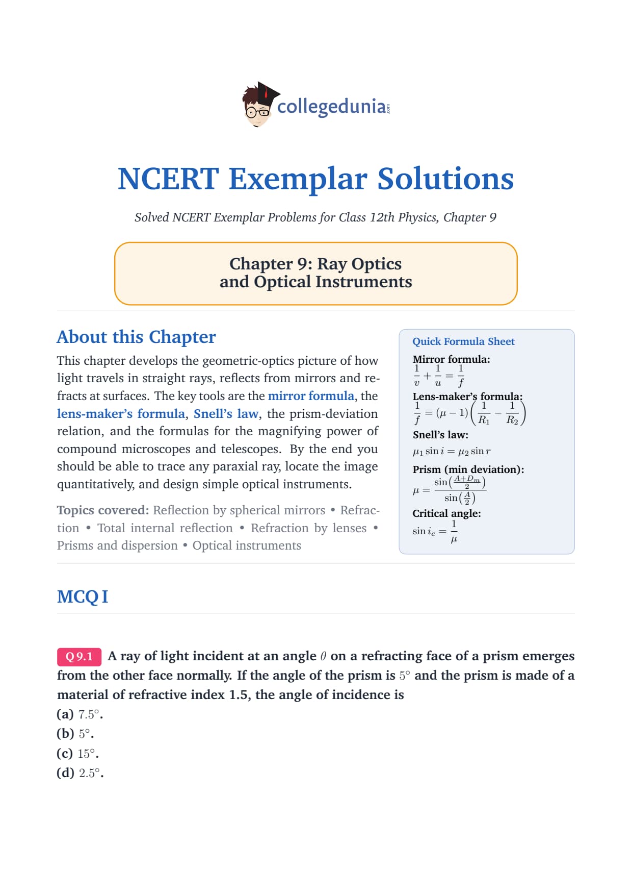
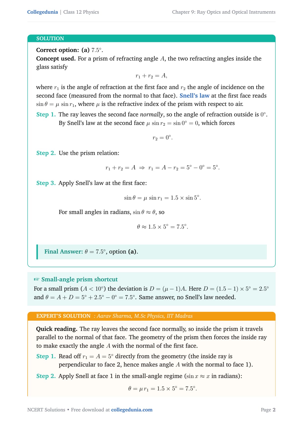
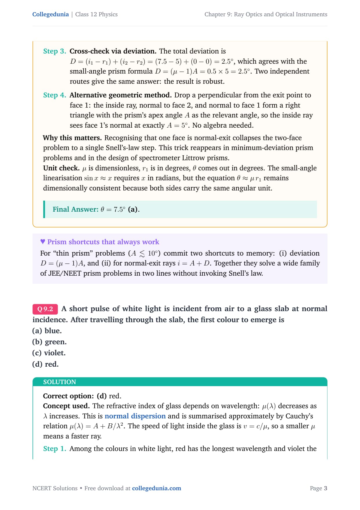
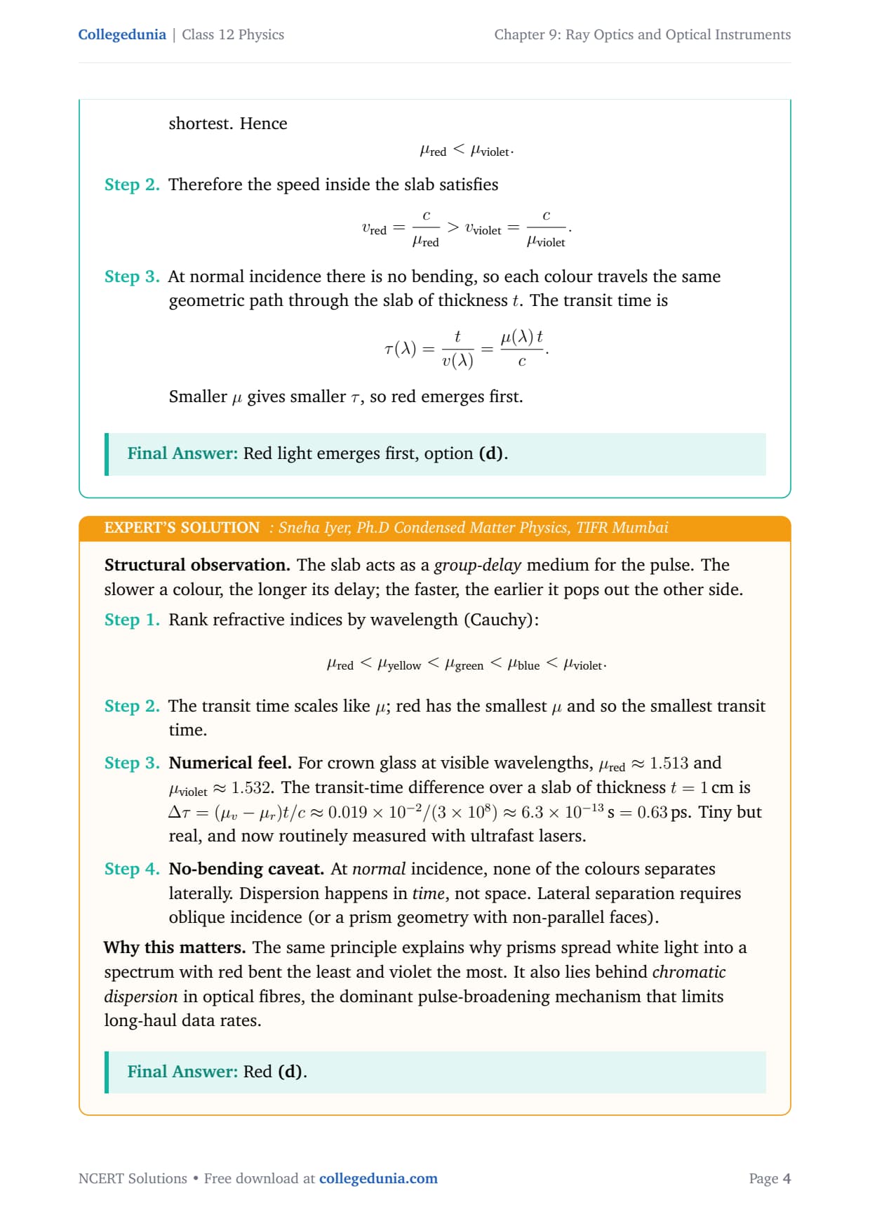

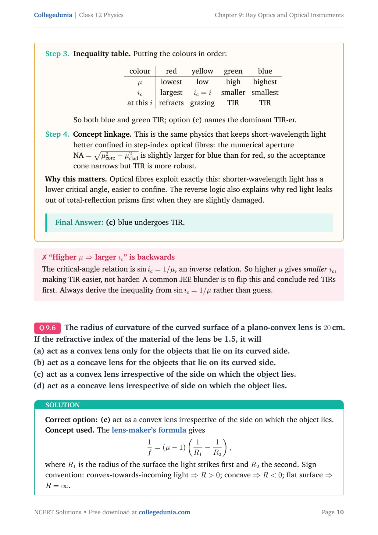
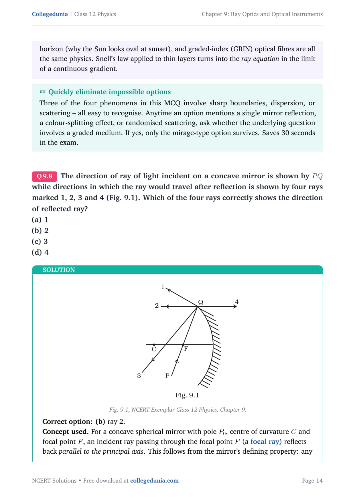
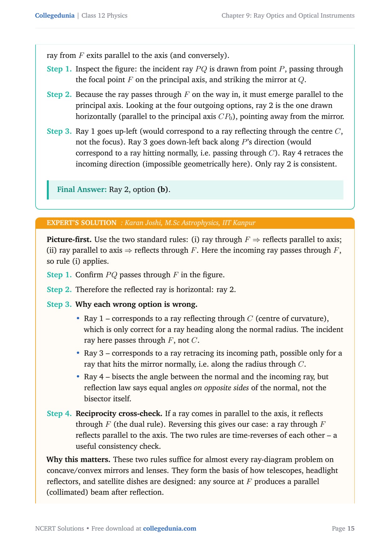
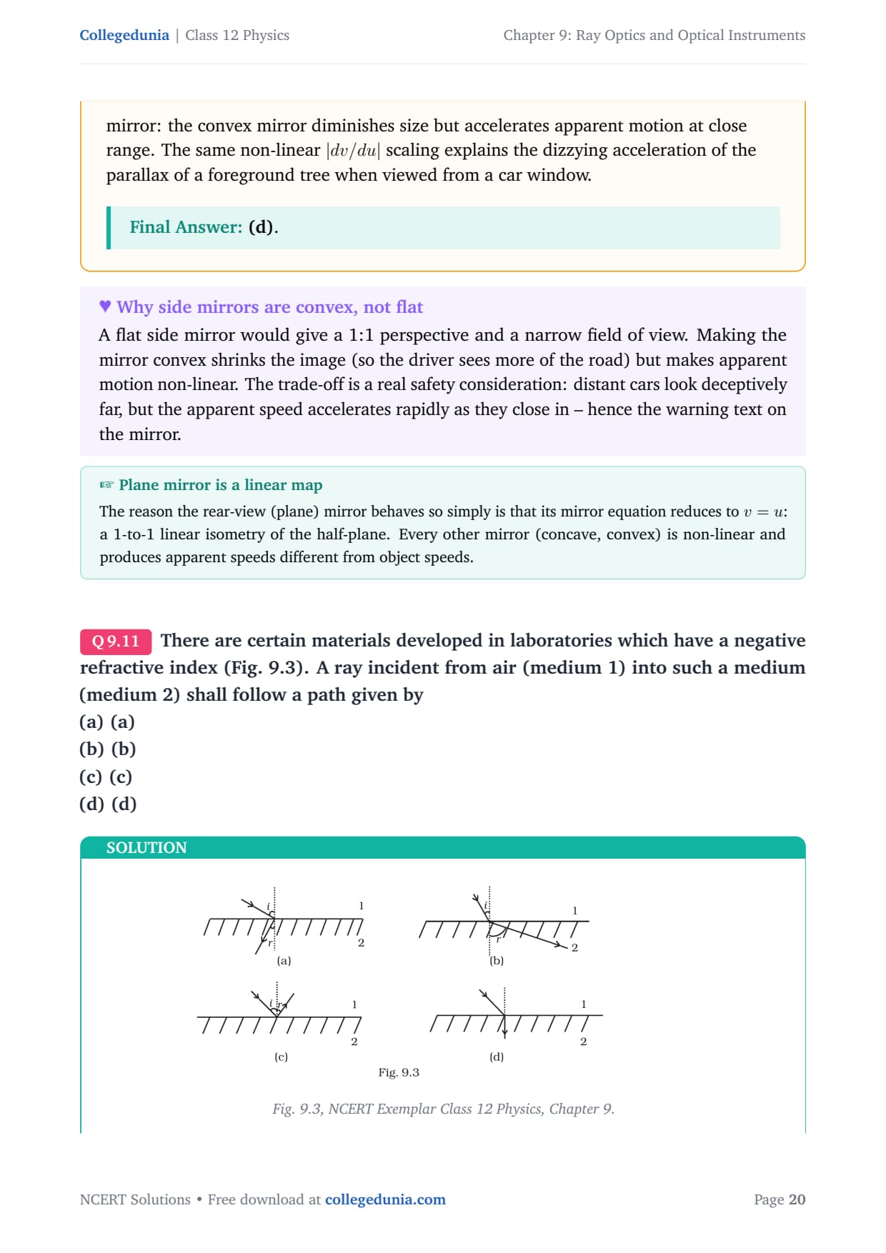
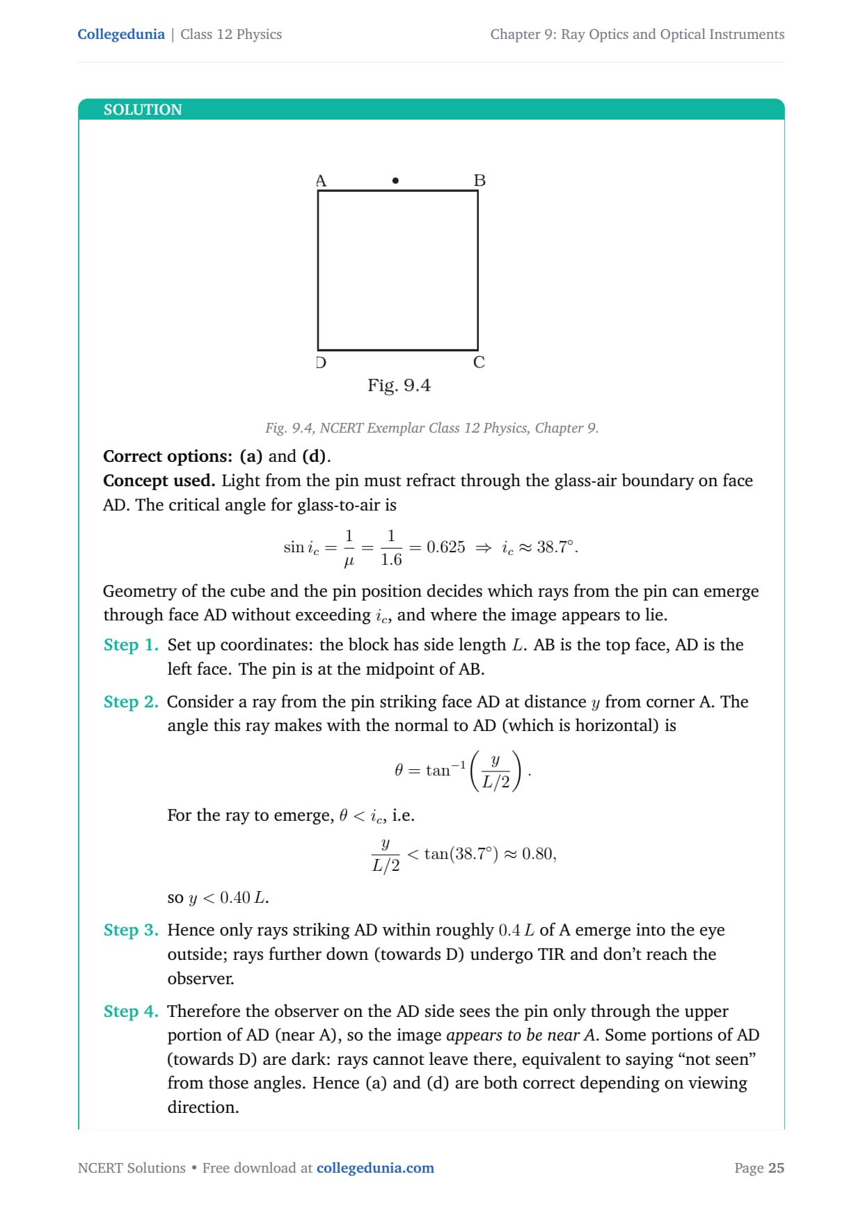
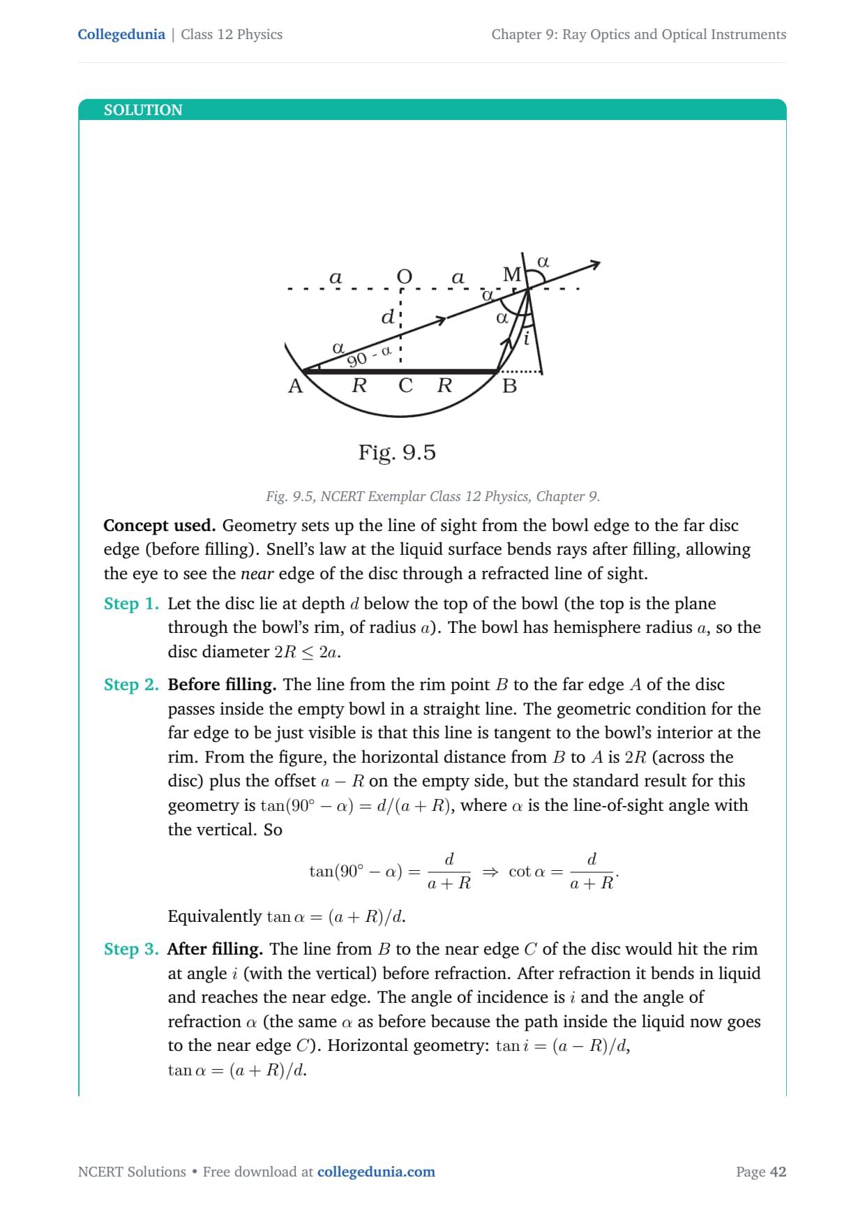
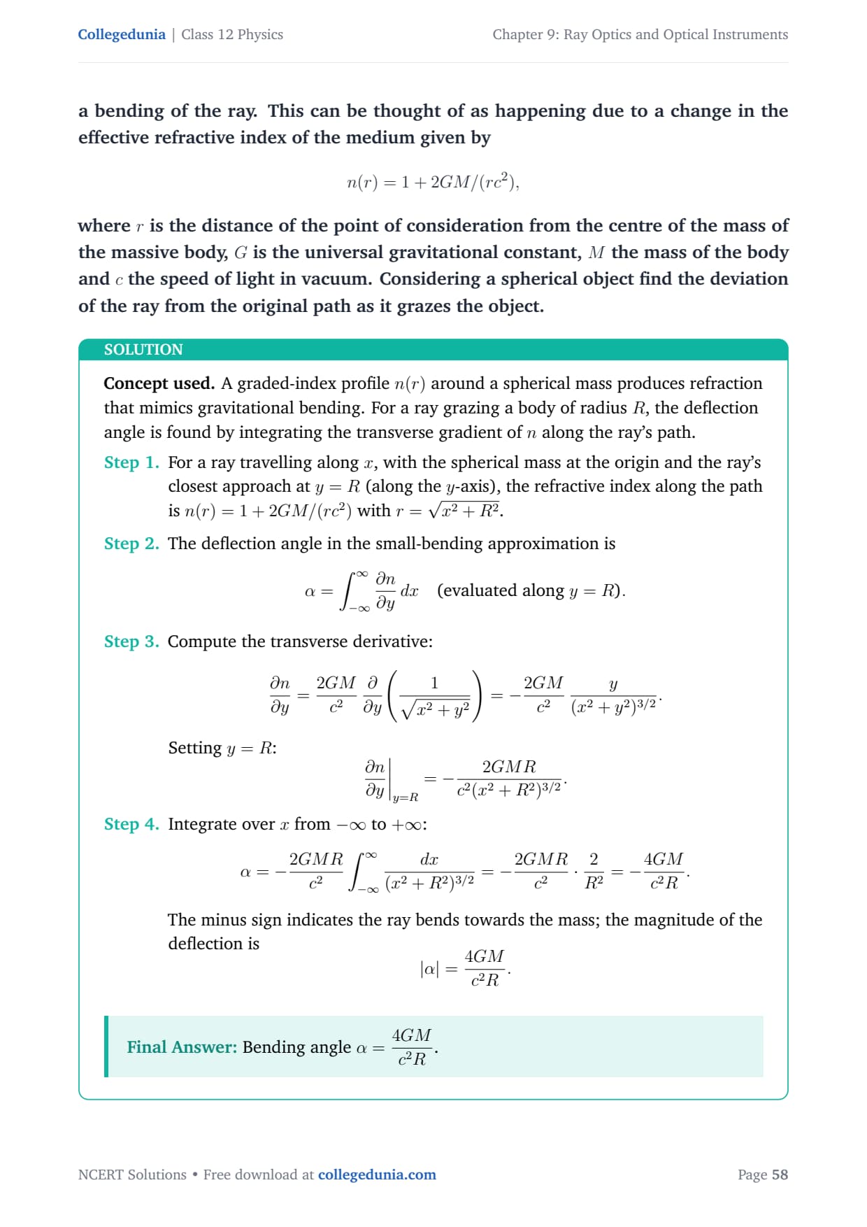
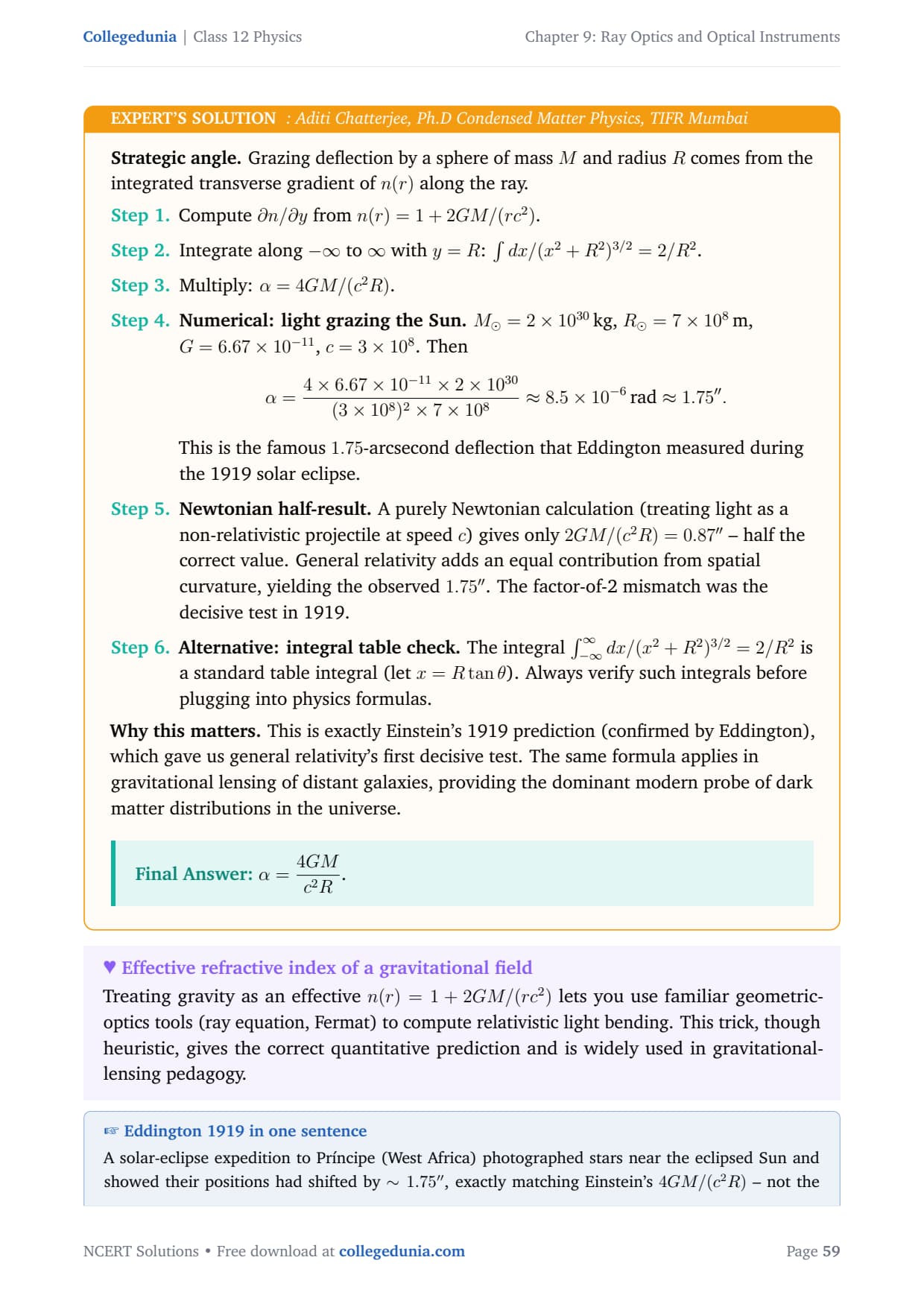
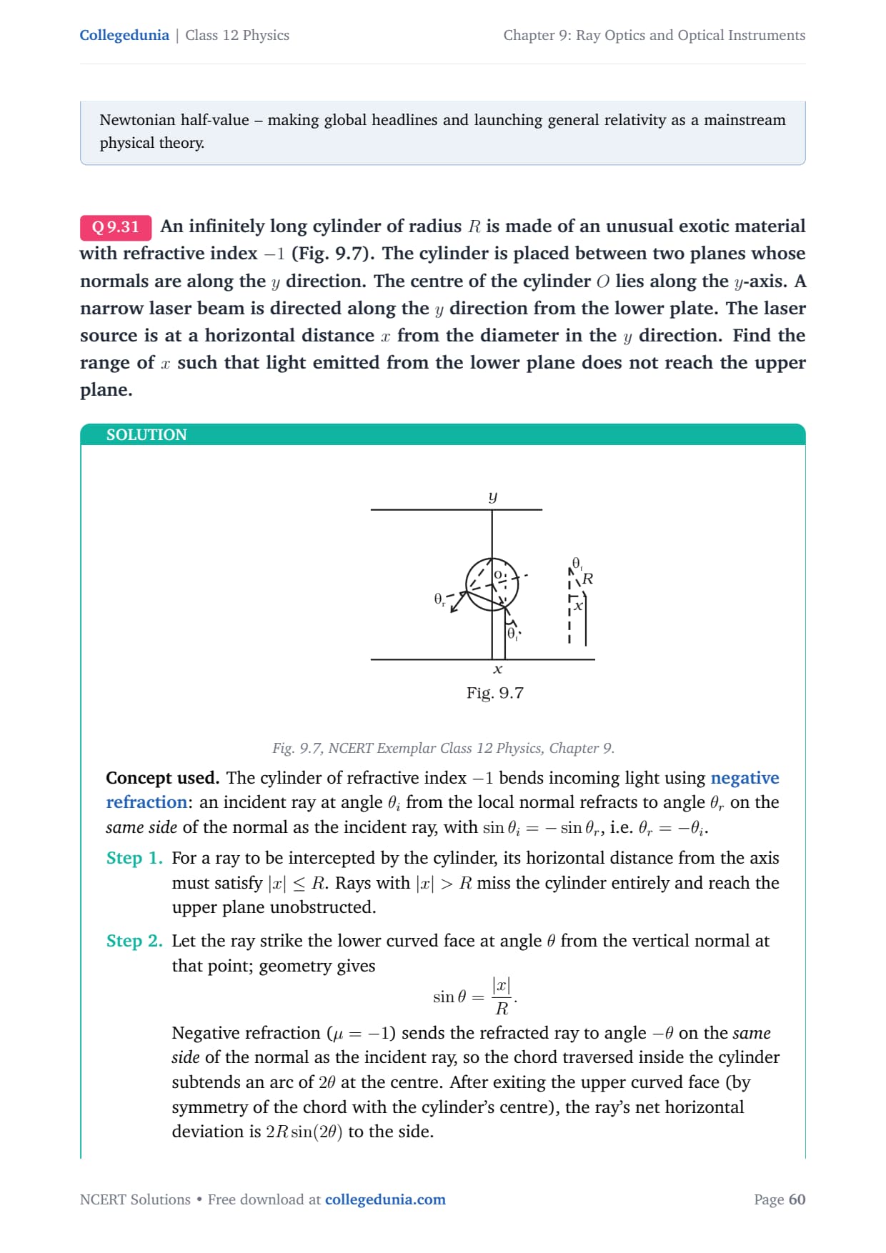
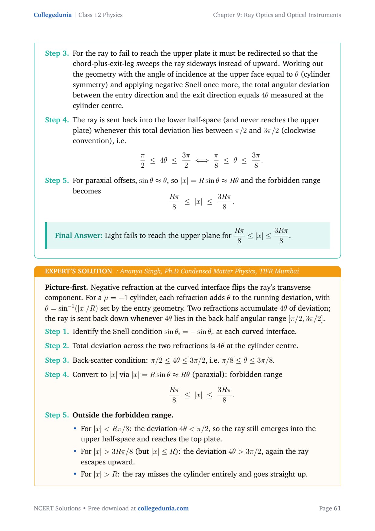
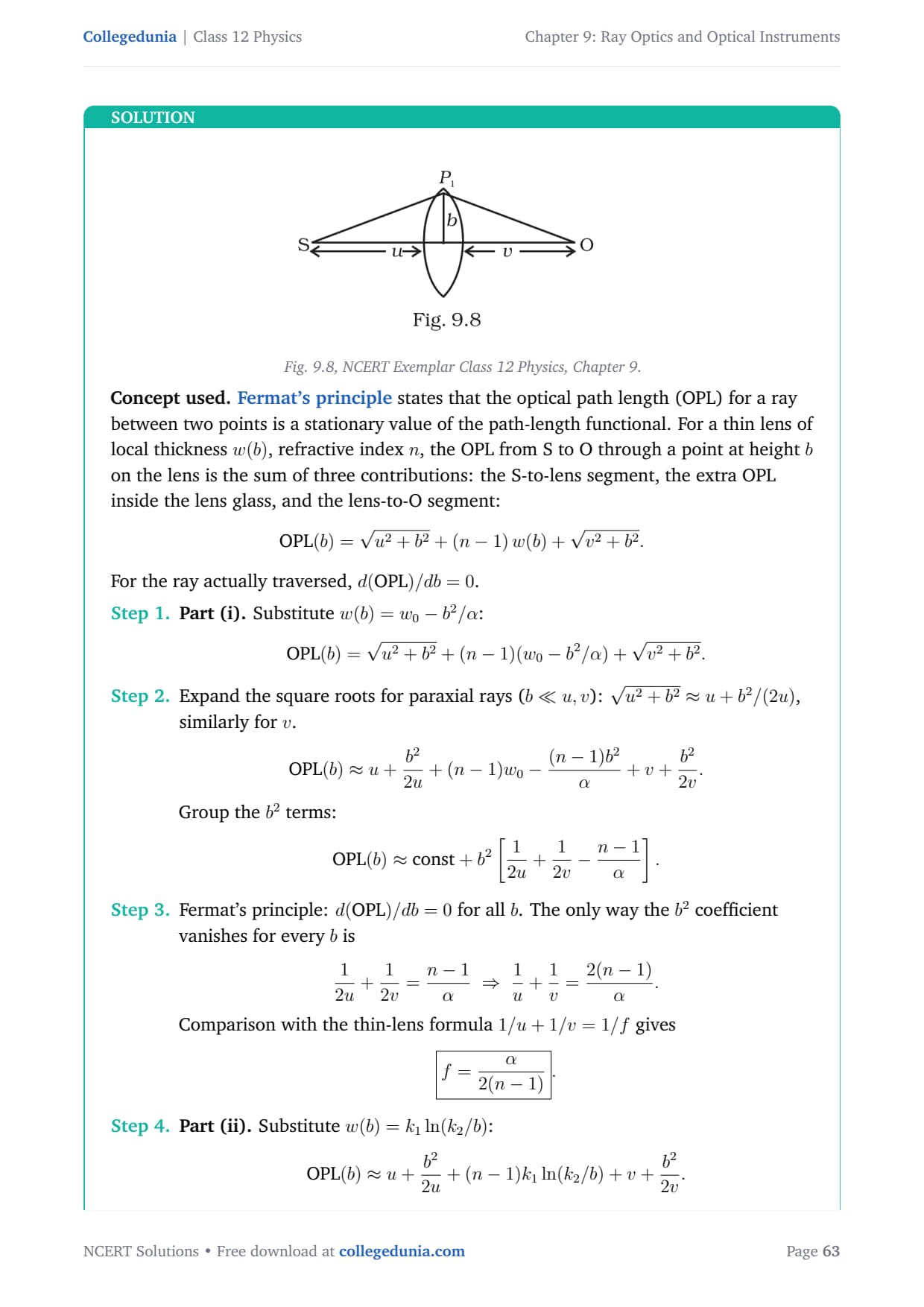

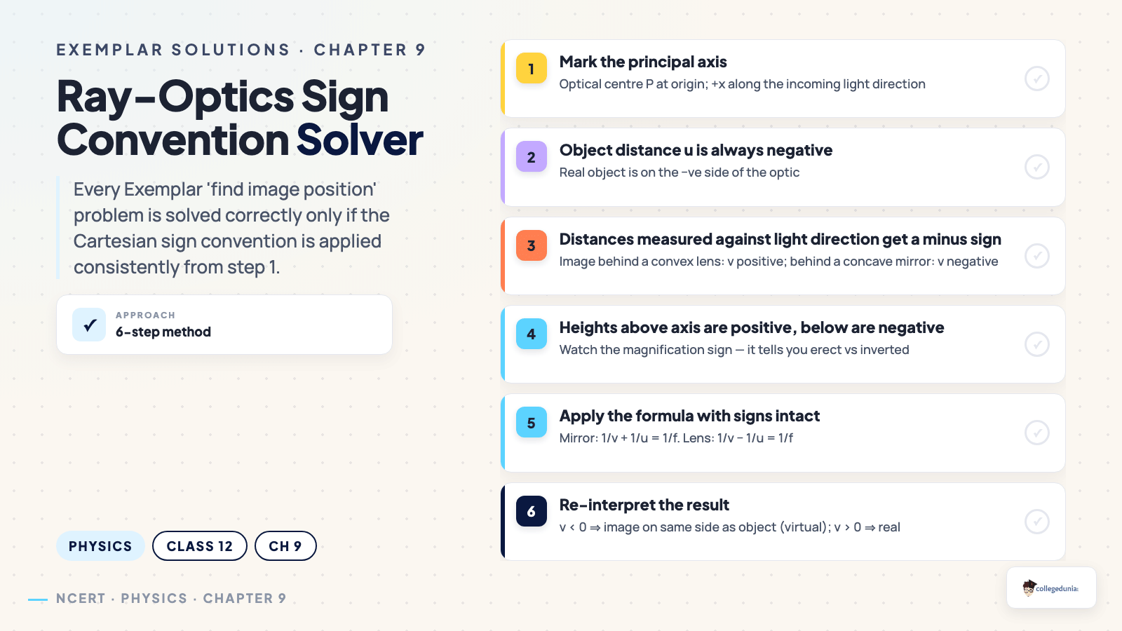
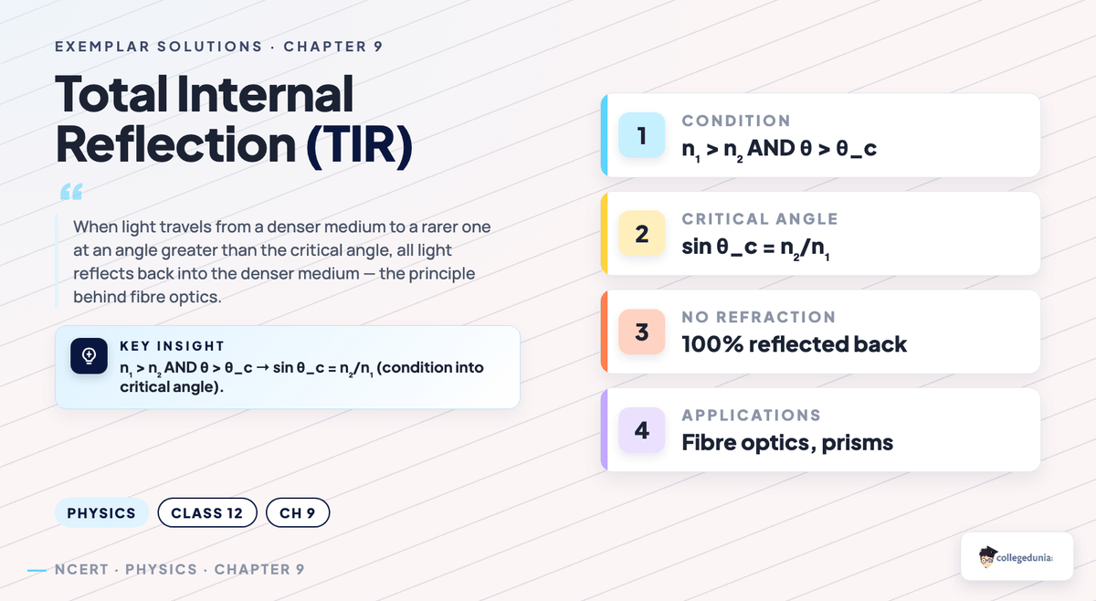
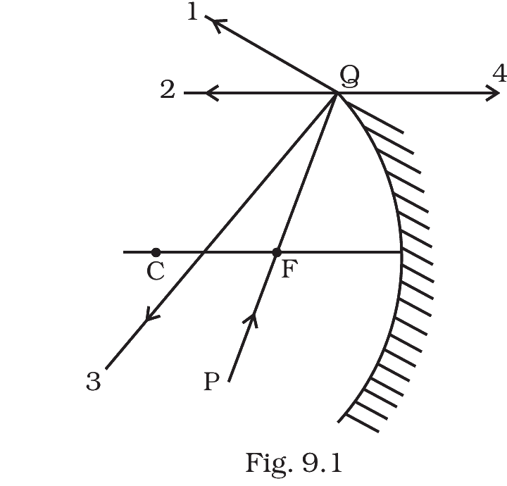
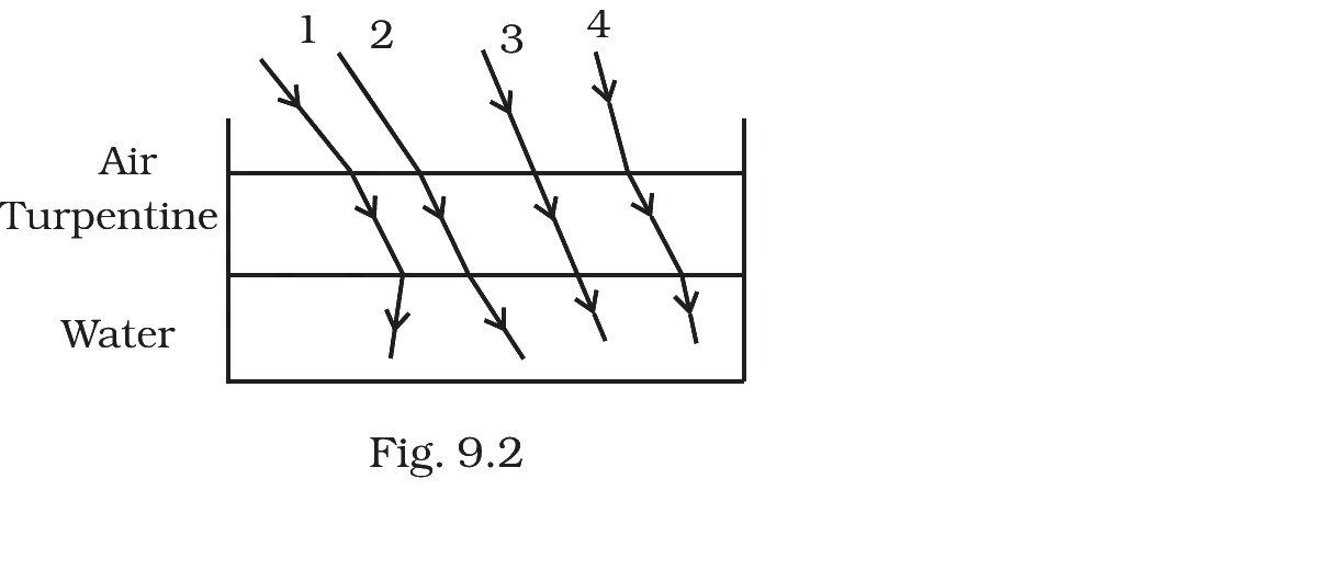
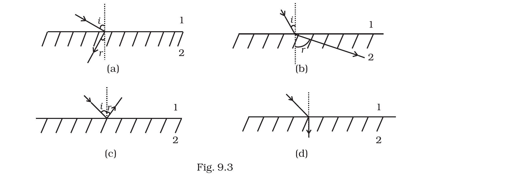
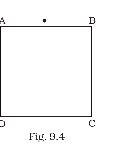
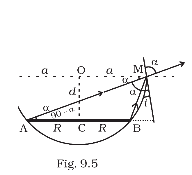
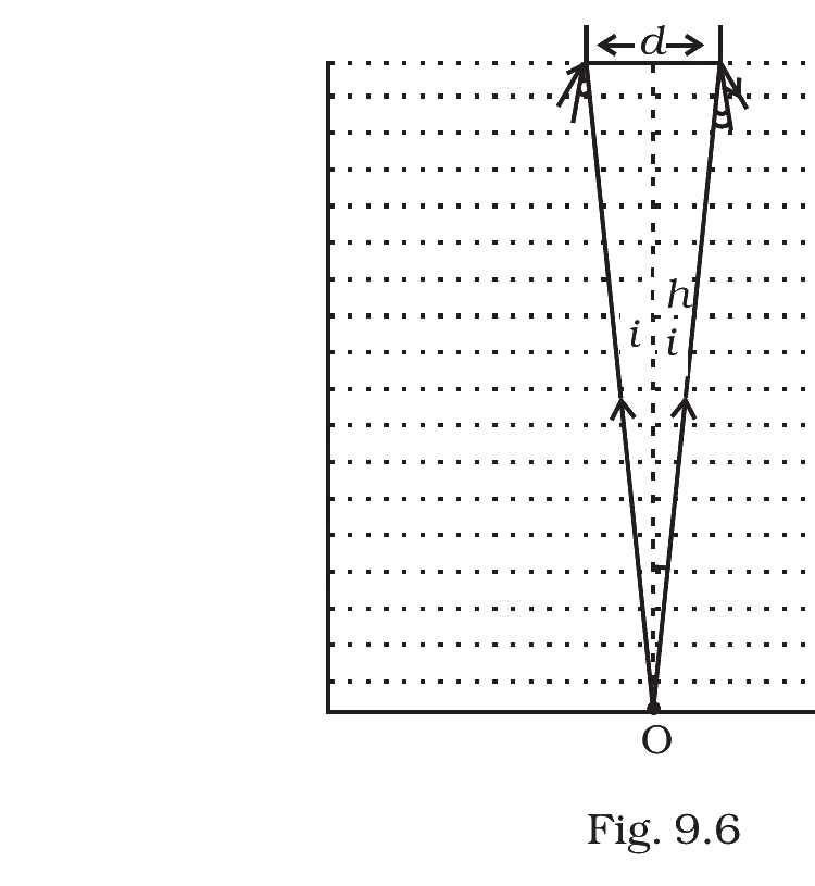
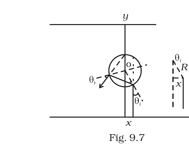
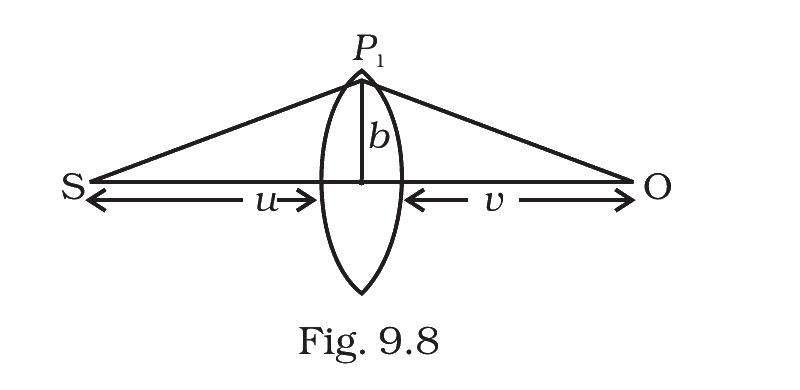



Comments