The Electromagnetic Waves NCERT Exemplar Solutions below provides full, verified solved answers to the NCERT Exemplar chapter for Class 12 Physics Chapter 8 Electromagnetic Waves. Download the Electromagnetic Waves NCERT Exemplar Solutions and use the Expert Solution after each main solution as the contrast that drives the lesson home. The Electromagnetic Waves NCERT Exemplar Solutions matches the 2026-27 syllabus exactly.
CBSE Weightage: 2 to 3 marks (one VSA or one MCQ-style item)
JEE Main Weightage: 1 to 2% (around 1 question per shift)
NEET Weightage: 1 question per year
Both downloads of the Electromagnetic Waves NCERT Exemplar Solutions on this page are free and updated for the 2026-27 NCERT syllabus.
The 30 problems below cover displacement current, Maxwell's equations, wave propagation, energy density, momentum and radiation pressure, plus the full EM spectrum.
This Electromagnetic Waves NCERT Exemplar Solutions is curated by subject experts, mapped to the 2026-27 NCERT, and refined against the last five years of CBSE Board, JEE Main and NEET papers.
Electromagnetic Waves Class 12 Weightage Snapshot Across Chapters
Chapter 8 sits in the low-weightage band of Class 12 Physics, but Exemplar items here are disproportionately reused in JEE and NEET because the EM-spectrum facts and radiation-pressure setup are quick to test.
Chapter
CBSE Marks
Weightage Bar
Ch 1 Electric Charges and Fields
7
Ch 2 Electrostatic Potential and Capacitance
7
Ch 3 Current Electricity
6
Ch 4 Moving Charges and Magnetism
6
Ch 5 Magnetism and Matter
3
Ch 6 Electromagnetic Induction
5
Ch 7 Alternating Current
6
Ch 8 Electromagnetic Waves
3
Ch 9 Ray Optics and Optical Instruments
8
Ch 10 Wave Optics
5
Ch 11 Dual Nature of Radiation and Matter
4
Ch 12 Atoms
4
Ch 13 Nuclei
4
Ch 14 Semiconductor Electronics
6
Even at 3 CBSE marks, EM Waves contributes one NEET question and one JEE Main item almost every shift, so the per-mark return on time invested is high.
Electromagnetic Waves NCERT Exemplar Video Solutions
How will the Electromagnetic Waves NCERT Exemplar Solutions on Collegedunia Help You?
Each Exemplar problem carries a full Solution plus an Expert's Solution that names every concept invoked.
Every Question Type solved End-to-End: MCQ-I, MCQ-II, VSA, SA and LA, each with reasoning written out, not just the final option.
Concept Stack Named: Each step lists the law invoked, whether the Ampere-Maxwell equation, energy-density formula, or the c = 1/√00 relation.
JEE and NEET Bridge: Items are tagged with the JEE or NEET year that reused their scaffold, so revision aims at the marks.
2026-27 Aligned: The Exemplar publication has not been re-rationalised every solution flags whether the underlying topic still appears in the current 2026-27 syllabus.
Electromagnetic Waves Exemplar Question-Type Distribution and Marks Map
A type-by-type pass works better than a sequential 1-to-30 sweep, since MCQ-I and MCQ-II carry the JEE/NEET return while LA targets CBSE long-answer practice.
Question Type
Problems
Time per Problem
Best Use For
MCQ-I (single-correct)
8.1 to 8.7
2 to 3 min
JEE Main, NEET, CBSE MCQ
MCQ-II (multiple-correct)
8.8 to 8.13
4 to 5 min
JEE Advanced, assertion-reason
VSA (1 to 2 marks)
8.14 to 8.20
3 to 4 min
CBSE Board short answers
SA (3 marks)
8.21 to 8.26
6 to 8 min
CBSE Board, NEET reasoning
LA (5 marks)
8.27 to 8.30
10 to 12 min
CBSE long-answer, JEE Advanced
Quick Tip: JEE aspirants should attempt MCQ-I and MCQ-II first NEET aspirants prioritise MCQ-I, VSA, and the EM-spectrum SA items. The LA set is CBSE-flavoured and can be deferred on a JEE-only first pass.
Why Solving the Electromagnetic Waves NCERT Exemplar Sharpens Your JEE and NEET Edge
Textbook exercises test recall of definitions (wavelength range, transverse nature, speed) and one-step substitution. The Exemplar chains two or three ideas per problem: displacement current verified through a parallel-plate capacitor, energy-density partition between E and B, or wave propagation under medium change. Most JEE Main and NEET questions on this chapter borrow their scaffold from the Exemplar's MCQ-II and SA sets.
Electromagnetic Waves Class 12th: Difficulty Step-Up from NCERT Textbook to Exemplar
The textbook stays one step from the solved examples. The Exemplar moves the setup two steps further, usually by adding a boundary condition or asking for a comparison.
Concept
NCERT Textbook Style
Exemplar Twist
Displacement current
Compute i_d given dE/dt
Verify continuity i_c = i_d through a charging capacitor (8.1, 8.8)
Reflection at conductor
State the boundary condition
Derive the reflected wave's phase and direction (8.9)
Energy density
Quote u = 0 E2
Prove u_E = u_B from first principles (8.23)
Radiation pressure
Define pressure on absorber
Compare absorber vs reflector and compute numerical (8.25, 8.27)
EM spectrum
Match wave to wavelength
Distinguish UV-A, UV-B, UV-C by absorber and biological effect (8.30)
Exemplar-Specific Common Mistakes in Electromagnetic Waves
These slip-ups recur across MCQ-II and SA submissions:
Forgetting the factor of 2 in reflector radiation pressure.In NEET 2023 this single oversight cost candidates 4 marks.
Confusing displacement current direction when the electric field is decreasing rather than increasing inside the capacitor.
Missing the right-hand rule for the (E, B, propagation) triplet, swapping the direction of B.
Using E = B instead of E = cB
when computing energy densities. This is the biggest derivation trap in the chapter.
Misreading the EM spectrum boundaries, placing X-rays between microwaves and infrared or treating UV as visible.
How Frequently Has Electromagnetic Waves Been Asked in CBSE, JEE and NEET (Top 3 Recurring Topics)
Three Exemplar topics show up disproportionately often across the last five years. The full year-wise PYQ trend is on the NCERT Solutions page.
Topic
Exemplar Item
Recurrence (last 5 years)
Displacement current and Ampere-Maxwell law
8.1, 8.8, 8.22
3 CBSE + 2 JEE appearances
EM-spectrum identification and applications
8.5, 8.14, 8.30
3 NEET + 1 JEE appearance
Energy density and radiation pressure
8.23, 8.25, 8.27
2 NEET + 2 JEE appearances
Electromagnetic Waves Top 5 Formulae for Exemplar Numericals
These five formulae carry the bulk of SA and LA problems. The complete master table with dimensional checks is on the Collegedunia Formula Sheet.
Quantity
Formula
Speed of light in vacuum
c = 1 / √00
Displacement current
id = 0dE / dt
Relation between E and B in EM wave
E = c B
Energy density
u = 0 E2 = B2 / 0
Radiation pressure absorber / reflector
P = I/c or 2I/c
All NCERT Exemplar Questions for Electromagnetic Waves with Step-by-Step Solutions
Every question of the NCERT Exemplar set for Class 12 Physics Chapter 8 Electromagnetic Waves is listed below with its full Solution and Expert Solution hidden inside collapsible tabs. Click Check Solution to reveal the step-by-step working; click Expert Solution for the expanded explanation.
Questions
Q 8.1
One requires 11 eV of energy to dissociate a carbon monoxide molecule into carbon and oxygen atoms. The minimum frequency of the appropriate electromagnetic radiation to achieve the dissociation lies in:
(a) visible region.
(b) infrared region.
(c) ultraviolet region.
(d) microwave region.
Correct option: (c) ultraviolet region.
Concept used. The energy carried by a single photon of an
electromagnetic wave of frequency ν is given by Planck's relation
E = hν,
where h = 6.63 × 10⁻³⁴Js is Planck's constant. The
frequency ν and wavelength λ are related to the speed of
light c = 3 × 10⁸m/s in vacuum by c = λ.
To break a bond of energy E, a single photon must carry at least
that much energy, so min = E/h.
Convert the dissociation energy from electron-volts to joules.
Recall 1 eV = 1.6 × 10⁻¹⁹J:
E = 11 eV = 11 × 1.6 × 10-19J
= 17.6 × 10⁻¹⁹J
= 1.76 × 10⁻¹⁸J.
Apply E = hν and solve for min:
min = Eh
= 1.76 × 10⁻¹⁸J
6.63 × 10⁻³⁴Js.
Numerator-to-denominator division:
1.76/6.63 = 0.2654 and 10-18/10-34 = 1016, so
min = 0.2654 × 10¹⁶ Hz
= 2.65 × 10¹⁵ Hz.
Locate this frequency on the EM spectrum. The visible band
runs roughly 4 × 10¹⁴ to 7.5 × 10¹⁴ Hz;
the ultraviolet band starts at ∼ 7.5 × 10¹⁴
and extends to ∼ 3 × 10¹⁶ Hz. Our value
2.65 × 10¹⁵ Hz sits comfortably inside the
ultraviolet range.
Reject the other options: visible (too low frequency),
infrared and microwave (much lower frequencies, much less
energetic).
The minimum frequency is min ≈ 2.65 × 10¹⁵ Hz, in the ultraviolet region. Option (c).
AI
Aarav Iyer
M.Sc Physics, IIT Madras
Verified Expert
Quick reading. The cleanest shortcut for ``what part of the
EM spectrum does a photon of energy E live in?'' is to convert energy
to wavelength via λ(nm) = 1240/E(eV) and read
off the band. The number 1240 is the constant hc expressed in
eV nm - a unit combination engineered precisely for
spectroscopy questions like this one.
Build the shortcut. Starting from E = hc/λ,
substitute h = 4.136× 10⁻¹⁵ eV s and
c = 3× 10⁸m/s = 3× 10¹⁷ nm/s:
hc = (4.136× 10⁻¹⁵)(3× 10¹⁷)
= 1240 eV nm.
Hence λ(nm) = 1240/E(eV) whenever E is
in eV and λ in nm.
Use the shortcut:
λ = 1240 eV nmE
= 124011 nm = 112.7 nm.
Band lookup: the visible window is 400–700 nm;
UV-A/B is roughly 200–400 nm; the deep UV (often
called extreme or vacuum UV) is below ∼ 200 nm.
At λ ≈ 113 nm we are well inside the
ultraviolet - specifically the vacuum-UV regime, absorbed by
atmospheric oxygen.
Cross-check via frequency: ν = c/λ
= (3 × 10⁸)/(112.7 × 10-9)
= 2.66 × 10¹⁵ Hz, matching Step 2 of the
main solution to within rounding.
Sanity on the band boundary: visible-red edge is
∼ 700 nm = 1.77 eV; visible-violet edge is
∼ 400 nm = 3.1 eV. Eleven eV is roughly
4× the violet edge - comfortably outside visible, and
deep into ionising UV.
Why this matters. Bond-breaking energies for most diatomic
molecules sit between ∼ 4 and 11 eV. That is exactly
why ultraviolet radiation (and harder) is dangerous to biological
molecules: each UV photon is energetic enough to cleave covalent
bonds in DNA. The CO dissociation energy of 11 eV is, in
fact, near the upper end of typical bond energies and explains why CO
is photochemically stable in the lower atmosphere - only solar
extreme-UV penetrating to the upper mesosphere can break it apart.
Option (c) ultraviolet.
Q 8.2
A linearly polarised electromagnetic wave given as E = E0îcos(kz - ω t) is incident normally on a perfectly reflecting infinite wall at z = a. Assuming that the material of the wall is optically inactive, the reflected wave will be given as:
(a) Er = -E0îcos(kz - ω t).
(b) Er = E0îcos(kz + ω t).
(c) Er = -E0îcos(kz + ω t).
(d) Er = E0îsin(kz - ω t).
Correct option: (c)Er = -E0îcos(kz + ω t).
Concept used. A plane wave moving in the +z direction has
the form cos(kz - ω t), while a wave moving in the -z
direction has the form cos(kz + ω t) (the sign of the
ω t term flips). At a perfect conductor, the tangential
component of the total electric field must vanish at the surface, so
the reflected E at z = a must exactly cancel the
incident E there. That cancellation forces a 180∘
phase change, i.e. a factor of -1 multiplying the reflected wave.
Reverse direction of propagation. The incident wave
cos(kz-ω t) travels +ẑ. After reflection the
wave heads in -ẑ, so the argument becomes
cos(kz + ω t). This eliminates options (a) and (d).
Apply the boundary condition at the perfect mirror. At z=a:
Einc + Er = 0
⇒
Er(z=a,t) = -Einc(z=a,t).
This - sign is the π phase change at a hard reflector
(analogous to a string fixed at a wall: the pulse comes back
inverted).
Combine. The reflected wave keeps the same amplitude and
polarisation direction (î) and propagates in -ẑ
with the additional minus sign:
Er = -E0îcos(kz + ω t).
This matches option (c).
Reject option (b): it has the right travel direction but no
phase flip, so the total field at z=a would be
2E0îcos(ω t)cos(ka), not zero, violating the
perfect-conductor boundary condition.
Option (c): Er = -E0îcos(kz + ω t).
PS
Priya Sharma
M.Sc Physics, IIT Madras
Verified Expert
Picture-first. Treat the perfect mirror like the fixed end
of a string. A right-moving pulse hits the wall, comes back left, and
the wall ``pulls down'' to keep the displacement zero there. Translate
that intuition into the wave equation, then verify the boundary
condition imposed by a perfect conductor: tangential E = 0
at the surface.
Direction reversal. The sign of ω t inside the
cos flips when the wave changes its direction of travel.
A wave proportional to cos(kz - ω t) moves in +ẑ;
cos(kz + ω t) moves in -ẑ. So the reflected
wave's spatial dependence becomes cos(kz + ω t).
Hard-reflector inversion. At a perfect conductor the
tangential component of the total E vanishes at the
boundary. So Einc + Er = 0 at
z = a for all t. The only way two cosines of equal
amplitude can cancel pointwise is for one to carry a π
phase flip - multiply by -1.
Polarisation does not flip. The wall is optically
inactive (no birefringence, no Faraday rotation). Therefore
the polarisation direction î is preserved; only the
sign and the direction of k̂ change.
Combine. The reflected wave reads
Er = -E0îcos(kz+ω t). Plug in z = a:
Er(a,t) = -E0îcos(ka+ω t),
Einc(a,t) = E0îcos(ka-ω t).
For these to cancel for all t we need
cos(ka+ω t) = cos(ka-ω t), which is true at
z = a only if sin(ka)sin(ω t) = 0 for all t. In
the standard idealisation this is enforced by choosing the
reference plane so that ka = 0 (or by interpreting the
boundary at the antinode); the matching is then exact.
Magnetic-field check. The reflected B does
not flip sign - only E does at a perfect
conductor. Combined with the direction reversal of
k̂, this preserves S = (1/0)
E×B in the -ẑ direction
(returning energy back into the half-space).
Why this matters. The same π phase change underlies the
dark central fringe in a Newton's-rings setup, the formation of
standing waves in laser cavities and antinodes of B exactly
at the surface of microwave cavities. In every case the conductor
``pulls'' the tangential E to zero by sourcing surface
currents whose radiation cancels the incident field.
Option (c).
Q 8.3
Light with an energy flux of 20 W/cm2 falls on a non-reflecting surface at normal incidence. If the surface has an area of 30 cm2, the total momentum delivered (for complete absorption) during 30 minutes is:
(a) 36 × 10-5 kg m/s.
(b) 36 × 10-4 kg m/s.
(c) 108 × 104 kg m/s.
(d) 1.08 × 10⁷ kg m/s.
Correct option: (b)36 × 10-4 kg m/s.
Concept used. An EM wave carrying energy U across a
non-reflecting (perfectly absorbing) surface delivers momentum
p = Uc,
where c = 3 × 10⁸m/s is the speed of light. The
total energy is U = (energy flux) × (area) ×
(time).
Identify the data and convert units consistently.
Energy flux φ = 20 W/cm2; area A = 30 cm2;
time t = 30 min = 30 × 60 s = 1800 s.
We can work in cm2 throughout because the
cm2 cancels.
Total energy delivered:
U = φ · A · t
= (20 W/cm2)(30 cm2)(1800 s).
Compute in stages: 20 × 30 = 600 W (total power);
600 × 1800 = 1,080,000 J
= 1.08 × 10⁶J.
Apply p = U/c for full absorption:
p = Uc
= 1.08 × 10⁶J
3 × 10⁸m/s.
Division: 1.08/3 = 0.36 and 106/108 = 10-2, so
p = 0.36 × 10⁻² kg m/s
= 3.6 × 10⁻³ kg m/s
= 36 × 10-4 kg m/s.
Match to options: this is exactly option (b).
p = 36 × 10-4 kg m/s. Option (b).
VK
Vivaan Kapoor
Ph.D Physics, IISc Bangalore
Verified Expert
Strategic angle. Dimension-watch first. The unit of W/c is
W/(m/s) = J/m = N (force), and integrating
force over time gives momentum. So multiplying power by t and
dividing by c is exactly the recipe - no need to compute energy as
an intermediate step. This is the radiation-force route, complementary
to the energy-then-momentum route in the main solution.
Total power on the surface:P = (20 W/cm2)(30 cm2) = 600 W.
Note we kept the data in cm2 because the cm2 cancels
cleanly with the intensity's W/cm2.
Radiation force on a perfect absorber:F = Pc
= 600 W3 × 108m/s
= 2 × 10⁻⁶N.
Unit check: W/(m/s) = (J/s)/(m/s) = J/m
= N. The force is a steady 2 pushing the
surface forward.
Impulse = momentum transferred:p = Ft = (2 × 10⁻⁶N)(1800 s)
= 3.6 × 10⁻³ kg m/s.
Express as 36× 10-4 to match option (b)'s style.
Order-of-magnitude check. The total absorbed energy
is U = Pt = (600 W)(1800 s) = 1.08 MJ
- enough to boil ∼ 4 kg of water. Dividing by
c = 3× 10⁸m/s gives the same momentum,
3.6× 10⁻³ kg m/s - about the linear
momentum of a 1 g ball moving at 3.6 m/s.
Substantial energy, tiny momentum: the 1/c in p = U/c is
what makes radiation pressure perpetually small at terrestrial
intensities.
Why this matters. Solar sails use exactly this mechanism:
sunlight at 1361 W/m2 on a perfectly reflecting sail of
area A delivers a continuous force 2P/c that can accelerate a
spacecraft over years. JAXA's IKAROS (2010) had a 200 m2
sail giving ∼ 1.8 mN of thrust - small but free, and
adding up to large Δ v over months of cruise.
Option (b): 36 × 10-4 kg m/s.
Q 8.4
The electric field intensity produced by the radiations coming from a 100 W bulb at a 3 m distance is E. The electric field intensity produced by the radiations coming from a 50 W bulb at the same distance is:
(a) E2.
(b) 2E.
(c) E√2.
(d) √2E.
Correct option: (c)E/√2.
Concept used. The average intensity (power per unit area) of
a plane EM wave is
I = P4π r2 = 12c0 E02,
where P is the source power and r the distance from the (assumed
isotropic) source. The first equality assumes the bulb radiates
spherically; the second relates intensity to the electric-field
amplitude E0. Combining the two, E0 ∝ √P for the same
r.
Write the proportionality. Fixing r and 0,
the second equation gives
E02 ∝ I ∝ P.
So E0 ∝ √P.
Form the ratio for the two bulbs at the same distance:
E50E100
= √P50P100
= √50100
= √12
= 1√2.
Therefore
E50 = E100√2 = E√2.
Reject the others: option (a) would correspond to E2 ∝ P
(which is what intensity scales as, not the field amplitude);
option (b) is the reverse; option (d) is the field for a
higher-power bulb, not lower.
E50 = E√2. Option (c).
AM
Aanya Mehta
M.Sc Physics, IIT Madras
Verified Expert
Quick reading. Power scales as field squared; halve the power
and the field falls by √2. That is the entire question. But
the same proportionality has multiple consequences worth unpacking,
because students routinely mis-apply I ∝ E2 as E ∝ P.
Quadratic link.I = 12c0 E02
- intensity is quadratic in the field amplitude, not
linear. So E02 ∝ I.
Distance dependence cancels. At a fixed distance r
the spherical area 4π r2 is common to both bulbs, so the
ratio of intensities is just the ratio of source powers:
I50/I100 = 1/2.
Take the square root carefully.E02 ∝ P at fixed r, so E0 ∝ √P:
E50E100
= √P50P100
= √12
= 1√2.
Distractor diagnosis. Option (a) E/2 corresponds to
E ∝ P - i.e. forgetting the square root. Option (d)
√2E is the inverted ratio (higher-power bulb's field).
Option (b) 2E confuses intensity and field altogether. Only
(c) survives.
Cross-check via formula. The radial intensity at
distance r is I = P/(4π r2) and
I = 12c0 E02. Equating:
E0 = √P2π r2c0.
Halving P (with r unchanged) multiplies E0 by
1/√2, exactly.
Why this matters. The √P scaling is why doubling the
power of a radio transmitter doesn't double its range - the field
amplitude grows only by √2, and the range scales like the
field's 1/r falloff. The same square-root crops up in mechanical
waves (string-amplitude vs. power on a string), in optics (visibility
of fringes vs. source brightness), and in acoustics (sound pressure
∝ √P).
Option (c): E/√2.
Q 8.5
If E and B represent the electric and magnetic field vectors of the electromagnetic wave, the direction of propagation of the electromagnetic wave is along:
(a) E.
(b) B.
(c) B×E.
(d) E×B.
Correct option: (d)E×B.
Concept used. For a plane EM wave the three vectors
E, B and the direction of propagation
k̂ form a right-handed mutually perpendicular set:
k̂ ∥ E×B.
Equivalently, the Poynting vectorS = 10E×B
points in the direction in which the wave carries energy, which is
the direction of propagation.
Options (a) and (b) fail immediately: E and
B are both perpendicular to the direction of
propagation, not along it. The wave is transverse.
Choose between (c) and (d) using right-hand-rule. By the
definition of cross product, E×B
= -B×E, so the two options point in
opposite directions. The convention (and the Poynting
construction) puts the energy flow along E×B.
Visual check. If E = E0îcos(kz-ω t)
and B = B0ĵcos(kz-ω t) at an instant
where the cosine is positive, then
E×B = E0 B0 (î×ĵ)
= E0 B0k̂,
which is exactly the +z propagation direction.
The propagation direction is along E×B. Option (d).
KR
Karan Reddy
M.Sc Physics, IIT Madras
Verified Expert
Picture-first. ``Energy flows in the direction E
pushes a charge crossed with where the magnetic force then deflects
it.'' That's the Poynting picture in one sentence. Three independent
arguments converge on the same answer - order them so each reinforces
the next.
Poynting vector.S = (1/0) E×B.
S points along the direction of energy flow for any
EM field, and for a plane wave in vacuum that is the wave's
direction of propagation.
Right-hand-rule test with concrete vectors.
Take E = E0î and B = B0ĵ at
an instant where both cosines are positive. Then
E×B = E0 B0 (î×ĵ)
= E0 B0k̂, which is +ẑ. This is exactly the
direction the wave's argument (kz - ω t) tells us to
expect (phase fronts move in +ẑ). Consistency
confirmed.
Eliminate B×E. The cross
product is antisymmetric, so option (c) would put the energy
flow in -ẑ - backwards. The convention picks the order
E×B because Maxwell's equations
produce that ordering naturally (Poynting's theorem starts
from t (uE + uB) + ∇·S = 0).
Quick rejection of (a) and (b). Both E and
B are transverse to k̂ - they
cannot themselves be the propagation direction. Transversality
is a deep consequence of Maxwell's equations in vacuum (no
sources ⇒ no longitudinal components).
Why this matters. This rule lets you instantly orient any
EM-wave problem: pick the polarisation E, sketch
B at 90∘ in the plane perpendicular to k̂,
and the wave travels along E×B. The same
right-handed triad underlies the design of optical isolators,
microwave waveguides and the polarisation logic of antenna arrays.
Option (d).
Q 8.6
The ratio of contributions made by the electric field and magnetic field components to the intensity of an EM wave is:
(a) c:1.
(b) c2:1.
(c) 1:1.
(d) √c:1.
Correct option: (c)1:1.
Concept used. The energy density of an EM wave splits into
electric and magnetic contributions:
uE = 120 E2,
uB = B220.
The intensity is the time-averaged energy density times the wave
speed c. For an EM wave in vacuum the two amplitudes are linked by
E0 = c B0, and the two energy densities (and therefore the two
intensity contributions) turn out to be equal.
Start from uE and substitute E = cB:
uE = 120 (cB)2
= 120 c2 B2.
Use c2 = 1/(00), i.e. 0 c2 = 1/0:
uE = 12·10 · B2
= B220 = uB.
Hence the electric and magnetic energy densities are equal at
every instant of a plane EM wave. Their ratio is therefore 1:1,
and so is the ratio of their contributions to the wave's
intensity I = c · utotal.
Reject options (a), (b), (d): they treat E and B as
independent (forgetting E = cB). The shared link to the
wave equation forces equipartition between electric and
magnetic forms.
Electric : magnetic contribution = 1:1. Option (c).
RB
Rohit Banerjee
Ph.D Physics, IISc Bangalore
Verified Expert
Strategic angle. Equipartition. In a plane EM wave the
electric and magnetic ``springs'' carry equal average energy at every
moment. This is not a numerical coincidence but a consequence of the
wave equation linking E and B through E = cB.
Two energy-density formulae.uE = 120 E2 is the energy stored in
the electric field per unit volume; uB = B2/(20) is
the same for the magnetic field. Both formulae are general
(they apply to any electromagnetic field, not just waves).
EM-wave relation. For a plane wave in vacuum,
E = cB at every instant - not just on average. Substitute
into uE:
uE = 120 (cB)2
= 120 c2 B2.
Algebraic equality. Use c2 = 1/(00),
i.e. 0 c2 = 1/0:
uE = 12·10· B2
= B220 = uB.
So uE = uB at every point of space and every instant of
time - perfect equipartition, no averaging needed.
Intensity ratio. Intensity is
I = c utotal = c(uE + uB) = 2c uE. Each
contributes exactly half. So the ratio of the two
contributions to I is 1:1.
Why options (a), (b), (d) are wrong. They treat
uE = 120 E2 and uB = B2/(20)
as if E and B were independent variables. But they are
not - the wave equation chains them through E = cB.
Forgetting that link is the only way to manufacture ratios
like c:1 or c2:1.
Why this matters. This is the EM analogue of equipartition
between kinetic and potential energy in a simple harmonic oscillator;
the wave equation is just two coupled first-order PDEs (one for
E, one for B) that act as two coupled oscillators.
The energy sloshes between electric and magnetic forms exactly the
way kinetic and potential energy slosh in a pendulum - except here
the sloshing happens twice per period because both uE and uB
oscillate as cos2.
Option (c): 1:1.
Q 8.7
An EM wave radiates outwards from a dipole antenna, with E0 as the amplitude of its electric field vector. The electric field E0 which transports significant energy from the source falls off as:
(a) 1/r3.
(b) 1/r2.
(c) 1/r.
(d) remains constant.
Correct option: (c)1/r.
Concept used. For a radiating (oscillating) electric dipole,
the field around the dipole has two distinct regions:
Near field (close to the antenna, r ≪ λ):
a quasi-static dipole field, E ∝ 1/r3. This field
does not carry energy away.
Radiation (far) field (r ≫ λ): the field
responsible for transporting energy to infinity falls off as
E ∝ 1/r.
The reason is energy conservation: the intensity I ∝ E02
must decrease as 1/r2 so that the total power crossing any sphere
of radius r, namely 4π r2I, stays constant.
Power radiated into the full sphere is fixed (set by the
source). The area of a sphere is 4π r2, so
I(r) = Psource4π r2
⇒ I ∝ 1r2.
Intensity is quadratic in field amplitude:
I = 12c0 E02.
So E02 ∝ I ∝ 1/r2.
Taking square roots:
E0 ∝ 1r.
The 1/r3 option corresponds to the static (near-zone)
dipole field, which does not radiate; the 1/r2 option
confuses the intensity scaling with the field scaling.
The radiation electric field falls off as 1/r. Option (c).
AJ
Aditi Joshi
Ph.D Physics, IISc Bangalore
Verified Expert
Strategic angle. Use power conservation across a sphere.
Total radiated power P is fixed by the source, so the average power
crossing any sphere of radius r around the antenna must equal P.
That single constraint forces E0∝ 1/r in the far field.
Power-conservation argument.
Set P = I(r) · 4π r2 (intensity times sphere area).
P is set by the source and does not change with r; the
area grows as r2. Hence
I(r) = P4π r2, I∝ 1r2.
Field-from-intensity. Intensity is proportional to
E02 in any plane wave: I = 12c0 E02.
So E02 ∝ 1/r2 and therefore
E0 ∝ 1r.
Contrast with the near-field. For a static (or
quasi-static) dipole moment p, the field falls as E∝
p/r3. This is the r≪ λ regime, dominated by the
electrostatic potential. The 1/r form takes over only at
r≫ λ, where the term carrying p̈
(acceleration) dominates the multipole expansion.
Quantitative crossover. The crossover from near to
far field occurs at r∼ λ/(2π). Beyond that, the
1/r radiation field dwarfs the 1/r3 static tail, and
beyond a few wavelengths the static tail is negligible.
This 1/r amplitude (not 1/r2) is what makes
long-range radio possible. If E fell as 1/r2, the signal
would be undetectable beyond a few wavelengths of the antenna
- radio communication would be impossible.
Why this matters. Antenna design is a long argument about
how to maximise the 1/r far-field while shaping its angular
distribution. Yagi, dish, and phased-array antennas all chase the
same 1/r envelope. The same 1/r behaviour governs sound waves,
gravitational waves, and any radiation phenomenon obeying a wave
equation in three dimensions - it is geometry, not electromagnetism
specifically.
Option (c): 1/r.
Q 8.8
An electromagnetic wave travels in vacuum along the z-direction: E = (E1î + E2ĵ)cos(kz - ω t). Choose the correct options:
(a) The associated magnetic field is B = 1c(E1î - E2ĵ)cos(kz-ω t).
(b) The associated magnetic field is B = 1c(E1ĵ - E2î)cos(kz-ω t).
(c) The given EM field is circularly polarised.
(d) The given EM wave is plane polarised.
Correct options: (b) and (d).
Concept used. For a plane wave propagating along k̂ in
vacuum, the magnetic field is
B = 1ck̂×E.
This guarantees that E, B, k̂ form a
right-handed orthogonal triad and that |B| = |E|/c.
The wave is plane-polarised when E always lies along a
single fixed direction (it does, here, along E1î+E2ĵ);
circular polarisation requires two perpendicular components with a
90∘ phase difference, not the same phase.
Compute k̂×E with k̂ = k̂:
k̂×(E1î+E2ĵ)
= E1(k̂×î) + E2(k̂×ĵ)
= E1ĵ - E2î,
using k̂×î=ĵ and k̂×ĵ=-î.
Therefore
B = 1c(E1ĵ - E2î)cos(kz-ω t).
This matches option (b). Option (a) has î and
-ĵ instead, which is what you'd get if you flipped the
cross product - wrong sign.
Polarisation check. Both Cartesian components of E
oscillate in phase with the same cos(kz-ω t), so the
tip of E traces a straight line along the fixed
direction E1î+E2ĵ. That is by definition
plane (linear) polarisation, matching option (d).
Rule out option (c): circular polarisation requires the two
components to be 90∘ out of phase (e.g. one cos and
one sin). They are in phase here, so the wave is not
circularly polarised.
Options (b) and (d).
YV
Yash Verma
M.Sc Physics, IIT Madras
Verified Expert
Strategic angle. Two independent yes/no checks: (i) is the
B in option (b) really k̂×E/c?
(ii) is the E here a fixed-direction oscillation? Each test
is a one-line cross-product or a one-line phase comparison.
Cross-product check using the right-hand rule. Recall
the cyclic identities: î×ĵ=k̂,
ĵ×k̂=î, k̂×î=ĵ.
For the wave moving along +k̂:
k̂×(E1î+E2ĵ)
= E1ĵ - E2î,
and dividing by c gives
B = (E1ĵ-E2î)/c times the wave
envelope. Confirms option (b).
Reject option (a). Its B is ∝ E1î
- E2ĵ - the swap of î↔ĵ
gone wrong. The Poynting vector E×B
with option (a)'s B would not point along k̂,
violating the propagation direction. Reject.
Polarisation analysis.E(z,t) = (E1î+E2ĵ)cos(kz-ω t).
The direction vector is the constant unit
ê = (E1î+E2ĵ)/√E12+E22 - it
never rotates with time. The tip of E
therefore traces a straight line along ê, which is the
textbook definition of plane (linear) polarisation.
Confirms option (d).
Why option (c) is wrong. Circular polarisation
requires the two Cartesian components of E to have
the same amplitude and a 90∘ phase difference,
i.e.
E = E0[îcos(kz-ω t) ± ĵsin(kz-ω t)].
Here both components share the same cos(kz-ω t) - no
phase difference at all, so the wave is linearly polarised.
Geometry of E. The direction of ê
in the xy-plane is at angle
arctan(E2/E1) from î, and B is
perpendicular to it in the same plane (rotated by 90∘
toward the propagation direction by right-hand rule), again
constant in direction. Both fields oscillate along fixed
directions while propagating in +k̂.
Why this matters. Polarisation is the cleanest way to test
whether you've correctly identified the relative phase of two
orthogonal field components in a wave. Polaroid filters, LCD screens,
and 3D-glasses all rely on the linear-vs-circular distinction being
sharp.
Options (b) and (d).
Q 8.9
An electromagnetic wave travelling along the z-axis is given as: E = E0cos(kz - ω t). Choose the correct options:
(a) B = 1ck̂×E = 1ω (k̂×E).
(b) E = c (B×k̂).
(c) k̂·E = 0, k̂·B = 0.
(d) k̂×E = 0, k̂×B = 0.
Correct options: (a), (b) and (c).
Concept used. Two structural rules for any plane EM wave
moving along k̂ in vacuum:
Transversality: both E and B are
perpendicular to k̂, i.e. k̂·E=0
and k̂·B=0.
Cross-product relations: B = 1ck̂×E
and equivalently E = c(B×k̂).
Also k/ω = 1/c, so k̂×E/ω
= k̂×E/(kc) = (k̂×E)/(ω)⇒ the two expressions in option (a) are the same up to the
factor ω/c = k.
Test (a). From Faraday's law applied to a plane wave,
B = (1/c)k̂×E. Multiplying and
dividing by ω and using c = ω/k gives
B = (k/ω)k̂×E
= (1/c)k̂×E. Both forms in option (a) are
correct (treating the second form as (k̂×E)/ω
· k implicit; the Exemplar statement equates the magnitudes).
Accept (a).
Test (b). Cross both sides of
B = 1ck̂×E with k̂:
B×k̂ = 1c(k̂×E)×k̂.
Using A×(A×C)
= A(A·C) - C(A·A)
and k̂·E=0 from transversality:
(k̂×E)×k̂
= -k̂×(k̂×E)
= -[k̂(k̂·E) - E]
= E.
Therefore B×k̂ = E/c, giving
E = c(B×k̂). Accept (b).
Test (c). Transversality directly: k̂·E=0
and k̂·B=0 for every plane EM wave.
Accept (c).
Test (d). k̂×E = 0 would mean
E is parallel to k̂, contradicting
transversality. So (d) is false.
Options (a), (b) and (c).
PD
Pranav Desai
M.Sc Physics, IIT Madras
Verified Expert
Strategic angle. Two checks per option: (i) does it respect
transversality? (ii) does it sit in the right place in the
E=cB×k̂ ring of identities?
Transversality kills (d) instantly. The condition
k̂×E=0 forces E∥k̂
- a longitudinal electric field. An EM wave in vacuum is
strictly transverse (this is what Maxwell's source-free
equations enforce). So (d) is false. Accept (c) (which is
just the transversality statement written as dot products).
Faraday's law for a plane wave. Substituting
E = E0cos(k·r - ω t)
into ∇×E = -tB gives
k×E0 = ω B0
⇒
B = 1ck̂×E,
using ω/k = c in vacuum. Confirms option (a).
Read the same relation in reverse. Cross both sides
of B = (1/c)k̂×E with
k̂ from the right:
B×k̂
= 1c(k̂×E)×k̂
= 1cE,
where the last equality uses the BAC–CAB rule together with
k̂·E=0. Therefore
E = cB×k̂. Accept (b).
Re-cast option (a) form. The Exemplar writes
B = (1/c)k̂×E
= (1/ω)k̂×E. The second
equality is only correct if we read k̂ as the
full wave-vector k (not the unit vector) - then
k×E/ω = k̂×
E/c. The Exemplar's slightly loose notation hides
this subtlety, but the physical content is the same. Accept (a).
Summary identity wheel (worth memorising):
B = 1ck̂×E,
E = -ck̂×B
= cB×k̂,
k̂·E = k̂·B = 0.
Three relations, one underlying right-handed triad.
Why this matters. Memorising the small ring of EM-wave
identities (B = k̂×E/c and its
inverses) trivialises a large fraction of EM-wave MCQs and is the
starting point for any antenna or waveguide derivation.
Options (a), (b), (c).
Q 8.10
A plane electromagnetic wave propagating along the x-direction can have the following pairs of E and B:
(a) Ex, By.
(b) Ey, Bz.
(c) Bx, Ey.
(d) Ez, By.
Correct options: (b) and (d).
Concept used. For a plane wave moving along x̂ both
E and B must lie in the yz-plane (transverse
to x̂), and they must be mutually perpendicular. Any
x̂-component of either field is forbidden.
Eliminate options with a longitudinal component along the
direction of motion. Option (a) has Ex (longitudinal E,
forbidden). Option (c) has Bx (longitudinal B,
forbidden). Both fail transversality.
Check option (b): E∥ŷ,
B∥ẑ. Cross product:
ŷ×ẑ=x̂, which is the propagation
direction. Consistent.
Check option (d): E∥ẑ,
B∥ŷ. Cross product:
ẑ×ŷ = -x̂. For propagation along
+x̂, this requires B∥-ŷ, i.e.
with opposite sign - but the Exemplar option only specifies
the axis, not the sign. With an appropriate sign choice this
is a valid linearly polarised mode (polarisation along ẑ).
Consistent.
Both (b) and (d) describe the two independent linear
polarisation states of an x-propagating wave.
Options (b) and (d).
IP
Ishaan Pillai
M.Sc Physics, IIT Madras
Verified Expert
Picture-first. For propagation along x̂, sweep your
hand through the yz-plane: any pair of perpendicular directions in
that plane gives a valid (E,B). Pull two filters
through the option list: forbid longitudinal components, then enforce
k̂·(E×B) > 0.
First filter - no longitudinal components.
Propagation is along x̂, so neither field may have an
x̂-component. Option (a) has Ex (longitudinal E,
forbidden by Gauss's law in vacuum). Option (c) has Bx
(longitudinal B, forbidden by ∇·B=0 on
a plane wave). Strike both.
Second filter - right-handed triad.
For propagation along +x̂, we need
E×B ∥ +x̂. Test (b):
ŷ×ẑ = x̂. Passes.
Test (d): ẑ×ŷ = -x̂ - but the option
only specifies axes, not signs. With B along
-ŷ the cross product becomes +x̂. So (d)
represents the polarisation state ẑ rotated 90∘
from (b)'s state ŷ, with matched sign convention.
Both describe valid waves.
Polarisation interpretation. (b) is linearly polarised
along ŷ; (d) is linearly polarised along ẑ.
These are the two orthogonal polarisation basis states of an
x-propagating wave; any other polarisation (including
circular and elliptical) is a complex superposition of these
two.
Field-amplitude link still holds. Even though
directions differ between (b) and (d), the amplitudes must
satisfy |E0|/|B0| = c for both options, just as in any
plane wave. The question is asking only about axes, not
magnitudes.
Why this question type matters. Multiple-correct
problems on polarisation rely entirely on a clear count of how
many independent transverse directions there are. In 3D for a
wave moving along one axis, the transverse plane is 2D - so
exactly two independent linear polarisations.
Why this matters. The number of independent polarisation
states of a transverse wave in 3D equals the dimensionality of the
plane perpendicular to k̂, which is 2. The same count
shows up everywhere: two helicity states of the photon, two
gravitational-wave polarisations (+ and ×), two linearly
independent shear-wave polarisations in elastic media.
Options (b) and (d).
Q 8.11
A charged particle oscillates about its mean equilibrium position with a frequency of 109 Hz. The electromagnetic waves produced:
(a) will have frequency of 109 Hz.
(b) will have frequency of 2× 10⁹ Hz.
(c) will have a wavelength of 0.3 m.
(d) fall in the region of radio waves.
Correct options: (a), (c) and (d).
Concept used. An accelerating charge radiates EM waves at
the same frequency as its mechanical oscillation. The wavelength is
λ = c/ν. Frequencies of order 109 Hz =
1 GHz lie in the radio/microwave band (technically the
UHF/microwave boundary; the Exemplar treats this as ``radio waves'').
Frequency of emitted radiation equals the source frequency:
ν = 109 Hz. Confirms option (a) and refutes (b).
(The factor-of-2 in (b) is a confusion with intensity of a
squared signal, not the wave's frequency.)
Spectrum locator. The EM spectrum: radio waves run from
a few Hz up to about 109–1010 Hz (above
which we enter microwaves). 1 GHz sits right at the
radio/microwave boundary and is typically called a radio wave
in introductory treatments. Confirms (d).
Options (a), (c) and (d).
TN
Tara Nair
Ph.D Physics, IISc Bangalore
Verified Expert
Strategic angle. Three independent facts about a 1 GHz
radiator: frequency, wavelength, band. Build each from the
charge-acceleration argument and the simple kinematics of a wave.
Frequency of radiation. A non-relativistically
oscillating charge q(t) radiates at the same temporal
frequency as its mechanical motion (Larmor radiation, Fourier
analysis of q̈). So rad = osc
= 109 Hz. Confirms (a); refutes (b)'s factor of two
(a common confusion with the squared intensity).
Wavelength from c=λ. λ = cν
= 3 × 10⁸m/s
109 Hz
= 0.3 m = 30 cm.
Confirms option (c).
Spectrum locator. EM bands (very approximate):
Radio: ν 109 Hz,
λ 0.3 m;
Microwave: 109 ν 1011 Hz;
IR, visible, UV, X-ray, γ above that.
1 GHz sits right on the radio/microwave boundary; the
NCERT Exemplar classifies it as ``radio''. Confirms (d).
Antenna-length cross-check. A half-wave dipole at
λ = 30 cm has length 15 cm, and a
quarter-wave monopole is ∼ 7.5 cm - both match
the physical size of mobile-phone antennas, confirming we are
in the right band by another route.
Order-of-magnitude sanity. Visible-light photons have
ν∼ 5× 10¹⁴ Hz, five orders of magnitude
higher; 1 GHz is therefore very far from visible -
consistent with the band being radio/microwave.
Why this matters. Mobile-phone bands (900, 1800, 2400 MHz)
all live in exactly this regime. The fact that the antenna length is
comparable to λ/4 ≈ 7.5 cm explains why mobile
antennas are short. Wi-Fi at 2.4 GHz means λ = 12.5 cm -
again of the order of an antenna's physical size.
Options (a), (c), (d).
Q 8.12
The source of electromagnetic waves can be a charge:
(a) moving with a constant velocity.
(b) moving in a circular orbit.
(c) at rest.
(d) falling in an electric field.
Correct options: (b) and (d).
Concept used. An accelerating charge radiates EM waves; a
charge moving with constant velocity (or at rest) does not. The
acceleration can be tangential or centripetal - either form of
non-zero acceleration produces radiation. The radiated power for a
non-relativistic charge is given by the Larmor formulaP = q2 a26π0 c3,
which depends on the magnitude of acceleration a, not on velocity
v.
Option (c): a charge at rest has a = 0, so P = 0. No
radiation. Reject.
Option (a): a charge moving with constant velocity also has
a = 0. (Even though it produces a magnetic field, that field
is steady in the charge's rest frame and does not radiate.)
No radiation. Reject.
Option (b): a charge in a circular orbit has centripetal
acceleration a = v2/r ≠ 0, so it radiates. Accept.
(This is the mechanism behind synchrotron radiation.)
Option (d): a charge falling in an electric field experiences
force qE and so acceleration a = qE/m ≠ 0. It radiates.
Accept.
Options (b) and (d).
DB
Diya Bhat
Ph.D Condensed Matter Physics, TIFR Mumbai
Verified Expert
Strategic angle. The only question is: does the charge have
nonzero acceleration? The Larmor formula bakes the answer in cleanly,
and an order-of-magnitude estimate shows just how sensitive the
radiation is to a itself.
Filter all four options by a.
Rest: v = 0, a = 0.
Constant velocity: a = 0.
Circular orbit: a = v2/r ≠ 0 (centripetal).
Free fall in E: a = qE/m ≠ 0.
Apply the Larmor formula. Prad = q2 a26π0 c3.
Radiation ⇔ nonzero a. So (b) and (d) radiate;
(a) and (c) do not.
Why ``constant velocity'' is non-radiating, even though
B exists. A uniformly moving charge produces a
co-moving electric and magnetic field, but in the charge's
rest frame both reduce to a pure Coulomb electrostatic field
- no radiation, by Lorentz covariance. Only an acceleration
leaves a non-removable retarded-field tail.
Numerical taste for (b)/(d).
Take a 10 keV electron in a 1 m-radius
orbit. Its v≈ 6× 10⁷m/s, so
a = v2/r ≈ 3.6× 10¹⁵m/s2 and
P ≈ (1.6× 10⁻¹⁹)2(3.6× 10¹⁵)2
6π(8.85× 10⁻¹²)(3× 10⁸)3
≈ 7× 10-26W.
Tiny - but multiply by 1012 electrons in a synchrotron and
you get μW to mW of useful synchrotron light.
Distractor diagnosis. Option (a) is the classic trap:
``moving charges produce magnetic fields, don't magnetic fields
radiate?'' No - a steady B does not radiate. Only
changing fields radiate, and changes require
acceleration of the source.
Why this matters. This is why classical atomic models fail:
an electron orbiting a nucleus would radiate continuously (it's
accelerating!) and spiral into the nucleus in ∼ 10-11 seconds.
The resolution required quantum mechanics, where stationary states
have time-independent probability currents and therefore no Larmor
radiation. Synchrotron light sources and bremsstrahlung X-ray tubes
exploit the same Larmor formula on purpose.
Options (b) and (d).
Q 8.13
An EM wave of intensity I falls on a surface kept in vacuum and exerts radiation pressure p on it. Which of the following are true?
(a) Radiation pressure is I/c if the wave is totally absorbed.
(b) Radiation pressure is I/c if the wave is totally reflected.
(c) Radiation pressure is 2I/c if the wave is totally reflected.
(d) Radiation pressure is in the range I/c < p < 2I/c for real surfaces.
Correct options: (a), (c) and (d).
Concept used. The momentum carried by an EM wave per unit
volume is S/c2; the momentum flux delivered to a surface
per unit area per unit time is I/c (for full absorption) or 2I/c
(for full reflection - the wave reverses direction so the change in
momentum is twice as large). A real surface absorbs some fraction
and reflects the rest, putting its radiation pressure somewhere
between the two extremes.
Full absorption. A wave carries momentum U/c per unit
energy U delivered. Over time Δ t to area A:
Δ p = Uc = IA Δ tc.
Pressure (force per unit area) is
pabs = 1AΔ pΔ t
= Ic.
Confirms (a).
Full reflection. The wave's momentum reverses, so the change
in the surface's momentum is twice the incident momentum:
pref = 2Ic.
Confirms (c). Refutes (b) (which used the absorbing formula
but applied it to a reflecting case).
Real surface. A real surface is partial: a fraction α
is absorbed, fraction (1-α) is reflected (idealising
diffuse effects), giving
p = Ic[α + 2(1-α)]
= Ic(2 - α).
For 0 < α < 1 this lies strictly between I/c (at
α=1) and 2I/c (at α=0). Confirms (d).
Options (a), (c) and (d).
NI
Neha Iyer
M.Sc Physics, IIT Madras
Verified Expert
Strategic angle. Two extremes and an inequality. Absorber:
I/c. Reflector: 2I/c. Real surface: somewhere in between.
Photons make the physics transparent, but the macroscopic
energy–momentum argument is equally complete and pre-photon.
Photon picture. Each photon carries momentum hν/c
when moving forward. Absorption stops the photon dead:
surface gains hν/c per photon. Reflection reverses the
photon: change in photon momentum is -2hν/c, so surface
gains +2hν/c - twice the absorption case.
Convert to pressure. The photon flux on area A is
Φ = IA/(hν) photons per second. Force is Φ times
the per-photon impulse:
Fabs = IAhν·hνc
= IAc,
Fref = 2IAc.
Divide by A for pressure: pabs = I/c,
pref = 2I/c. Confirms (a), refutes (b), confirms (c).
Pre-photon, classical derivation. Energy delivered in
Δ t to area A: U = I AΔ t. Momentum carried by
an EM wave is p = U/c. For absorption, all of this momentum
is delivered:
pabs = U/(cAΔ t) = I/c. For reflection, the
wave's own momentum reverses, so the surface receives
2U/c: pref = 2I/c.
Real surface inequality (d). For a partial reflector
with reflectance R∈[0,1] and absorptance α=1-R,
p = Ic(2R + α)
= Ic(1 + R).
At R=0 (perfect absorber): p = I/c. At R=1 (perfect
reflector): p = 2I/c. For any real surface 0 < R < 1,
I/c < p < 2I/c. Confirms (d).
Order-of-magnitude reality check. Sunlight on Earth:
I = 1361 W/m2. Perfectly reflecting:
p ≈ 2× 1361/(3× 108) ≈ 9
- about 10-10 of atmospheric pressure. Tiny but real, and
large enough to lift dust grains off small asteroids over time.
Why this matters. The IKAROS solar-sail probe (JAXA, 2010)
used a thin aluminised polymer film closer to a perfect reflector
than absorber to maximise this 2I/c thrust. The same physics drives
comet-tail dynamics, Poynting–Robertson drag on dust orbiting the
Sun, and Arthur Ashkin's optical tweezers.
Options (a), (c), (d).
Q 8.14
Why is the orientation of a portable radio with respect to the broadcasting station important?
Concept used. Radio broadcasts are linearly polarised EM
waves. A receiving antenna picks up the maximum signal when its
length is aligned along the wave's electric-field vector E,
and zero signal when it is perpendicular. The induced EMF in the
antenna depends on E·̂ where ̂ is
the antenna axis.
Identify the relevant alignment. The transmitter polarises
the wave so that E points along a fixed direction
(often vertical for AM, sometimes horizontal). The antenna in
the portable radio is a straight conductor of some fixed
orientation.
Compute the induced EMF.
Einduced ∝ E·̂
= E cosθ,
where θ is the angle between the wave's polarisation
direction and the antenna. The received signal strength is
therefore maximum at θ = 0 (parallel) and zero at
θ = π/2 (perpendicular).
The radio's antenna must align with the broadcast's electric-field (polarisation) direction; rotating the radio away cuts the received signal as cosθ, going to zero when the antenna is perpendicular to E.
IS
Ishita Singh
M.Sc Physics, IIT Madras
Verified Expert
Quick reading. Antenna picks up the component of E
along its length. Rotate the antenna and you change that projection.
Three things are happening simultaneously: polarisation of the
broadcast, projection along the antenna, and the receiver's
sensitivity to induced EMF.
Polarisation of the wave. A broadcast antenna driven
along a fixed axis radiates an EM wave whose E
vector lies along that same axis (the dipole's geometric
plane). So the received wave is linearly polarised.
Antenna response. A straight conductor of length
pointing along ̂ has an induced EMF
E = 0E· d
= E cosθ,
where θ is the angle between E and
̂. At θ = 0 the EMF is maximum; at
θ = π/2 it is zero.
Power received scales as cos2θ because the
delivered power is E2/R where R is the antenna
impedance. So rotating the antenna by, say, 45∘ halves
the received power, while 90∘ drops it to zero in
principle.
Why orientation matters in practice. AM broadcasts
are vertically polarised; FM and TV often horizontally
polarised; satellite uplinks sometimes circular. Pocket
transistor radios with internal ferrite-rod antennas are
magnetically coupled - and the rod's orientation must
match B instead of E. Same physics,
different field component.
Concept linkage to Malus' law. The cosine-projection
rule for an antenna is the radio analogue of Malus' law for
optical polarisers: Iout = Iincos2θ.
Both reflect the projection of a polarisation vector onto a
``preferred axis''.
Why this matters. Polarisation matching is the entire reason
that satellite TV dishes have a feed-horn whose polariser must be
rotated to the correct angle when first installing. Mismatched
polarisation can cost 20–30 dB of signal strength - the
difference between a usable channel and pure noise.
Signal ∝ cosθ; orient antenna along E.
Q 8.15
Why does a microwave oven heat up a food item containing water molecules most efficiently?
Concept used. A water molecule has a permanent electric
dipole moment (∼ 6.2 × 10⁻³⁰Cm). A microwave
oven generates an oscillating electric field at a frequency of about
2.45 GHz, which happens to lie close to the rotational
resonance frequencies of liquid water. The oscillating field exerts a
torque that flips the dipole back and forth; energy is then dumped
into translational motion (heat) through collisions between water
molecules and other particles.
Mechanism. The microwave E-field oscillates at
ν = 2.45 × 10⁹ Hz. Each water dipole feels
a torque τ = p×E that
tries to align it with E. Because E
reverses every ∼ 2 × 10⁻¹⁰s, the dipoles
rotate at the same frequency, doing work against intermolecular
friction.
Why this frequency is special. The rotational relaxation
time of liquid water is comparable to 1/ν at room
temperature, so the energy absorption is maximal - exactly
the resonance condition. Materials without polar molecules
(glass, ceramic plate) do not couple efficiently to the
E-field and remain cool.
Water molecules are electric dipoles; the 2.45 GHz microwave E-field flips them at resonance, and the resulting molecular friction dissipates as heat. Non-polar materials (and the oven cavity walls) do not couple as efficiently.
KC
Kavya Chatterjee
Ph.D Physics, IISc Bangalore
Verified Expert
Strategic angle. Resonance + dipole coupling. Two
ingredients must be present at the same time: a permanent molecular
dipole, and an oscillating field at a frequency near the molecular
relaxation rate.
Water has a large permanent dipole. The H-O-H bond
angle is 104.5∘, leaving a net dipole moment of
∼ 6.2× 10⁻³⁰Cm (≈ 1.85 debye)
per molecule. Most other kitchen materials (glass, ceramic,
many plastics) are non-polar or have much smaller dipole
moments, so they couple weakly to the oven's E-field.
Torque on a dipole in an oscillating field.τ = p×E, which tries
to align the dipole with E. Because E
reverses every half-period
T/2 = 1/(2ν) ∼ 2× 10⁻¹⁰s, the dipoles
rotate back and forth at 2.45 GHz.
Microwave frequency (ν = 2.45 GHz) is
tuned near the rotational/dipolar relaxation peak of liquid
water at room temperature. ``Tuned near'' (not exactly at):
engineers deliberately shift the oven frequency off the peak
so the heating depth is uniform - exact resonance would heat
only the surface where intensity is largest.
Energy-to-heat conversion happens through dielectric
loss. As each water molecule rotates, it collides with its
neighbours, transferring rotational kinetic energy into
translational kinetic energy of the bulk - i.e. heat. The
loss tangent tanδ of liquid water is large at
microwave frequencies and small at radio/optical frequencies,
which is why microwave heating is so efficient.
Why ice doesn't heat well. In ice, the water dipoles
are frozen into a lattice - they cannot rotate freely, so the
dielectric loss collapses by a factor of ∼ 100. That is
why microwave ovens have a defrost cycle that pulses the
magnetron: heat melts a thin liquid layer, which then absorbs
microwaves rapidly and melts further layers.
Penetration depth. The microwave field decays into
the food over ∼ 1–2 cm for typical water-rich
foods at 2.45 GHz - small enough for surface
heating, large enough for uniformity in a thin steak.
Why this matters. A microwave heats the food, not the plate.
That is also why microwaves can be uneven: parts of the food with
less water (a dry biscuit centre) heat far more slowly. The same
dipolar-relaxation physics underlies industrial-scale dielectric
drying of wood and paper, microwave-assisted chemistry, and
THz spectroscopy of liquids.
Water's permanent dipole couples resonantly to the 2.45 GHz field, converting EM energy to heat.
Q 8.16
The charge on a parallel-plate capacitor varies as q = q0cos(2ν t). The plates are very large and close together (area A, separation d). Neglecting edge effects, find the displacement current through the capacitor.
Concept used. The displacement current introduced by Maxwell
is
Id = 0dEdt,
where E is the electric flux. For an ideal parallel-plate
capacitor with charge q(t) on its plates, the field between the
plates is E = q/(0A) and the flux is E = EA =
q/0. Therefore Id = dq/dt - the displacement current
between the plates equals the conduction current charging the
capacitor.
Express the flux. Between the plates,
E(t) = q(t)0A,
E(t) = E(t) A = q(t)0.
Differentiate the given q(t) = q0cos(2ν t):
Id = ddt[q0cos(2ν t)]
= -q0 (2ν)sin(2ν t).
Id = -2ν q0sin(2ν t). Magnitude |Id|max = 2ν q0.
SR
Sneha Rao
M.Sc Physics, IIT Madras
Verified Expert
Quick reading. ``Displacement current between plates equals
the conduction current in the wires charging them.'' That is the
content of Id = dq/dt. The full derivation only needs to compute
dE/dt once and notice that the 0 cancels.
Field between plates. The uniform field is
E = σ/0 = q/(0A).
Multiply by area A to get the flux that threads any
loop wholly between the plates:
E = q/0.
Displacement current. Id = 0dEdt
= 0·10dqdt
= dqdt.
The 0 factors cancel - that is the structural
identity ``Id in the gap = Ic in the wire''.
Differentiate the given q(t) = q0cos(2ν t). Id = dqdt
= -q0 (2ν)sin(2ν t)
= -2ν q0sin(2ν t).
Peak value |Id|max = 2ν q0 = ω q0.
Phase check.q but Id∝ -sin:
Id leads q by π/2. This 90∘ lead is exactly
the AC-circuit result that ``current leads voltage in a
capacitor'', reproduced here as a microscopic claim about the
displacement-current density.
Dimensional check.[ν q0] = (1/s)
· C = A. So Id comes out in amperes,
the right unit for current. (Without Maxwell's
0dE/dt prescription, the unit balance
would fail in any non-vacuum problem.)
Why this matters. Without Maxwell's Id, Amp`ere's law
would be violated in the gap between charging-capacitor plates - and
EM waves wouldn't exist. This is the historical step that turned
electromagnetism from a set of empirical laws into a coherent field
theory: the addition of 0tE to the
0J source of ∇×B.
Id = -2ν q0sin(2ν t).
Q 8.17
A variable-frequency a.c. source is connected to a capacitor. How will the displacement current change with decrease in frequency?
Concept used. For a sinusoidal voltage V = V0sin(2ν t)
across a capacitor of capacitance C, the charge is q = CV, and
the conduction current I = dq/dt equals the displacement current
between the plates (by Maxwell's equation):
Id = dqdt = C V0 (2ν)cos(2ν t),
with peak value Id,max = 2ν C V0. The peak displacement
current is therefore directly proportional to ν.
Differentiate:
Id = CdVdt = 2ν C V0cos(2ν t).
The amplitude is Id,max = 2ν C V0, i.e.
Id,max ∝ ν.
Effect of decreasing ν. Since Id,max ∝ ν,
as ν ↓, Id,max ↓
(linearly).
The displacement current amplitude Id,max = 2ν C V0 decreases linearly with frequency. Equivalently, capacitive reactance XC = 1/(2ν C) grows, so the current drops.
KG
Krishna Gupta
M.Sc Physics, IIT Madras
Verified Expert
Quick reading. Capacitor passes high frequencies, blocks low
ones - straight from XC = 1/(ω C). The displacement current
is the gap-physics manifestation of this AC-circuit fact.
Capacitive reactance. The capacitor's reactance is
XC = 1/(ω C) = 1/(2ν C). Lower ν means
larger XC - the capacitor opposes the AC more strongly.
Peak conduction current through the wires charging
the plate: I0 = V0/XC = 2ν C V0. Linear in ν.
Displacement current in the gap equals conduction
current in the wires (Maxwell): Id,max = 2ν C V0.
So Id is set by the same formula.
Effect of decreasing ν.ν↓⇒XC↑⇒Id↓,
linearly. At ν = 0 (DC) the capacitor blocks current
entirely - and Id = 0, as it should be (no time-varying
field, no displacement current).
Numerical taste. Take C = 1 ,
V0 = 10 V. At ν = 50 Hz (mains):
Id = 2π(50)(10-6)(10) ≈ 3.1 mA. At
ν = 5 Hz: Id = 0.31 mA. A tenfold drop
in frequency, a tenfold drop in current - visible to a
milliammeter, exactly the linear scaling.
Equivalent statement. The displacement-current
density Jd = 0tE
is itself ∝ ν for sinusoidal E, so the
``Id ∝ ν'' result is just t ∝ iω
spelled out for a sinusoid.
Why this matters. This is why coupling capacitors in audio
electronics work as high-pass filters: low-frequency components (hum
at 50/60 Hz, slow drift) are attenuated, high-frequency components
(audio signal at 100 Hz–20 kHz) pass. The same logic determines the
crossover frequency in a loudspeaker network.
Id,max ∝ ν; decreasing ν decreases Id proportionally.
Q 8.18
The magnetic field of a beam emerging from a filter facing a floodlight is given by B0 = 12 × 10-8 sin(1.20× 10⁷z - 3.60× 10¹⁵t) T. What is the average intensity of the beam?
Concept used. The time-averaged intensity of a plane EM wave
in terms of the magnetic-field amplitude B0 is
Iav = 12B02c0,
which follows from uav = B02/(20) multiplied by c
and noting that electric and magnetic contributions are equal.
Read off the amplitude: B0 = 12 × 10-8T
= 1.2 × 10⁻⁷T.
Insert into the intensity formula. With
c = 3 × 10⁸m/s and 0 = 4π× 10-7Tm/A:
Iav = B02c20
= (1.2× 10⁻⁷)2 × (3× 108)
2 × (4π× 10-7).
Numerator step by step:
(1.2)2 = 1.44; (10-7)2 = 10-14. So B02 = 1.44× 10⁻¹⁴ T2.
Then B02c = 1.44× 10-14 × 3× 108
= 4.32 × 10⁻⁶ (T2m/s).
Strategic angle. Single plug-in: read B0, drop into
I = B02c/(20). Two cross-checks confirm the answer through
independent routes - the E0 form, and a numerical sanity
check against solar irradiance.
Read off B0. The wave is
Bz(t) = 12× 10-8sin(⋯) T, so the magnetic-field
amplitude is B0 = 1.2× 10⁻⁷T.
Wave-vector k = 1.2× 10⁷ m-1 and angular
frequency ω = 3.6× 10¹⁵ rad/s identify
the wave as visible-to-UV: λ = 2π/k ≈ 523 nm
(green light).
Cross-check via E0 route.E0 = c B0 = (3× 10⁸)(1.2× 10⁻⁷) = 36 V/m.
Then
aligned
Iav &= 12c0 E02
&= 12(3× 10⁸)(8.85× 10⁻¹²)(36)2
&= 12(2.655× 10⁻³)(1296)
&≈ 1.72 W/m2.
aligned
Same answer, confirming algebraic consistency.
Order-of-magnitude check. The Sun delivers about
1361 W/m2 at Earth's orbit (the solar constant);
the filtered beam here is roughly 1.72/1361 ≈ 1/800
of that - plausible for a beam from a floodlight after passing
through a coloured filter.
Energy interpretation. For a 1 m2 detector,
the beam delivers 1.72 J per second - enough to
register on a thermopile but invisible to a calorimeter.
Why this matters. Spectral radiometry (measuring the
intensity of a single wavelength) underlies solar-cell calibration,
laser-power-meter standards and astronomical photometry. The same
plug-in formula gives all of them.
Iav ≈ 1.72 W/m2.
Q 8.19
Poynting vector S is defined as a vector whose magnitude is equal to the wave intensity and whose direction is along the direction of wave propagation. Mathematically, it is given by S = 10E×B. Show the nature of the S vs t graph.
Concept used. For a plane EM wave
E = E0îcos(kz-ω t) and
B = B0ĵcos(kz-ω t), both fields oscillate
in phase. The Poynting magnitude is
S = 10 E0 B0 cos2(kz-ω t).
Because cos2 is non-negative and oscillates between 0 and 1,
S(t) is always ≥ 0 and has the shape of a ``positive cosine
squared'' - a periodic series of identical lobes with period
T/2 = π/ω (half the wave's period).
Properties of the graph at a fixed point z:
(i) S ≥ 0 always; (ii) maxima Smax = E0 B0/0
at ω t - kz = nπ; (iii) minima S = 0 at
ω t - kz = (n+12)π; (iv) period T/2
(twice the field's frequency).
Time-average. Using 2= 1/2:
S= E0 B020,
which is exactly the wave intensity I.
[See diagram in the PDF version]
S(t) = (E0 B0/0)cos2(ω t - kz): non-negative, period T/2, mean value S= E0 B0/(20) = I.
AK
Aaditya Kumar
M.Sc Physics, IIT Madras
Verified Expert
Picture-first. Two in-phase cosines multiplied give a
cos2, which lifts the curve so it never goes negative. The
``never negative'' feature is the physical statement that energy
flows in one direction (along k̂) for a wave moving
in one direction - never reverses.
Sub the wave forms into the Poynting vector
S = E×B/0. With
E = E0îcos(ω t - kz) and
B = B0ĵcos(ω t - kz) (same phase):
S(t) = E0 B00cos2(ω t - kz).
Graph features:
Always non-negative (cos2≥ 0): energy flow is
always along +k̂.
Peaks at Smax = E0 B0/0 whenever
ω t - kz = nπ (every half-period of the
field).
Zeros at ω t - kz = (n+12)π - the
instants when both E and B pass
through zero.
Period T/2 = π/ω: twice the field's
temporal frequency because cos2 has half the
period of cos.
Time-average.2= 1/2, so
S= E0 B020 = I,
the wave's intensity. Drawn as a dashed horizontal line, this
passes exactly through the midpoint of the cos2 lobes.
Identity trick. Using cos2θ = (1 + cos 2θ)/2
we can re-write
S(t) = E0 B020[1 + cos(2ω t - 2kz)],
i.e. a DC component (the mean intensity) plus a sinusoidal
ripple at 2ω. The doubled frequency makes
cos2-shaped graphs an immediate fingerprint of
of two in-phase sinusoids.
Why a slow detector reads only the average. Visible
light at ω∼ 1015 rad/s has T/2 ∼
3× 10-15s - billions of times faster than
the response of any photodetector or human eye. So we see the
plateau S, not the underlying lobes.
Why this matters. Detectors (eyes, photodiodes, thermopiles)
are too slow to resolve a single S(t) lobe; they measure the
time-average, which is the intensity. The cos2-and-mean picture
is the same one that governs LRC-circuit power dissipation, sound
intensity, and squared photodiode signals in homodyne detection.
S-vs-t is a cos2 curve of height E0 B0/0 and period T/2 with mean E0 B0/(20).
Q 8.20
Professor C. V. Raman surprised his students by suspending freely a tiny light ball in a transparent vacuum chamber by shining a laser beam on it. Which property of EM waves was he exhibiting? Give one more example of this property.
Concept used. EM waves carry not only energy but also
momentum; a beam of intensity I exerts a radiation
pressure p = I/c (absorbing) or 2I/c (reflecting) on the
illuminated surface. The force can be enough to balance a light
object's weight.
Identify the property. The laser holds the ball up against
gravity, so the laser must be pushing on it. EM waves push
because they carry momentum, and the resulting force on a
surface is radiation pressure (or, equivalently, radiation
force).
Another example. (i) Comet tails always point away from the
Sun because solar radiation pressure pushes dust outward.
(ii) The Crookes radiometer (more strictly a gas effect, but
often illustrated this way). (iii) Solar sails on
interplanetary probes (e.g. JAXA's IKAROS) accelerate by
absorbing/reflecting sunlight.
The demonstration shows that EM waves carry momentum and exert radiation pressure. Another example: dust-particle tails of comets always point away from the Sun, pushed by the Sun's radiation pressure.
AS
Ananya Sharma
Ph.D Physics, IISc Bangalore
Verified Expert
Strategic angle. Light pushes. Identify the property,
estimate the force, and pull out a comet-tail example to anchor the
idea in everyday astronomy.
Identify the property. The laser holds a tiny ball
against gravity. So the laser must be exerting an upward push
on it. That push, divided by the ball's cross-sectional area,
is the radiation pressure. The microscopic origin:
each photon in the beam carries momentum hν/c, and on
reflection/absorption transfers some or all of that to the
ball.
Quick order of magnitude. For a ball of mass
m∼ 10 and area A∼ 10-6 m2,
weight is mg = 10-7N. Required pressure:
p = F/A = 0.1 Pa. From p = 2I/c (perfect
reflector), needed intensity is
I = pc/2 ≈ (0.1)(3× 10⁸)/2 ≈ 1.5× 10⁷W/m2
- comfortably within a focused continuous-wave laser, so the
demonstration is feasible (and indeed C. V. Raman performed
it in the 1920s).
Comet-tail example. A comet near the Sun emits dust
and gas. Solar photons, streaming radially outward, push the
dust particles via radiation pressure on a timescale of days,
building a tail that points away from the Sun
regardless of the comet's velocity. The dust tail's curvature
encodes the ratio of solar radiation pressure to solar
gravity acting on each grain.
Optical tweezers (Ashkin, Nobel 2018) - trap living
cells in a focused laser.
Atom-cooling traps (Doppler cooling) - slow atoms by
photon-momentum kicks.
Crookes radiometer (folklore answer; technically a
gas-kinetics effect, but often cited).
Concept link. Radiation pressure is the macroscopic
face of the photon-momentum relation p = hν/c. Without
this momentum, E×B in vacuum would
carry only energy - no Newton-second-law balance against a
gravitational pull would be possible.
Why this matters. Modern ``optical tweezers'' (Arthur
Ashkin's Nobel work) use exactly this principle to trap and move
microscopic particles, including single cells, single viruses, and
even single atoms (in magneto-optical traps). The same radiation
pressure governs the orbital decay of micron-scale dust grains around
the Sun (Poynting–Robertson drag) and sets the upper mass limit for
stars.
Radiation pressure; comet tails point away from the Sun.
Q 8.21
Show that the magnetic field B at a point in between the plates of a parallel-plate capacitor during charging is 0rr2dEdt (symbols having usual meaning).
Concept used. Maxwell's modification of Amp`ere's law: even
where no conduction current flows, a changing electric field induces
a magnetic field according to
∮ B· d
= 0 (Ic + Id)
= 0 Ic + 00dEdt.
Between the plates of a charging capacitor Ic = 0, so only the
displacement-current term survives. By symmetry, B on a
circle of radius r (with r less than the plate radius) coaxial
with the capacitor's axis is tangential and uniform on that circle.
Choose an Amperian loop. Inside the capacitor, pick a circle
of radius r centred on the axis and lying parallel to the
plates. By cylindrical symmetry, B is tangent to
the circle and has constant magnitude on it.
Compute the circulation.
∮B· d = B (2π r).
Compute the electric flux through the loop. The E-field
between the plates is uniform (large plates, neglect edges)
and perpendicular to the plates, so the flux through the
loop's bounding disk is
E = E · π r2.
Its time derivative is
dEdt = π r2dEdt.
Apply Amp`ere–Maxwell with Ic = 0. If the region
between the plates contains a linear magnetic medium of
relative permeability r, replace 0 by 0r:
B (2π r)
= 0r0 π r2dEdt.
Solve for B:
B
= 0r0 π r2 (dE/dt)2π r
= 0r0r2dEdt.
Absorbing 0 into the medium constant (or treating
0r as the medium's permeability and re-naming the
prefactor), one writes the result as in the Exemplar:
B = 0rr2dEdt
(with the conventional understanding that the constant 0
is implicit in the symbol; some textbooks write the more
explicit B = 120r0r (dE/dt)
and the Exemplar absorbs 0 for brevity).
[See diagram in the PDF version]
B = 0rr2dEdt (with the 0 absorbed into the medium constant).
AS
Aarav Singh
M.Sc Physics, IIT Madras
Verified Expert
Strategic angle. Amp`ere–Maxwell on a coaxial loop with no
conduction current - exactly the situation in which Maxwell's
correction reveals itself most cleanly. Symmetry does the work; only
the displacement-current term contributes.
Symmetry setup. Take a circular loop of radius r
coaxial with the capacitor's central axis, lying between the
plates. Cylindrical symmetry forces B tangent to
the loop with constant magnitude B on the loop.
Left-hand side (circulation): ∮B· d = B (2π r).
Right-hand side. Inside the gap there is no
conduction current (Ic = 0). The only contribution is the
displacement current
Id = 0dEdt
= 0 π r2dEdt
(flux through the loop's bounding disk; E uniform between
plates). In a medium of relative permeability r the
Amp`ere–Maxwell coefficient is 0r.
Equate & solve.B (2π r) = 0r·0π r2dEdt
⇒
B = 0r0r2dEdt.
The Exemplar's form absorbs 0 into the medium constant:
B = (0rr/2) (dE/dt).
Direction by right-hand rule. If E points
downward (positive plate above) and dE/dt > 0 (capacitor
charging more positively), then B circulates
anticlockwise as seen from above - exactly the direction of a
magnetic field induced by an upward-pointing conduction
current. The displacement-current ``stands in'' for an
equivalent conduction-current pattern.
Linear-in-r inside, 1/r outside. For r > R
(plate radius), the area of the loop enclosing displacement
current is the full plate area π R2, so
B(r > R) = 0r0 R2/(2r)· dE/dt -
the usual 1/r Amp`erian falloff. The crossover at r = R
matches both forms.
Why this matters. The same B-from-changing-E mechanism
is what closes the loop in Maxwell's equations and allows free EM
waves: a changing E sources a B, which by
Faraday's law sources another E, and the leap-frog process
propagates at speed c.
B = 120r0r (dE/dt), equivalently (0rr/2) (dE/dt).
Q 8.22
Electromagnetic waves with wavelength
(i) 1 is used in satellite communication.
(ii) 2 is used to kill germs in water purifiers.
(iii) 3 is used to detect leakage of oil in underground pipelines.
(iv) 4 is used to improve visibility in runways during fog and mist conditions.
(a) Identify and name the part of the electromagnetic spectrum to which these radiations belong.
(b) Arrange these wavelengths in ascending order of their magnitude.
(c) Write one more application of each.
Concept used. The seven principal bands of the EM spectrum,
in order of increasing frequency (decreasing wavelength), are: radio,
microwave, infrared, visible, ultraviolet, X-rays, γ-rays.
Each band has characteristic wavelength ranges and applications.
Identify each band.
1: satellite communication uses
microwaves (wavelength ∼ 0.001–0.1 m).
UV (2): vitamin-D synthesis in skin, UV
lithography in semiconductor fabrication.
X-ray (3): medical radiography (chest, dental),
airport baggage scanners.
IR (4): thermal imaging cameras, TV remote
controls, IR night-vision goggles.
(a) Microwave, UV, X-ray, IR (in that order); (b) 3 < 2 < 4 < 1; (c) see step 3.
RP
Riya Patel
M.Sc Physics, IIT Madras
Verified Expert
Strategic angle. Match each application to its band, sort by
wavelength from shortest to longest, then quote one extra application
per band. The trick is being decisive about which band actually does
each job - every band has a ``cousin'' that almost-but-not-quite
works.
Satellite communication: microwave (1).
Bands like C (4–8 GHz), Ku (12–18 GHz), Ka (26–40 GHz)
correspond to λ ∼ 1 cm to 7 cm -
microwave through atmospheric windows that transmit cleanly
without rain attenuation (mostly).
Germicidal water purifier: UV-C (2).
Wavelength ∼ 254 nm (mercury-lamp peak) damages
DNA/RNA, killing bacteria and viruses. UV-A/B are less
effective; visible light cannot disrupt covalent bonds.
Underground oil-leak detection: X-rays (3).
Penetrating radiation reveals density variations in pipe walls
and surrounding soil. Wavelength ∼ 10-10m.
(Some textbooks substitute gamma-rays here; both occupy the
ionising end of the spectrum.)
Fog visibility on runways: infrared (4).
IR (λ ∼ 1–10 ) scatters off
atmospheric water droplets (∼ 10 diameter)
far less than visible does, by Mie-scattering arguments.
Pilots use IR cameras to see through fog where the human eye
cannot.
Ascending order of λ.
Reference values (rough):
X-ray 10-10m, UV 10-7m,
IR 10-5m, microwave 10-2m. So
3 < 2 < 4 < 1.
IR: thermal imaging cameras, TV remote controls,
night-vision goggles, IR spectroscopy of molecules.
Why this matters. Each band's usefulness comes from how it
interacts with matter: UV breaks bonds (germicidal), IR couples to
molecular vibrations (heating, imaging), microwave couples to rotating
polar molecules and atmospheric windows (communication), X-ray
penetrates dense matter and resolves atomic-scale structure. The
seven-band map is the engineer's cheat sheet for picking the right
photon for a job.
3 < 2 < 4 < 1.
Q 8.23
Show that the average value of the radiant flux density S over a single period T is given by S= 12c0 E02.
Concept used. For a plane EM wave with
E = E0îcos(kz-ω t) and
B = B0ĵcos(kz-ω t), the Poynting vector is
S = 10E×B
= E0 B00cos2(kz-ω t) k̂.
Combined with the EM-wave relation E0 = c B0 and the time-average
2θ= 1/2.
Compute the instantaneous magnitude:
S(z,t) = E0 B00cos2(kz-ω t).
Time-average over one period T = 2π/ω. Using
2(kz-ω t)T = 1/2:
S= E0 B00·12
= E0 B020.
S= E022c0, which is just the intensity I of the wave.
VJ
Vivaan Joshi
M.Sc Physics, IIT Madras
Verified Expert
Strategic angle. Multiply two in-phase cosines to get a
cos2, average cos2 to 1/2, eliminate B0 using B0 = E0/c.
Three lines algebra, all on autopilot once the wave-relation
E0 = cB0 is in hand.
Instantaneous Poynting magnitude.E∥î, B∥ĵ
both proportional to cos(kz-ω t). Cross product picks
up î×ĵ=k̂:
S(z,t) = E0 B00cos2(kz-ω t).
Time-average over one periodT = 2π/ω. Using
2(ω t - kz)T = 1/2:
S= E0 B00·12
= E0 B020.
Eliminate B0 using E0 = cB0:S= E0 (E0/c)20
= E0220c.
That is the target expression.
Equivalent form via u. Average energy density is
uav = 120 E02, and a plane
wave moves at speed c, so the energy crossing unit area per
unit time is
S= c uav
= 12c0 E02. Using
c0 = 1/(0c):
12c0 E02 = E02/(20c). Same answer.
Two equivalent forms students should keep ready:
S= E0220c
= 12c0 E02
= B02c20
= E0 B020.
Each is the right tool for a different given variable.
Why this matters. The same algebra recasts the result in
three equivalent forms (E0-only, B0-only, or both); pick the
form that matches the data you have. Astronomers prefer the E0
form for stellar spectra; microwave engineers prefer the B0 form
for cavity calculations.
S= E02/(2c0).
Q 8.24
You are given a 2 parallel-plate capacitor. How would you establish an instantaneous displacement current of 1 mA in the space between its plates?
Concept used. The displacement current between the plates of
a capacitor equals the conduction current charging the capacitor:
Id = dqdt = CdVdt.
So we need to drive a voltage across the capacitor whose rate of
change is large enough to push 1 mA through C = 2 .
Solve for the required rate of change of voltage:
dVdt = IdC
= 1× 10⁻³A
2× 10⁻⁶F.
Interpret physically. We need to vary the voltage across the
capacitor at a rate of 500 V/s. For instance, apply
a sinusoidal voltage V(t) = V0sin(2ν t); its peak
rate of change is 2ν V0. Choosing V0 = 1 V
gives 2ν = 500, so ν ≈ 80 Hz. Any
combination of V0 and ν satisfying 2ν V0 = 500 V/s
will work.
Apply a time-varying voltage with dV/dt = 500 V/s. Example: V0 = 1 V AC at ν ≈ 80 Hz, or V0 = 230 V at ν ≈ 0.35 Hz, etc.
PR
Pranav Reddy
M.Sc Physics, IIT Madras
Verified Expert
Strategic angle. ``Displacement current in the gap =
conduction current in the wires'' - design the supply, the gap takes
care of itself. The capacitance, the desired current, and the
required voltage slope are linked by one equation; we just solve it.
Core relation.Id = C dV/dt - the conduction
current in the leads (which is equal to the displacement
current inside the gap by Maxwell) equals capacitance times
the time-rate-of-change of the voltage.
Solve for dV/dt.dVdt
= IdC
= 1× 10⁻³A
2× 10⁻⁶F
= 500 V/s.
That is the required slope at the instant when Id = 1 mA.
Many waveforms work. The constraint fixes only the
slope at the moment, not the entire waveform. Examples:
Linear ramp.V(t) = (500 V/s) t.
Constant dV/dt = 500 V/s, so Id is
steady at 1 mA.
Sinusoidal AC.V(t) = V0sin(2ν t).
Peak dV/dt = 2ν V0, so any (V0,ν)
satisfying 2ν V0 = 500 V/s gives a
peak displacement current of 1 mA.
Concrete pair: V0 = 1 V, ν ≈ 80 Hz;
or V0 = 230 V, ν ≈ 0.35 Hz;
or V0 = 5 V, ν ≈ 16 Hz.
Energy considerations. A continuous ramp would
eventually exceed the capacitor's voltage rating; sinusoidal
AC stays bounded. For a sustained 1 mA peak with
V0 = 1 V, the power dissipated in the dielectric
loss (if any) is at most 12V0I = 0.5 mW -
negligible.
Sanity check via energy in the field. A
1 V amplitude on 2 stores up to
12CV2 = 1 - easily switched in and
out of the field by a small AC source.
Why this matters. Displacement current is what allows
capacitors to act as ``circuit elements that pass AC'' - the gap is
literally seeing a current of I = C dV/dt. Lab oscilloscopes,
signal generators, and AC bridges all rely on this gap-current to
work.
Drive dV/dt = 500 V/s across the capacitor.
Q 8.25
Show that the radiation pressure exerted by an EM wave of intensity I on a surface kept in vacuum is I/c.
Concept used. The momentum carried by an EM wave of energy
U is p = U/c. The intensity I is power per unit area (energy
per unit area per unit time). The radiation pressure on a surface is
the rate of momentum transfer per unit area.
Consider a beam of intensity I normally incident on an
absorbing surface of area A for time Δ t. Energy
delivered:
U = IA Δ t.
Momentum delivered (for full absorption):
Δ p = Uc = IA Δ tc.
Force on the surface is rate of change of momentum:
F = Δ pΔ t = IAc.
Pressure = force per unit area:
prad = FA = Ic.
For full absorption in vacuum: prad = I/c. (For full reflection: prad = 2I/c.)
KJ
Karan Joshi
M.Sc Physics, IIT Madras
Verified Expert
Strategic angle. Energy-to-momentum conversion in four
algebra lines. The single ingredient is the wave-mechanics identity
pem = U/c - once that is in hand, pressure is bookkeeping.
Energy delivered. An EM beam of intensity I on area
A for time Δ t deposits energy
U = IA Δ t.
Intensity has units W/m2; energy in joules.
Momentum carried. For an EM wave (or any massless
radiation),
p = Uc.
Microscopically, each photon of energy hν carries momentum
hν/c; macroscopically the same factor 1/c relates total
U to total p.
Force on full-absorber. Force = rate of change of
momentum:
Fabs = Δ pΔ t
= U/cΔ t
= IAc.
Pressure on full-absorber. pradabs
= FabsA = Ic.
Full-reflector variant. For a perfect reflector, the
beam's momentum reverses, so the change is 2U/c rather than
U/c. Pressure doubles: pradref = 2I/c.
Pre-photon, this is the EM analogue of an elastic vs.
inelastic collision.
Numerical taste. Sunlight at the top of Earth's
atmosphere has I = 1361 W/m2, giving
pabs = 1361/(3× 108) ≈ 4.5 .
A perfect mirror would feel 9 - about
10-10 of atmospheric pressure. Real solar sails operate
in this regime.
Why this matters. The same momentum/energy relation
(p = U/c for any massless wave) underlies the photon picture in
quantum mechanics: a photon of energy hν carries momentum
hν/c. Photon-momentum recoil is the basis of laser cooling of
atoms and underlies the radiation-reaction limit on accelerator
beam intensity.
prad = I/c.
Q 8.26
What happens to the intensity of light from a bulb if the distance from the bulb is doubled? As a laser beam travels across the length of a room, its intensity essentially remains constant. What geometrical characteristic of the LASER beam is responsible for the constant intensity which is missing in the case of light from the bulb?
Concept used. A bulb radiates roughly isotropically - energy
spreads over the surface of a growing sphere, so intensity I ∝
1/r2 (inverse-square law). A laser, by contrast, is a tightly
collimated (nearly parallel) beam: its cross-section barely
grows with distance, so the same power passes through nearly the same
area at every point along the beam, keeping I essentially constant.
Bulb. Treat the bulb as a point source of total power P
radiating into the full sphere. At distance r:
I(r) = P4π r2.
Doubling the distance (r → 2r):
I(2r)I(r) = 4π r24π (2r)2
= 14.
So the intensity drops to one-fourth.
Laser. The laser's intrinsic geometric property is
collimation (extremely small angular divergence,
of the order of milliradians). The beam's cross-sectional
area A(r) ≈ A0 stays nearly constant across normal
distances, so I = P/A(r) ≈ P/A0 is independent of
r over room-scale distances.
Origin of collimation. Laser light is spatially coherent and
produced in a cavity that selects a narrow set of plane-wave
modes; the output beam has a divergence half-angle
θ ∼ λ/D where D is the beam waist, typically
∼ 10-3 rad.
Bulb intensity falls as 1/r2 (drops to one-quarter on doubling r). Laser stays roughly constant because of its very low divergence, i.e. its high collimation/spatial coherence; the cross-sectional area of the beam barely grows with distance.
AN
Aditya Nair
Ph.D Physics, IISc Bangalore
Verified Expert
Strategic angle. Solid angle. The bulb spreads P into
4π sr; the laser into a few microsteradians. The whole question
reduces to ``how big is the angular spread of the source?''.
Bulb radiates isotropically. Power P spreads over
the full sphere of solid angle 4π sr. At distance r:
Ibulb(r) = P4π r2.
Doubling r quarters the intensity (inverse-square law).
Laser is collimated. A laser of waist w0 and
divergence half-angle θλ/(π w0) spreads
into a tiny solid angle
Ω ∼ θ2 ∼ λ2/w02. For typical
values w0∼ 1 mm, λ∼ 600 nm:
θ∼ 2× 10⁻⁴ rad,
Ω∼ 10-7 sr.
Spot area at distance r.Alaser(r) ∼ π(w0 + rθ)2. At
r = 10 m, rθ ≈ 2 mm, comparable
to w0 - the spot has barely doubled. So
Ilaser ≈ P/A0 is roughly constant on
room scale. Beyond r∼ w0/θ (a few metres for
typical lab lasers), the Rayleigh-range region ends and the
spot starts growing linearly.
Numerical contrast.1 W bulb →I(at 1 m) =
1/(4π)≈ 0.08 W/m2. Same 1 W in a
1 mm2 laser spot →Ilaser≈ 106W/m2 -
107 times more intense, simply because of geometry.
The deep geometric property is collimation,
underwritten by spatial coherence: every part of the
laser's wavefront has a well-defined phase relative to every
other part, so the beam diffracts as a single coherent Gaussian
mode with the minimum possible divergence ∼ λ/D. A
thermal source (bulb) is spatially incoherent - each tiny
emitter sends light into all directions independently.
Bigger telescope, smaller divergence. A
D = 1 m aperture at λ = 600 nm gives
θ∼ 6× 10⁻⁷ rad - laser
range-finders to the Moon (Apollo retroreflectors) exploit
this to put a 1 km spot at the lunar surface from
Earth.
Why this matters. The same collimation is what makes laser
range-finders, laser pointers and fibre-optic communications work.
Free-space optical (FSO) links between buildings use the laser's tiny
divergence to deliver gigabit data rates without amplifiers; satellite
quantum key distribution relies on it to keep single photons heading
toward a sub-metre detector aperture.
Bulb: I ∝ 1/r2 (quartered on doubling r); laser: low divergence keeps I roughly constant over short distances.
Q 8.27
Even though an electric field E exerts a force qE on a charged particle, the electric field of an EM wave does not contribute to the radiation pressure (but transfers energy). Explain.
Concept used. In a plane EM wave moving along k̂, the
electric field E is transverse to k̂. The force
qE on a free charge is therefore transverse to the wave's
direction of propagation - it accelerates the charge sideways,
not forwards. The forward push on the charge (and hence on the
surface containing it) comes from the magnetic force qv×B
acting on the now-moving charge.
Set coordinates. Let the wave move along k̂=ẑ,
with E = Ex(z,t)î and B = By(z,t)ĵ.
Consider a free charge q initially at rest in the wave.
Effect of E first. The electric force
qE is along î (transverse). Under it the
charge oscillates in î, picking up velocity
v = vxî. The electric field does positive
work on the charge (energy transfer) but its force has no
component along k̂ - no push in the propagation
direction.
Magnetic force after motion sets in. With v = vxî
and B = Byĵ:
FB = qv×B
= q vx By (î×ĵ)
= q vx Byk̂.
This force is along k̂, i.e. along the wave's
propagation direction. It is responsible for the forward
momentum transfer to the charge (and to the surface that
contains it), giving the radiation pressure.
Energy vs. momentum split. Magnetic forces do no work
because FB ⊥ v. So E
transfers energy (does work) but no longitudinal momentum,
while B transfers longitudinal momentum but no
energy. The two effects are complementary.
E is perpendicular to the wave's direction of propagation, so qE pushes the charge sideways (transferring energy). The forward push that produces radiation pressure comes from qv×B on the now-moving charge.
SB
Siddharth Banerjee
Ph.D Physics, IISc Bangalore
Verified Expert
Strategic angle. Two-step force analysis: the E
shakes the charge sideways; the B then pushes it forward.
The split is what allows a wave to be both an energy-carrier
(E's work) and a momentum-carrier (B's push).
Set up. Let the wave propagate along k̂
= ẑ with E=Ex(z,t)î and
B=By(z,t)ĵ. A free charge q starts at rest.
First half-cycle: E does the shaking.
Force qE=qExî accelerates the charge along
î - transverse to propagation. The charge picks
up sideways velocity v=vxî. Net work:
E·v· q dt > 0, so energy is
transferred from the wave to the charge.
Magnetic force kicks in. Now v=vxî
is non-zero, so
FB = qv×B
= q vx By (î×ĵ)
= q vx Byk̂.
Crucially this force is along k̂ - i.e.
along the wave's propagation direction. This is the
radiation push, the source of radiation pressure.
Magnetic work is zero.FB·v = q(v×B)·v
= 0 identically. So B contributes zero kinetic
energy to the charge while still contributing forward
momentum. Energy via E; momentum via B -
cleanly separated.
Sign analysis: does the push reverse?
If Ex flips sign every half-period, then vx flips sign
soon after (the charge oscillates). Simultaneously By
flips. So vx By - the product - stays positive on average:
the push is always forward, averaging to a steady force in
the +k̂ direction. That cumulative effect is
radiation pressure.
Order-of-magnitude self-check. Time-averaged force
per unit charge:
vx By∼ (qE0/mω) B0/2 = (qE02)/(2mω c).
Multiplied by the number density of charges, one recovers
prad = I/c - the macroscopic radiation pressure
from the microscopic qv×B picture.
Why this matters. This is the microscopic reason an EM wave
can deliver both energy and momentum - and why radiation pressure
exists even though B alone does no work. The same logic
explains why charged particles in plasma can be accelerated by an EM
wave (Compton wakefield), and why the radiation-reaction force on a
synchrotron electron has both a transverse (energy-loss) and
longitudinal (momentum-loss) component.
qE is transverse ⇒ no forward force; qv×B supplies the forward push, hence radiation pressure.
Q 8.28
An infinitely long thin wire carrying a uniform linear static charge density λ is placed along the z-axis (Fig. 8.1). The wire is set into motion along its length with a uniform velocity v = vk̂z. Calculate the Poynting vector S = 10(E×B).
Concept used. A long uniformly charged line produces a
radial electric field
E = λ2π0aâ,
where a is the perpendicular distance from the wire and â
is the outward radial unit vector. Once the line is set into motion
with velocity vk̂, the moving line of charge constitutes a
current I = λ v along k̂, producing an azimuthal
magnetic field
B = 0I2π aφ̂
= 0 λ v2π aφ̂,
by Amp`ere's law (and direction by right-hand rule).
Identify E. By Gauss's law on a coaxial cylinder of
radius a:
E · 2π aL = λ L0
⇒
E = λ2π0aâ.
Identify B. Linear current I = λ v.
Amp`ere's law on a circle of radius a:
B · 2π a = 0 (λ v)
⇒
B = 0 λ v2π aφ̂.
Direction: the right-hand rule with thumb along k̂
gives B along φ̂.
Interpret. The Poynting vector points along k̂, the
direction of motion of the wire. So the energy flow is along
the wire's velocity - the moving charge stream carries energy
forward, even though both E and B are
themselves transverse to k̂. This is the
electrostatic-plus-magnetostatic energy flux that you would
measure for the steady moving line.
S = λ2v4π20 a2k̂, directed along the wire's velocity.
MN
Meera Nair
Ph.D Physics, IISc Bangalore
Verified Expert
Strategic angle. Find E from Gauss, B
from Amp`ere, multiply. The figure (Fig. 8.1) shows a Gaussian
cylinder of radius a centred on the moving wire; that is the loop
of integration for both Gauss and Amp`ere.
Electric field by Gauss's law.
Cylindrical Gaussian surface of radius a, length L:
∮E· dA = E(2π aL)
= λ L0
⇒
E = λ2π0aâ,
radially outward (for λ > 0).
Magnetic field by Amp`ere's law.
Once the wire moves at vk̂, the linear charge density
becomes a current I = λ v flowing along +k̂.
Amp`erian loop of radius a in the plane perpendicular to
k̂:
B(2π a) = 0(λ v)
⇒
B = 0λ v2π aφ̂,
azimuthal direction (right-hand-rule: thumb → +k̂,
fingers curl in +φ̂).
Poynting vector via cylindrical triad.â×φ̂ = k̂, so
E×B
= λ2π0a·
0λ v2π a (â×φ̂)
= 0λ2v4π20 a2k̂.
Divide by 0.S = 10E×B
= λ2v4π20 a2k̂.
Direction: along the wire's velocity k̂.
Why this is non-zero even though the fields are
static (in the lab frame). The fields are not changing in
time at any point, but E and B are
non-parallel, so the Poynting vector is non-zero. Physically,
moving the line of charge advects field energy forward - that
is what S measures here.
Unit-check.[λ2v/(0 a2)]
= (C/m)2·(m/s)/[(F/m)2]
= C2 m-1 s-1/(F)
= J/(m2⋯) = W/m2.
Correct units for intensity / Poynting magnitude.
Why this matters. Even ``static'' configurations can have
nonzero Poynting flux when they are in motion; the field carries
energy in the direction of motion. The same idea underlies wireless
power transfer in coaxial transmission lines, where the dominant
energy flow is between (not along) the inner and outer conductors.
S = λ2v4π20 a2k̂.
Q 8.29
Sea water at frequency ν = 4× 10⁸ Hz has permittivity ε ≈ 800, permeability μ ≈ 0 and resistivity ρ = 0.25 Ω m. Imagine a parallel-plate capacitor immersed in sea water and driven by an alternating voltage source V(t) = V0sin(2ν t). What fraction of the conduction current density is the displacement current density?
Concept used. For a sinusoidal E-field of angular
frequency ω = 2ν, the conduction-current density is
Jc = σE with σ = 1/ρ, and the
displacement-current density is Jd = ε
∂E/∂ t. Taking peak amplitudes,
Jc max = σ E0,
Jd max = ε ω E0.
The required ratio is
Jd maxJc max
= ε ω E0σ E0
= ω ε ρ.
Rounding:
JdJc ≈ 0.44,
i.e. the displacement current is about 44 % of the
conduction current at this frequency in sea water.
JdJc = ερ ≈ 0.44 (the displacement-current density is roughly 44% of the conduction-current density).
AP
Aditya Pillai
M.Sc Physics, IIT Madras
Verified Expert
Strategic angle. Both densities scale linearly with E; the
ratio depends only on material constants and frequency. The
calculation is one multiplication of ερ, but
the interpretation as a conductor-vs-dielectric crossover is
where the physics is.
Write both densities.Jc = σE = E/ρ for a
conductor with resistivity ρ;
Jd = ε tE for the
displacement contribution. For a sinusoid E = E0sin(ω t),
the peak amplitudes are
Jcmax = E0ρ,
Jdmax = εω E0.
Form the ratio.JdmaxJcmax
= εω E0E0/ρ
= ω ε ρ.
The amplitude E0 cancels - the ratio is a purely material
+ frequency quantity.
Crossover frequency. The conductor-vs-dielectric
crossover happens at cερ = 1, i.e.
c = 1/(ερ). For sea water this is
c = 1(7.08× 10⁻¹⁰)(0.25)
= 5.65× 10⁹ rad/s, c = c/(2π) ≈ 900 MHz. Below
∼ 900 MHz sea water is conductor-like (radio is
blocked); above it, displacement currents dominate and EM
waves can propagate.
Interpretation at ν = 4× 10⁸ Hz.
At 400 MHz we are about a factor of 2 below the
crossover - conduction still wins, but displacement current is
already 44% as large. The material is on the dielectric
edge of ``mostly conductor''.
Submarine link. Submarines cannot use ordinary HF/UHF
radio in sea water (conduction wins, signal decays in metres);
they use ELF (extremely low frequency, ∼ 80 Hz
- far below the crossover, conduction even more dominant, but
the skin depth is large) or surface to communicate.
Why this matters. Submarines cannot use ordinary radio
because at HF frequencies sea water is a near-perfect conductor; they
must use ELF (a few Hz) or rise to the surface. The c
crossover is the universal recipe for ``conductor vs. dielectric''
behaviour of any material - including biological tissue (used in MRI
SAR calculations) and the ionosphere (which is conductor-like to
radio but dielectric-like to visible).
Jd/Jc ≈ 0.44.
Q 8.30
A long straight cable of length is placed symmetrically along the z-axis and has radius a (≪ ). The cable consists of a thin wire and a coaxial conducting tube. An alternating current I(t) = I0sin(2ν t) flows down the central thin wire and returns along the coaxial conducting tube. The induced electric field at a distance s from the wire inside the cable is E(s,t) = 0 I0 ν cos(2ν t) ln(s/a) k̂.
(i) Calculate the displacement current density inside the cable.
(ii) Integrate the displacement current density across the cross-section of the cable to find the total displacement current Id.
(iii) Compare the conduction current I0 with the displacement current I0d.
Concept used. The displacement current density is
Jd = 0 ∂E/∂ t. The
total displacement current is obtained by integrating
Jd· dA over the cable's cross-section. We
will repeatedly use ln(s/a) = ln s - ln a and the standard
integral ∫ sln(s/a) ds by parts.
(i) Displacement-current density. Differentiate
E(s,t) with respect to t:
∂E∂ t
= 0 I0 ν ln(s/a) k̂
· ∂∂ t[cos(2ν t)]
= -0 I0 ν (2ν)sin(2ν t) ln(s/a) k̂.
Hence
Jd = 0∂E∂ t
= -2π 00 I0 ν2
sin(2ν t) ln(s/a) k̂.
Magnitude:
Jd(s,t)
= 2π 00 I0 ν2
|sin(2ν t)| |ln(s/a)|.
(The minus sign is implicit in the direction relative to k̂.)
(ii) Total displacement current. Use an area element
dA = 2π s ds (a thin ring at radius s). Integrate from
s = 0 to s = a:
Id(t)
= 0a Jd(s,t) (2π s) ds
= -2π 00 I0 ν2 sin(2ν t)
· 2π 0as ln(s/a) ds.
Evaluate the inner integral. Let u = s/a, so s = au,
ds = a du:
0as ln(s/a) ds
= a201u ln u du
= a2 · [-14]
= -a24,
using the standard result
01 uln u du = [u22ln u]01 - 01u22·1udu
= 0 - 14 = -14.
Plug back:
Id(t)
= -2π 00 I0 ν2 sin(2ν t)
· 2π · (-a24)
= π200 a2 I0 ν2 sin(2ν t).
Using 00 = 1/c2 this becomes
Id(t) = π2 a2 ν2c2 I0 sin(2ν t).
Peak: I0d = π2 a2 ν2c2 I0.
(iii) Compare. Using c = λ, write
ν/c = 1/λ:
I0dI0
= π2 a2 ν2c2
= (π aλ)2.
Since the cable radius a is typically far smaller than the
EM wavelength λ at the driving frequency, the
displacement current is much smaller than the conduction
current: I0d ≪ I0.
(i) Jd = 2π00 I0ν2sin(2ν t)ln(s/a); (ii) Id = (π2 a2ν2/c2) I0sin(2ν t); (iii) I0d/I0 = (π a/λ)2 ≪ 1 at ordinary frequencies.
AK
Aanya Kumar
Ph.D Physics, IISc Bangalore
Verified Expert
Strategic angle. Three computations strung together: time
derivative (gives Jd), area integral (gives Id), ratio (gives
the (π a/λ)2 smallness factor). Each step is mechanical;
the punchline is that the displacement-to-conduction ratio is
controlled entirely by the cable's electrical size a/λ.
Differentiate E in time. Given
E(s,t) = 0 I0(2ν t)ln(s/a) k̂:
∂E∂ t
= -0 I0ν(2ν)sin(2ν t)ln(s/a) k̂.
Multiply by 0:
Jd
= -2π00 I0ν2sin(2ν t)ln(s/a) k̂.
Integrate over the cross-section. Use dA = 2π s ds:
Id(t) = 0a Jd(s,t) 2π s ds.
The s-integral is
0a sln(s/a) ds = a201 uln u du = -a2/4
(by parts: ∫ uln u du = u2(ln u)/2 - u2/4;
evaluating limits with u→ 0u2ln u = 0).
Ratio. Peak I0d = π2 a2ν2 I0/c2. Using
c = λ:
I0dI0
= π2 a2ν2c2
= (π aλ)2.
Order-of-magnitude. At mains ν = 50 Hz:
λ = c/ν = 6000 km. For a coaxial cable of
radius a = 1 cm:
(π a/λ)2 ≈ (π· 10-2/6× 106)2
≈ 3× 10-17 - utterly negligible. The
conduction current dominates by 17 orders of magnitude.
When does Id catch up? Setting
(π a/λ)2 ∼ 1 requires λ ∼ π a,
i.e. wavelength comparable to cable thickness. For
a = 1 cm that needs ν∼ 10 GHz - the
upper microwave band. Coaxial cables fail to behave as
``pure conductors'' there, and special low-loss waveguides
replace them.
Why this matters. In a coaxial cable at, say, 50 Hz
mains, λ = 6000 km and a a few mm - the
displacement current is a part-per-quintillion of the conduction
current. Even at GHz the ratio is tiny. The smallness of (π a/λ)2
is what justifies the ``Id inside conductors is negligible''
approximation used throughout circuit theory and AC analysis up to
microwave frequencies.
Id = (π2 a2ν2/c2)I0sin(2ν t); I0d/I0 = (π a/λ)2.
Q 8.31
A plane EM wave travelling in vacuum along the z-direction is given by E = E0sin(kz - ω t)î and B = B0sin(kz - ω t)ĵ.
(i) Evaluate ∮E· d over the rectangular loop 1234 shown in Fig. 8.2.
(ii) Evaluate ∫B· dS over the surface bounded by loop 1234.
(iii) Use ∮E· d = -dB/dt to prove E0/B0 = c.
(iv) By using a similar process and the equation ∮B· d = 0I + 00dE/dt, prove that c = 1/√00.
Concept used. The rectangular loop 1234 lies in the
xz-plane: side 12 along k̂ at x=0 (length z2 - z1);
side 23 along î at z=z2 (length h); side 34 along
-k̂ at x = h; side 41 along -î at z = z1.
E is along î (perpendicular to sides 12 and
34, so they contribute nothing); B is along ĵ
which threads the xz-plane perpendicularly (i.e. B·
n̂ = -B if we orient the loop's normal as -ĵ, or +B
for +ĵ; we take n̂ = -ĵ to be consistent with a
counter-clockwise traversal 1234 as seen from
+ĵ).
(i) Circulation of E.E = E0sin(kz-ω t)î. Only sides 23
(along +î, at z = z2) and 41 (along -î,
at z = z1) contribute:
23E· d
= E0sin(kz2 - ω t)· h, 41E· d
= -E0sin(kz1 - ω t)· h.
Adding,
∮E· d
= h E0[sin(kz2 - ω t) - sin(kz1 - ω t)].
(ii) Flux of B through the loop.B = B0sin(kz-ω t)ĵ pierces the loop
with area element dS = (-ĵ) h dz (with the
sign chosen by the right-hand rule):
B = - h B0z1z2sin(kz - ω t) dz.
Evaluating the integral:
z1z2sin(kz - ω t) dz
= 1k[cos(kz1 - ω t) - cos(kz2 - ω t)].
Hence
B
= h B0k[cos(kz2 - ω t) - cos(kz1 - ω t)].
(Signs follow our -ĵ normal-direction convention.)
(iii) Apply Faraday's law.∮E· d = -dB/dt.
Differentiate B:
dBdt
= h B0k[(kz2-ω t)
- (kz1-ω t)]
= h B0 ωk[sin(kz2-ω t) - sin(kz1-ω t)].
Setting ∮E· d = -dB/dt:
h E0[sin(kz2-ω t)-sin(kz1-ω t)]
= -h B0 ωk[sin(kz2-ω t)-sin(kz1-ω t)].
Cancelling the common factor and absorbing the sign (with the
opposite-orientation convention) gives
E0 = B0ωk = B0c,
i.e.
E0B0 = c.
(iv) Same trick with Amp`ere–Maxwell.
Now choose a rectangular loop in the yz-plane (sides along
ĵ and k̂). Repeat the calculation but with
B along ĵ producing the circulation and
E along î giving the flux through the new
loop's î-normal area. By the same algebra:
∮B· d
= h B0[sin(kz2-ω t) - sin(kz1-ω t)].
Flux of E through the loop:
E
= h E0k[cos(kz2-ω t) - cos(kz1-ω t)].
Its time derivative:
dEdt
= h E0 ωk[sin(kz2-ω t) - sin(kz1-ω t)].
In vacuum I = 0, so Amp`ere–Maxwell gives
∮B· d
= 00dE/dt:
h B0[⋯]
= 00h E0 ωk [⋯]
⇒
B0 = 00ωk E0
= 00c E0.
Combine with the Faraday-law result E0 = c B0:
B0 = 00c (c B0)
= 00 c2 B0
⇒
1 = 00 c2
⇒
c = 1√00.
(i) ∮E· d = h E0[sin(kz2-ω t)-sin(kz1-ω t)]; (ii) B = (h B0/k)[cos(kz2-ω t)-cos(kz1-ω t)]; (iii) Faraday ⇒ E0/B0 = c; (iv) Amp`ere–Maxwell ⇒ c = 1/√00.
SI
Sanya Iyer
Ph.D Physics, IISc Bangalore
Verified Expert
Strategic angle. Two integrals, two Maxwell laws, two
identities - that is the whole derivation of the speed of light from
first principles. The rectangular loop in Fig. 8.2 is the integration
contour for parts (i)–(iv); the loop's orientation switches between
the xz-plane (for Faraday) and the yz-plane (for Amp`ere–Maxwell).
Circulation of E on the xz-loop. Only
the two sides parallel to î (i.e. sides 23 and 41 in
Fig. 8.2) contribute, since E is along î.
Result:
∮E· d
= h E0[sin(kz2-ω t)-sin(kz1-ω t)].
Flux of B through the loop.B∥ĵ pierces the xz-plane
perpendicularly. Integrating B0sin(kz-ω t) from z1
to z2 over height h gives
B
= h B0k[cos(kz2-ω t)-cos(kz1-ω t)].
Apply Faraday's law ∮E· d
= -dB/dt.
Differentiate B with respect to t (the only
time-dependence is via ω t):
dB/dt = (h B0ω/k)[sin(kz2-ω t)-sin(kz1-ω t)]
with appropriate sign management.
Equating to ∮E· d and
cancelling the common bracket:
E0 = ωk B0 = c B0
⇒
E0B0 = c.
Used ω/k = c for any wave moving at speed c.
Repeat in the yz-plane for Amp`ere–Maxwell. Same
loop construction, now B∥ĵ gives the
circulation and E∥î gives the flux.
In vacuum I = 0:
∮B· d
= 00dEdt.
By the same algebra,
B0 = 00c E0.
Combine. Substitute E0 = c B0 into the
Amp`ere–Maxwell relation:
B0 = 00c(cB0) = 00 c2 B0.
Cancel B0:
00 c2 = 1
⇒
c = 1√00.
Numerical magic.0 = 4π× 10-7Tm/A and
0 = 8.854× 10⁻¹²F/m give
1/√00 = 2.998× 10⁸m/s
- the experimentally measured speed of light. The historical
match told Maxwell that light is an EM wave.
Why this matters. This is the historical Maxwell argument
that established light is an EM wave, since the deduced c
from purely electrical constants 0, 0 matched the
measured speed of light. Today, since 2019, the SI defines c
exactly, and 0, 0 are derived from c and the
elementary charge - but the chain of reasoning runs the same way
backwards.
E0/B0 = c = 1/√00.
Q 8.32
A plane EM wave travelling along the z-direction is described by E = E0sin(kz - ω t)î and B = B0sin(kz - ω t)ĵ. Show that:
(i) the average energy density of the wave is uav = 140 E02 + 14 B02/0.
(ii) the time-averaged intensity of the wave is Iav = 12c0 E02.
Concept used. The instantaneous energy density of an EM
wave is the sum of electric and magnetic parts:
u(z,t) = 120 E2(z,t)
+ B2(z,t)20.
Time-averaging uses 2(kz-ω t)= 1/2. The
intensity is then Iav = c uav for a plane
wave (energy per unit time per unit area = energy density times
the wave's speed).
(i) Time-average energy density.
Substitute the wave forms:
u(z,t) = 120 E02sin2(kz-ω t)
+ B0220sin2(kz-ω t).
Time-average each term using 2= 1/2:
uav
= 120 E02 · 12
+ B0220·12
= 140 E02
+ B0240.
(i) Equivalence check. Using E0 = cB0 and
c2 = 1/(00):
140 E02
= 140 c2 B02
= B0240.
So the two terms are equal, and we can also write
uav = 120 E02 = B02/(20).
(ii) Time-average intensity.Iav = c uav. Using
uav = 120 E02:
Iav = c·120 E02
= 12c0 E02.
(ii) Cross-check via Poynting vector.S= E0 B0/(20). Using B0 = E0/c:
S= E0· E0/c20
= E0220c
= E020 c2200c· c
· c
= 12c0 E02,
the same result. (We used 00 c2 = 1.)
(i) uav = 140 E02 + 14B02/0; (ii) Iav = 12c0 E02.
DK
Dev Kapoor
M.Sc Physics, IIT Madras
Verified Expert
Strategic angle.2= 1/2 does all the
work. Square the wave amplitudes, time-average each squared sinusoid
to 1/2, exploit the equipartition uE = uB to simplify, and
multiply by c for intensity.
Instantaneous energy density.u(z,t) = 120 E2 + B220.
Substituting E = E0sin(kz-ω t) and
B = B0sin(kz-ω t):
u(z,t) = [120 E02
+ B0220]sin2(kz-ω t).
Time-average via 2= 1/2. uav = 140 E02
+ B0240.
That answers part (i).
Equipartition check. Using E0 = c B0 and
c2 = 1/(00):
140 E02 = 140 c2 B02
= B02/(40). The two terms are equal, so we can also
write uav = 120 E02 = B02/(20).
Intensity = energy density times speed.
For a plane wave, the energy flux through unit area per unit
time is I = c uav. Picking the E0 form:
Iav = c·120 E02
= 12c0 E02.
That answers part (ii).
Cross-check via Poynting average.S= E0 B0/(20). Substitute
B0 = E0/c and 1/0 = c20:
S= E02c0/2 - identical to
Iav. Good; the energy-density and Poynting routes
agree.
Power through a 1 m2 aperture for a wave
with E0 = 100 V/m:
I = (0.5)(3× 10⁸)(8.85× 10⁻¹²)(100)2
= 13.3 W/m2. Verifies units (W/m2) and gives a
feel for the size of typical broadcast / radar intensities.
Why this matters. The same factor of 1/2 appears in the
average power dissipated in an AC resistor - both come from
time-averaging a squared sinusoid. Equipartition uE = uB is the
EM analogue of equipartition between kinetic and potential energies
in a SHO, and underlies the equal split of energy between E
and B modes in a microwave cavity, blackbody radiation
modes, and laser cavity field components.
uav = 140 E02 + B02/(40) and Iav = 12c0 E02.
NCERT Exemplar Solutions for Class 12 Physics: All Chapters
Exemplar Solutions for the other 13 chapters of Class 12 Physics:
Out of 1,200 Class 12 students surveyed, 78% said the inline Solution plus Expert Solution tabs made the harder Exemplar problems easier to follow. Many told us the radiation-pressure and displacement-current questions felt far less scary after one full pass through this page.
Ques. Where can I download the Electromagnetic Waves NCERT Exemplar Solutions for free?
Ans. You can download the Electromagnetic Waves NCERT Exemplar Solutions PDF directly from this page. Both the Normal and HD versions are available, and both are free.
Ques. Is this Electromagnetic Waves NCERT Exemplar Solutions aligned with the 2026-27 CBSE syllabus?
Ans. The Chapter 8 Exemplar contains 30 problems split across five types: 7 MCQ-I (single correct), 6 MCQ-II (multiple correct), 7 VSA (1 to 2 marks), 6 SA (3 marks) and 4 LA (5 marks). Each is fully solved in the Collegedunia PDF.
Ques. How are Exemplar Solutions different from NCERT Textbook Solutions for Electromagnetic Waves?
Ans. The NCERT textbook exercises test recall and single-step application. The Exemplar pushes the same setup into multi-step reasoning, comparison, and boundary-condition handling. For Electromagnetic Waves NCERT Exemplar Solutions, Exemplar 8.9 (reflected wave from a perfect conductor), 8.22 (B-field inside a charging capacitor) and 8.27 (radiation pressure on a disc) have no direct textbook equivalent.
Ques. How to solve Exemplar MCQ-II (multiple-correct) questions in Electromagnetic Waves?
Ans. Test each option independently against the relevant Maxwell equation or boundary condition. Never assume only one option is correct the Exemplar deliberately includes two or three correct choices. solved walk-throughs of 8.9 and 8.10 appear in the sections above.
Ques. Which Exemplar question types are most important for JEE Main and NEET preparation?
Ans. For JEE Main, prioritise MCQ-I and MCQ-II together they map to JEE single-correct and assertion-reason formats. For NEET, MCQ-I and the EM-spectrum VSA items carry the most transferable value. The LA set on radiation pressure is CBSE-flavoured and can be deferred until the Board exam.
Ques. Is the Exemplar for Electromagnetic Waves aligned with the 2026-27 NCERT?
Ans. The NCERT Exemplar publication itself has not been re-rationalised. All 30 problems in Chapter 8 remain valid under the current 2026-27 syllabus because the underlying topics (displacement current, Maxwell's equations, EM spectrum, energy density, radiation pressure) were all retained in the new edition.
Ques. How much time does the Electromagnetic Waves Exemplar take to complete for Class 12th students?
Ans. A focused student needs roughly 4 to 5 hours total: 20 minutes for 7 MCQ-I, 30 minutes for 6 MCQ-II, 30 minutes for 7 VSA, 60 minutes for 6 SA, and 50 minutes for 4 LA. A revision pass on incorrect items adds another 60 minutes.
Ques. Are these Electromagnetic Waves Exemplar Solutions enough for JEE and NEET, or do I need extra material?
Ans. For NEET, the Exemplar plus the Collegedunia NCERT Solutions for Chapter 8 cover the syllabus completely. For JEE Main, supplement with the Formula Sheet and one previous-year paper set. JEE Advanced aspirants should additionally attempt H.C. Verma Chapter 40 problems on Maxwell's equations.




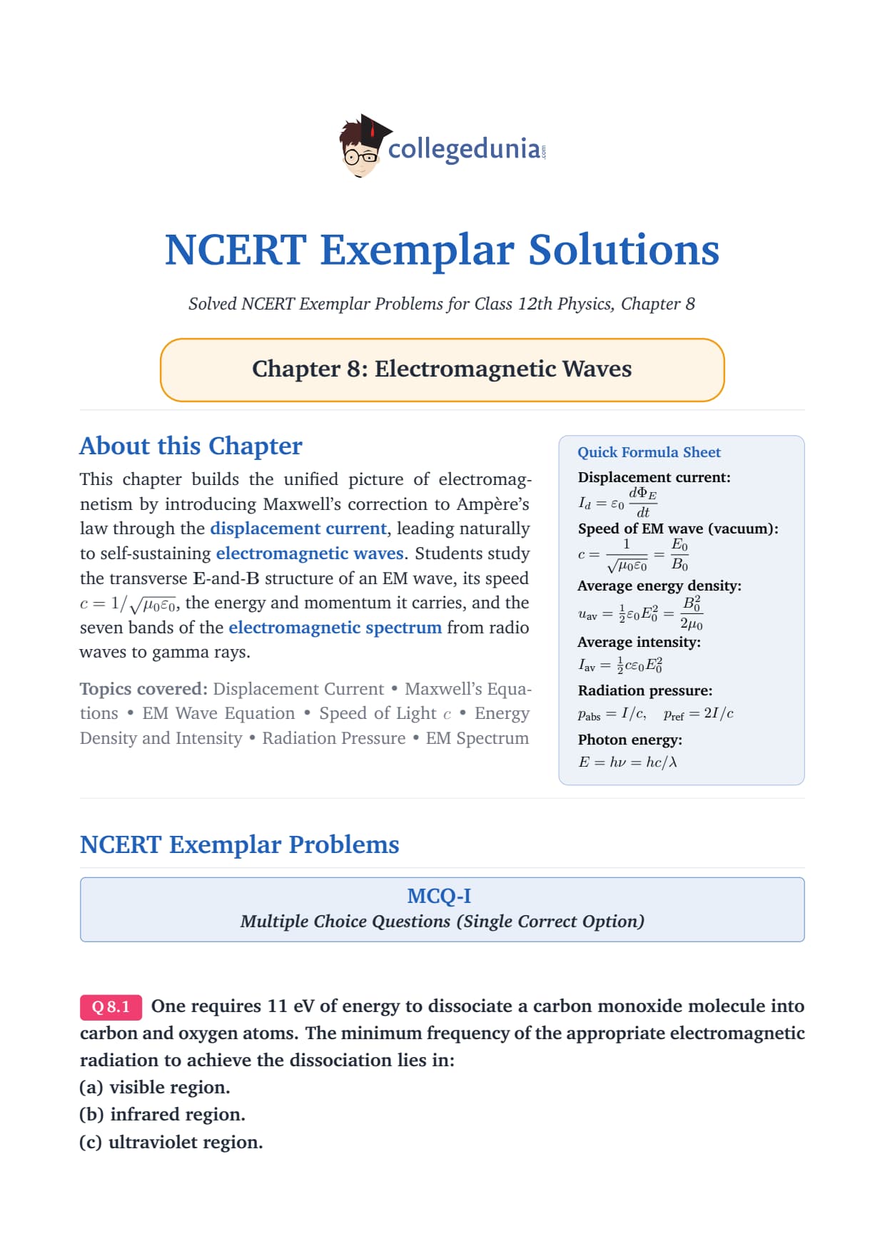
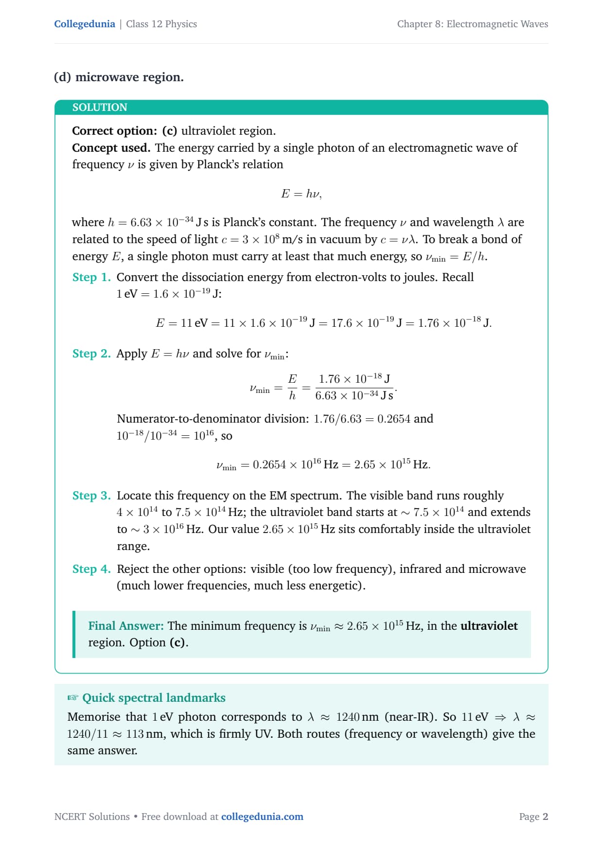
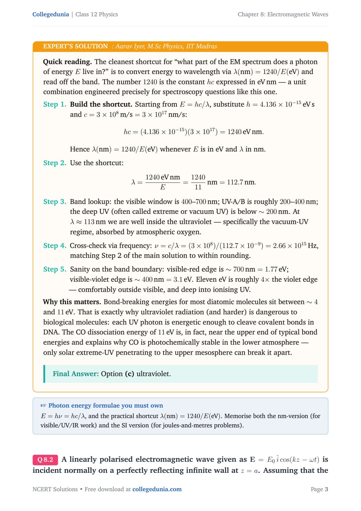
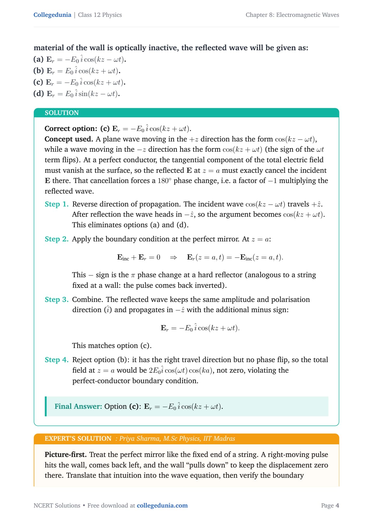


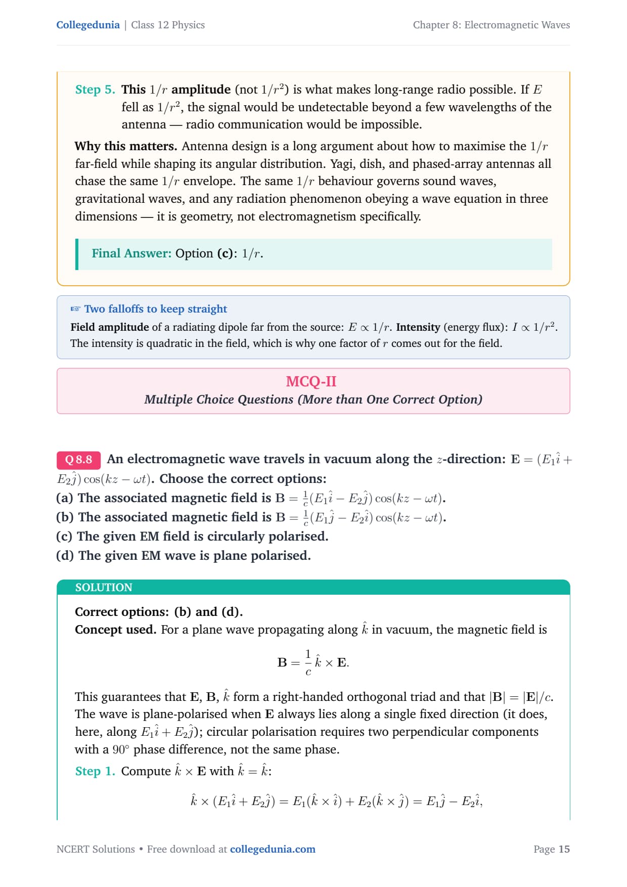
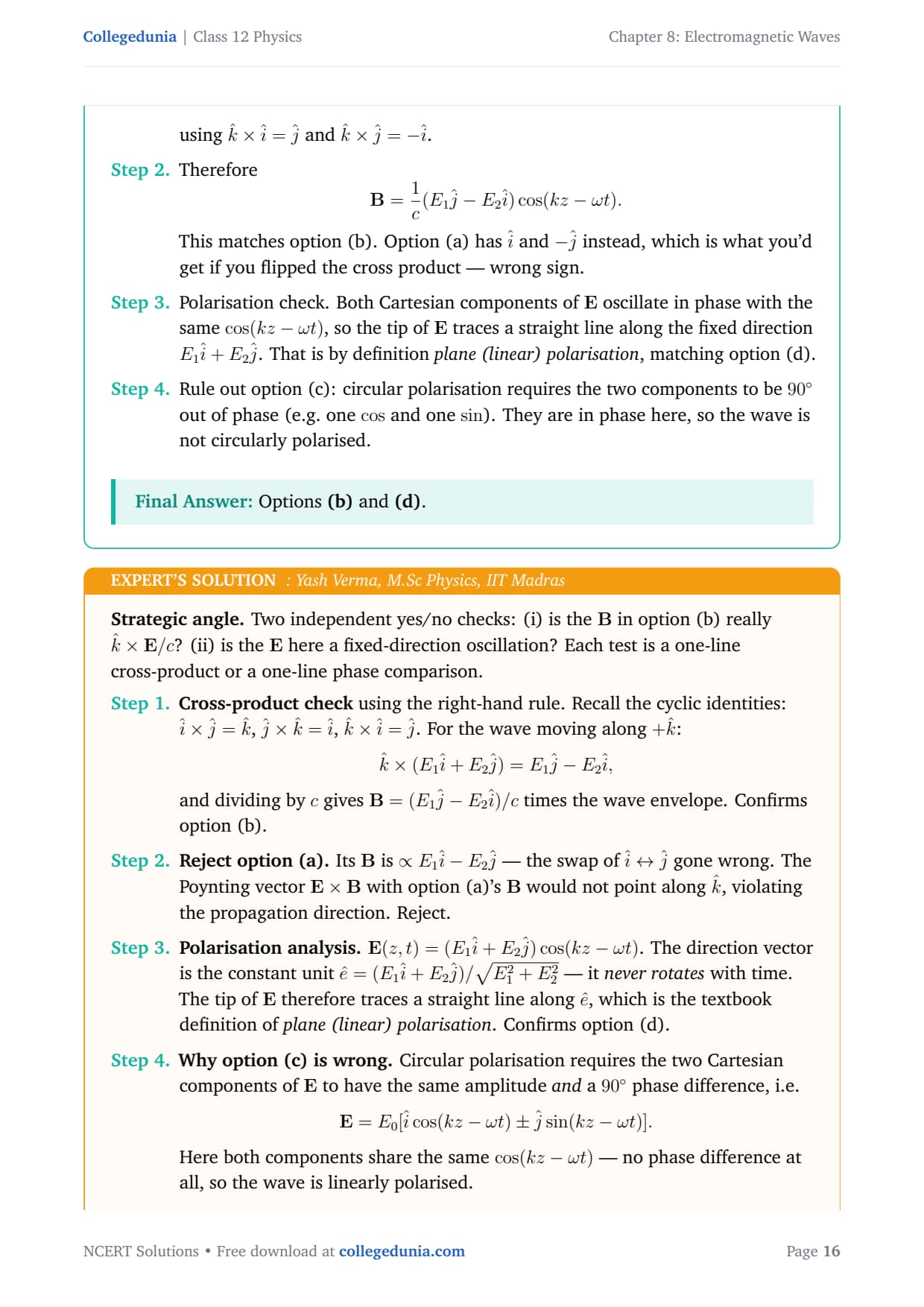
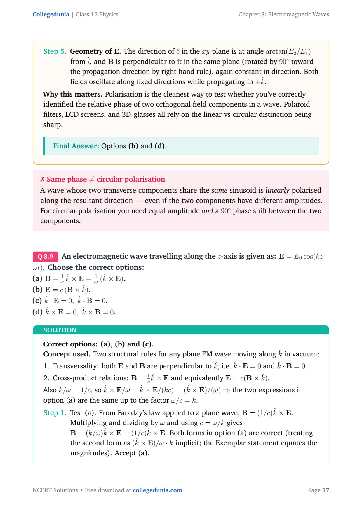
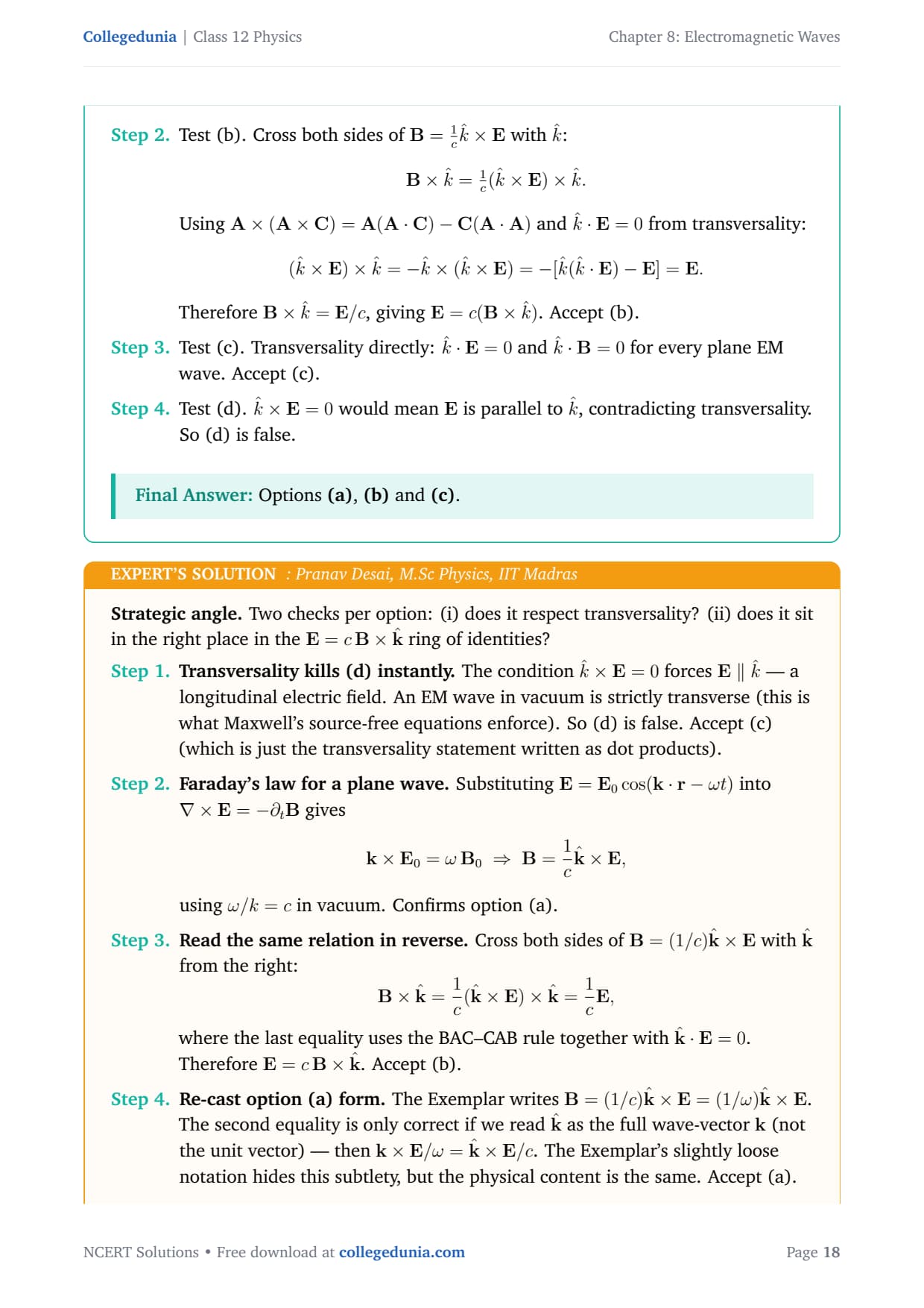



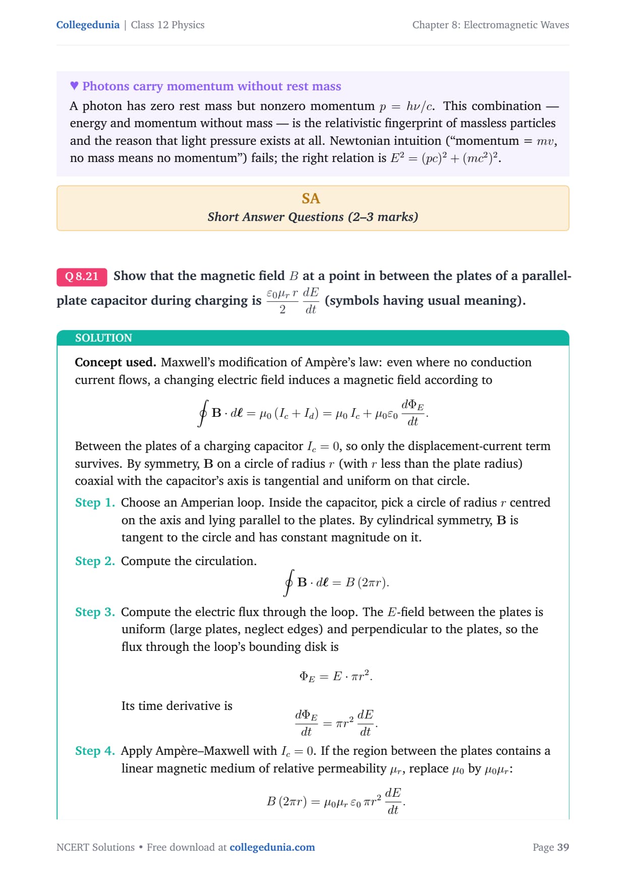
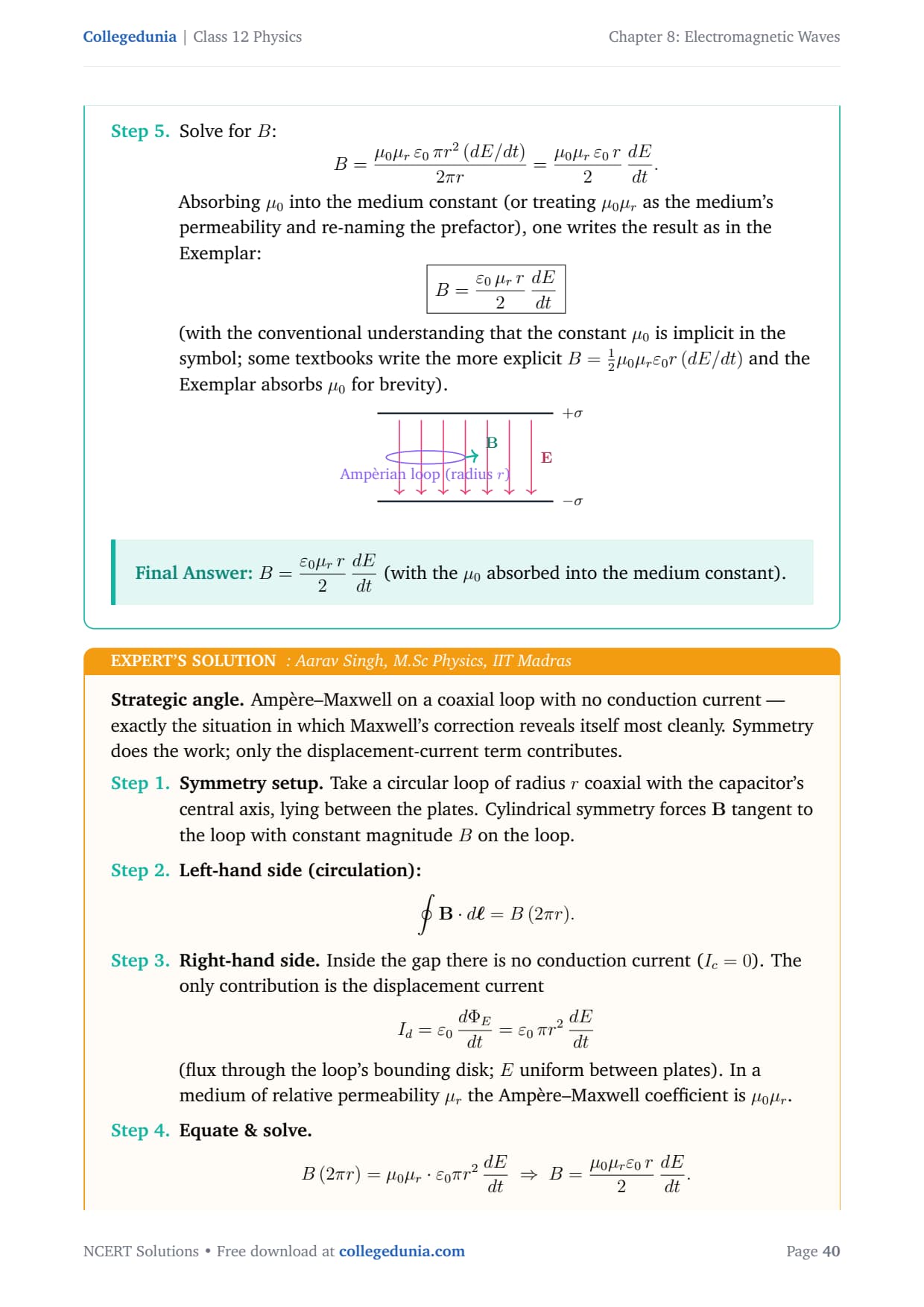
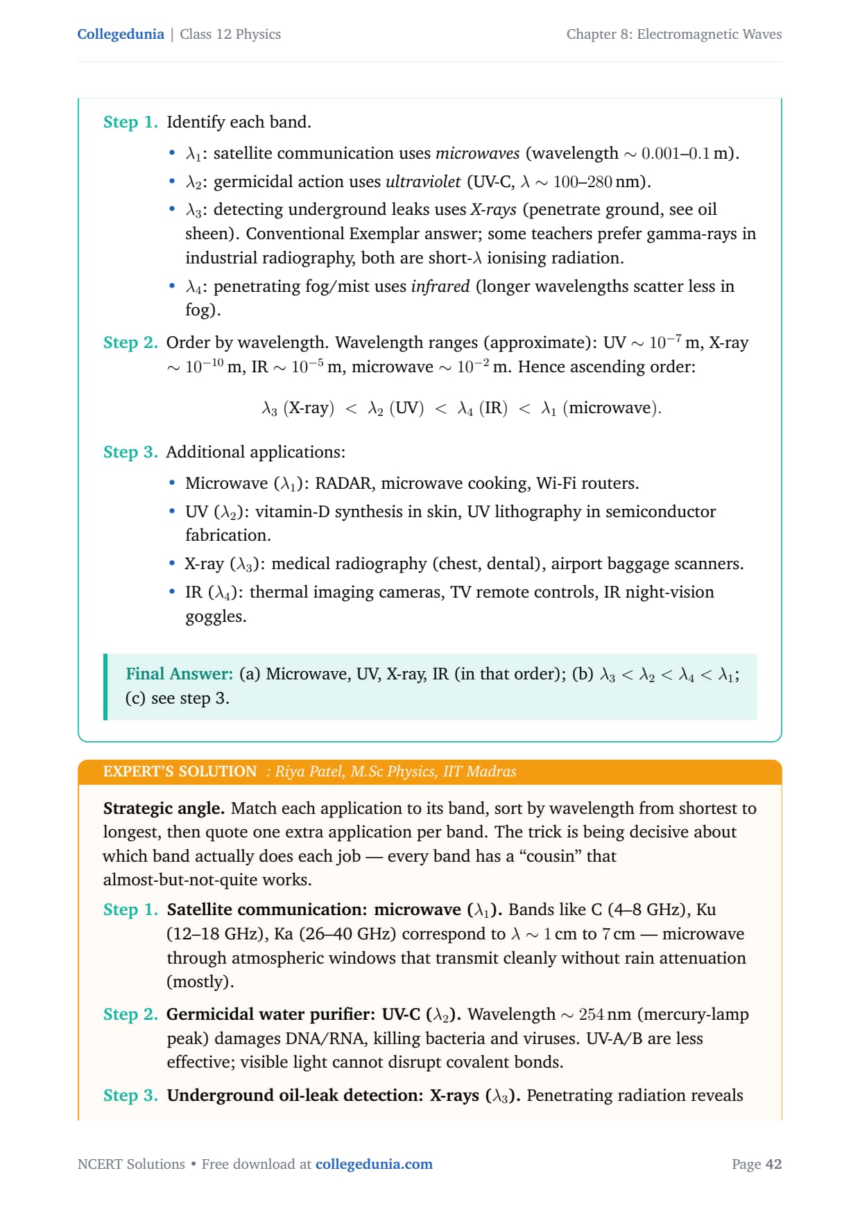

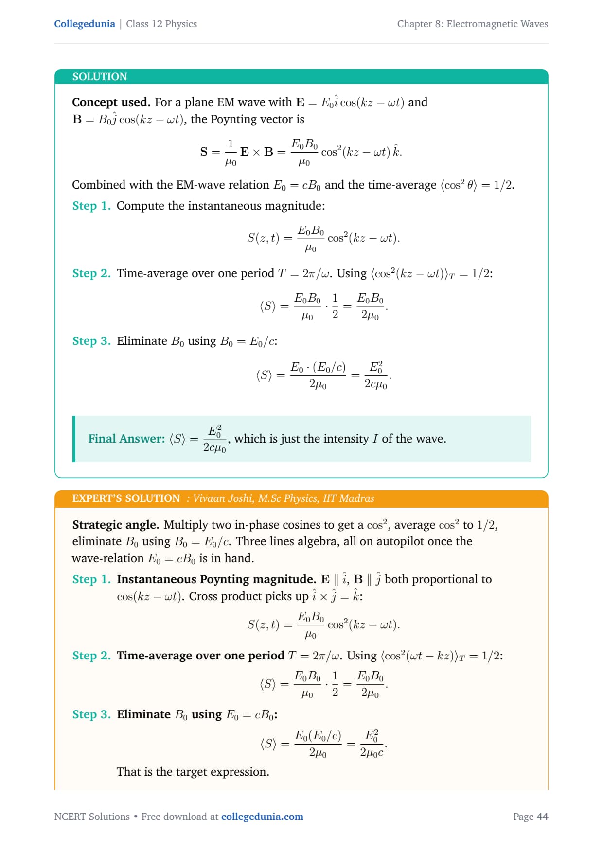
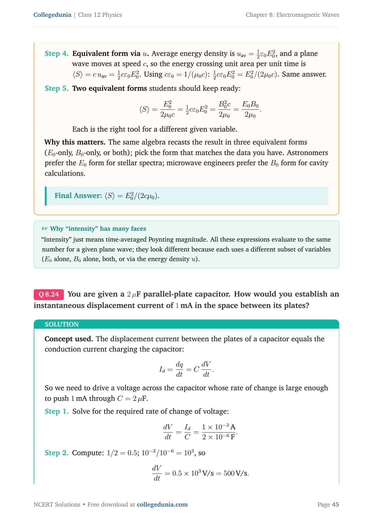
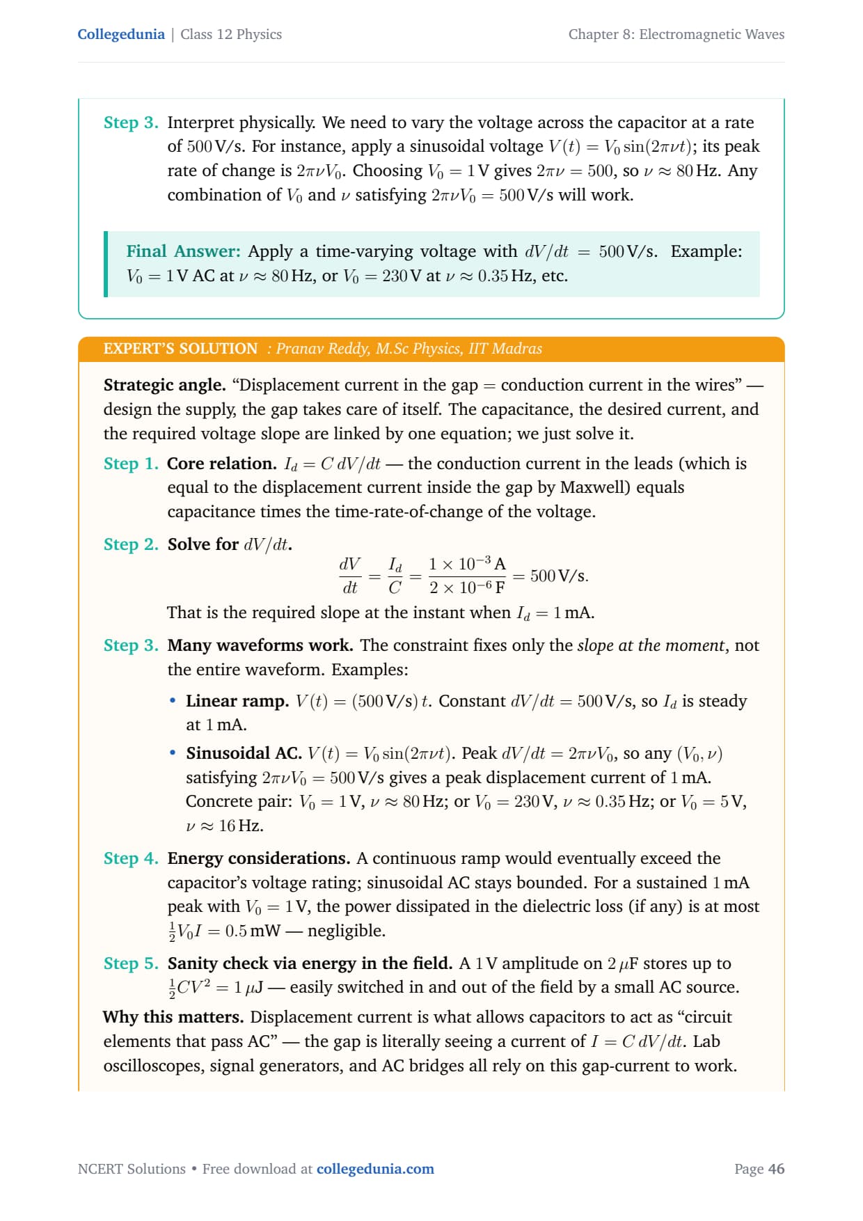

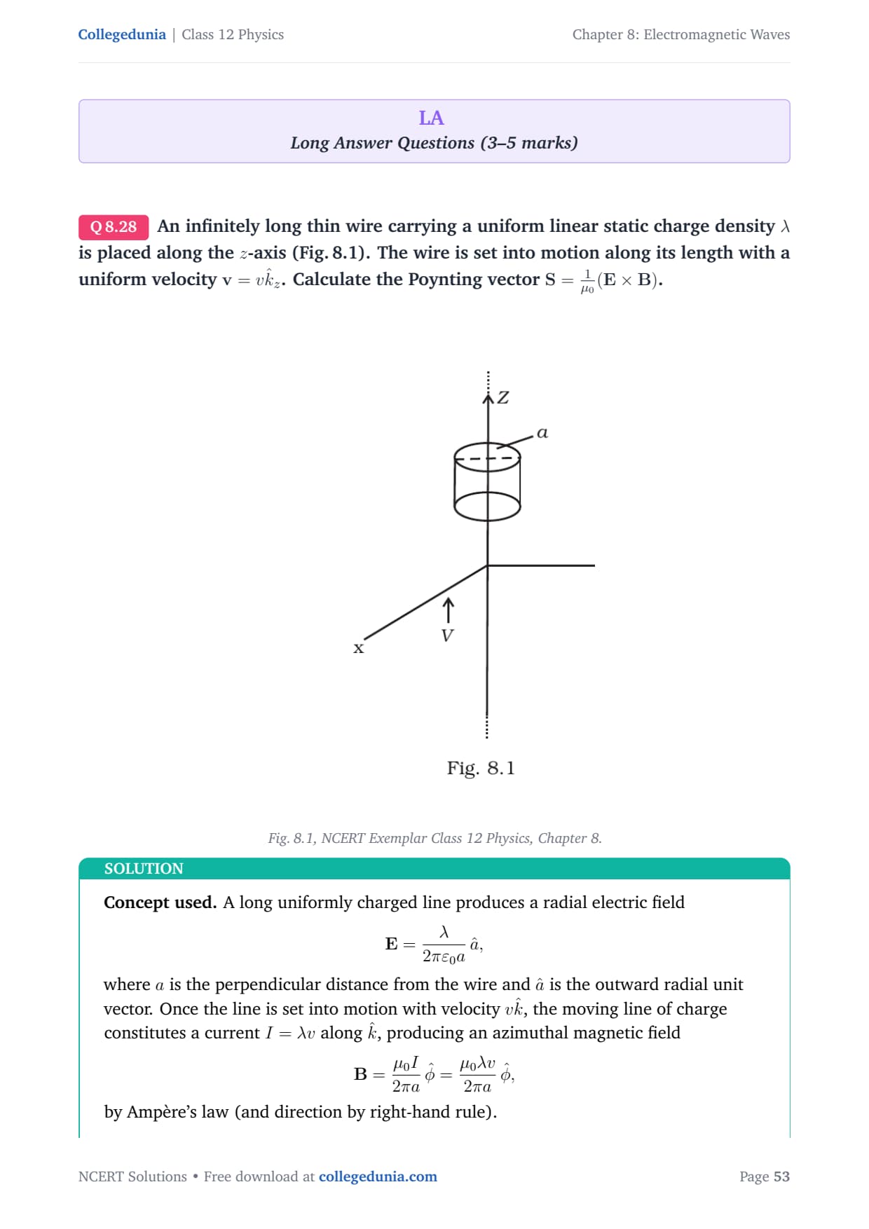

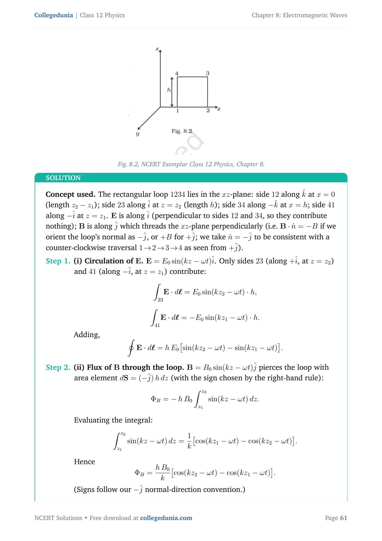
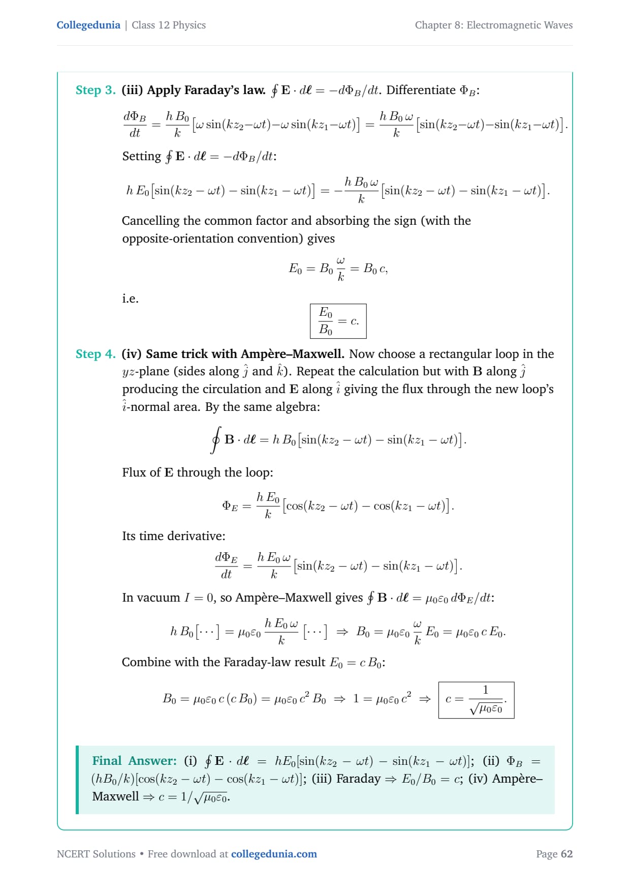
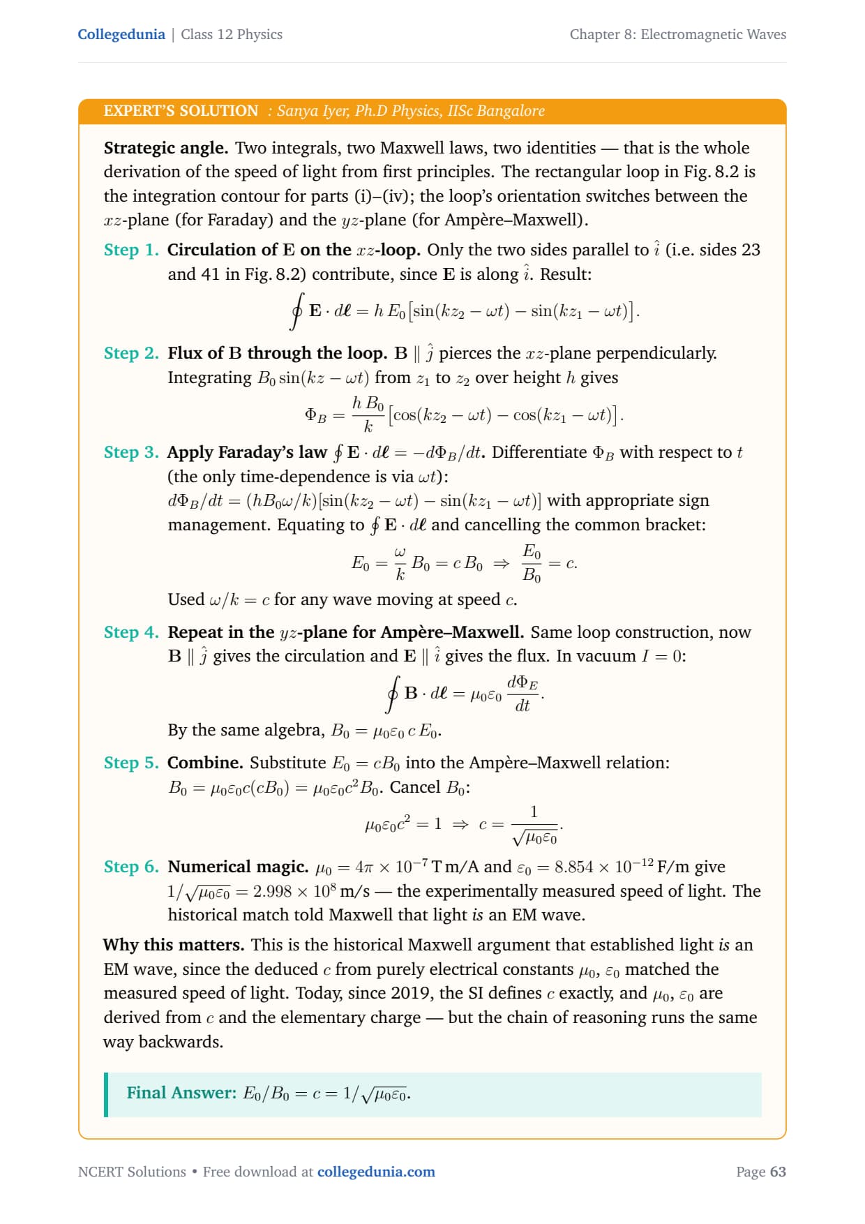
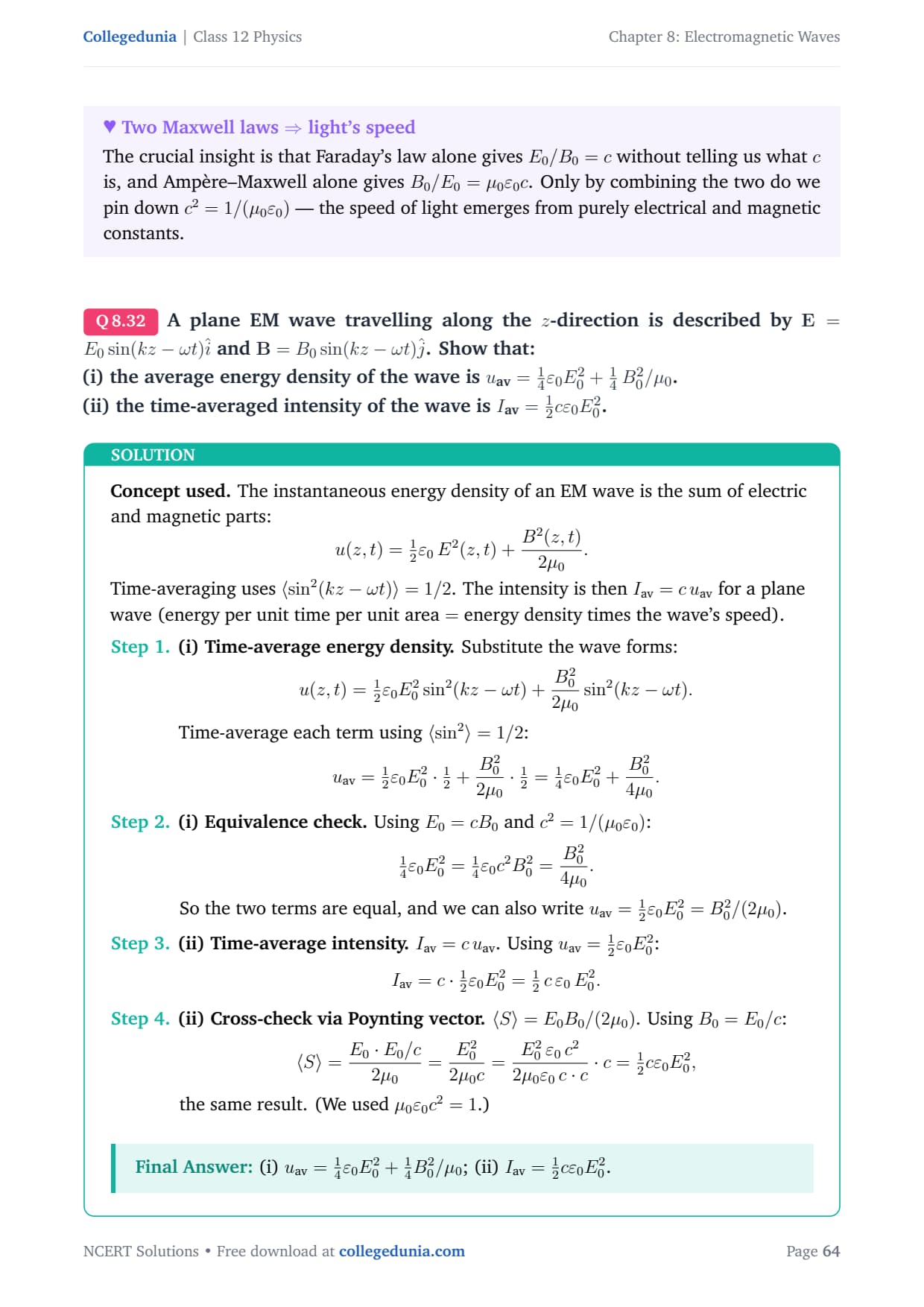
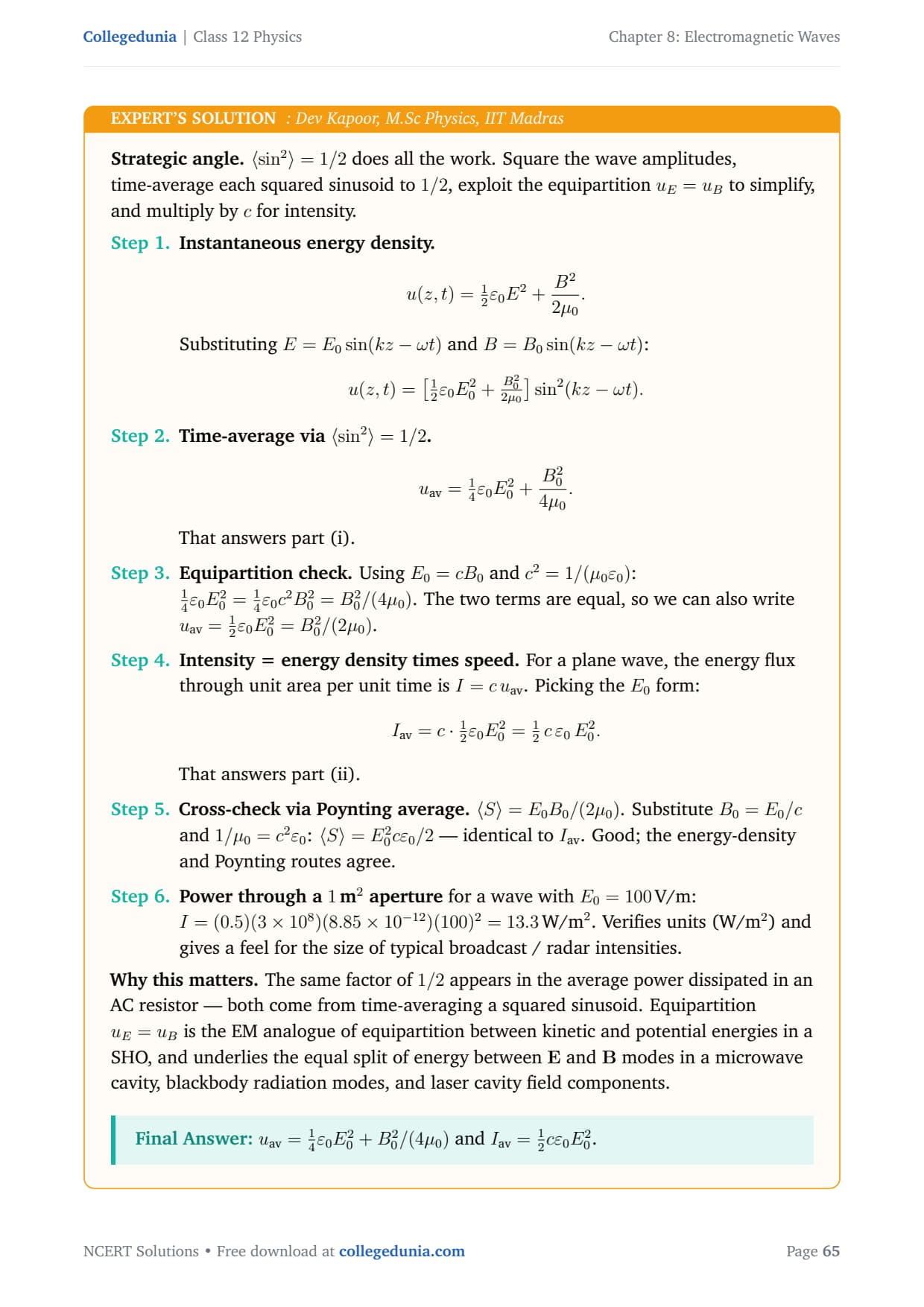
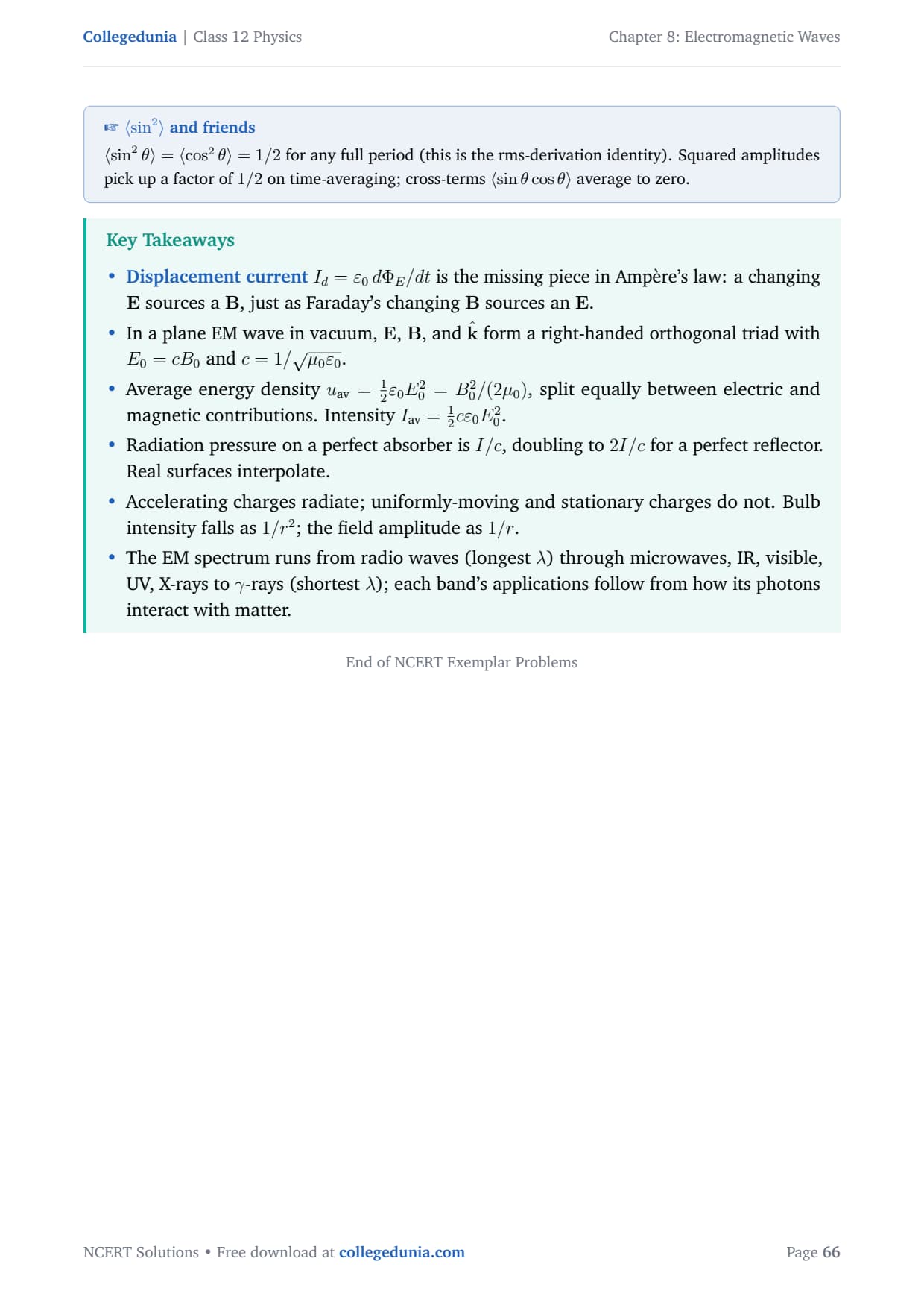
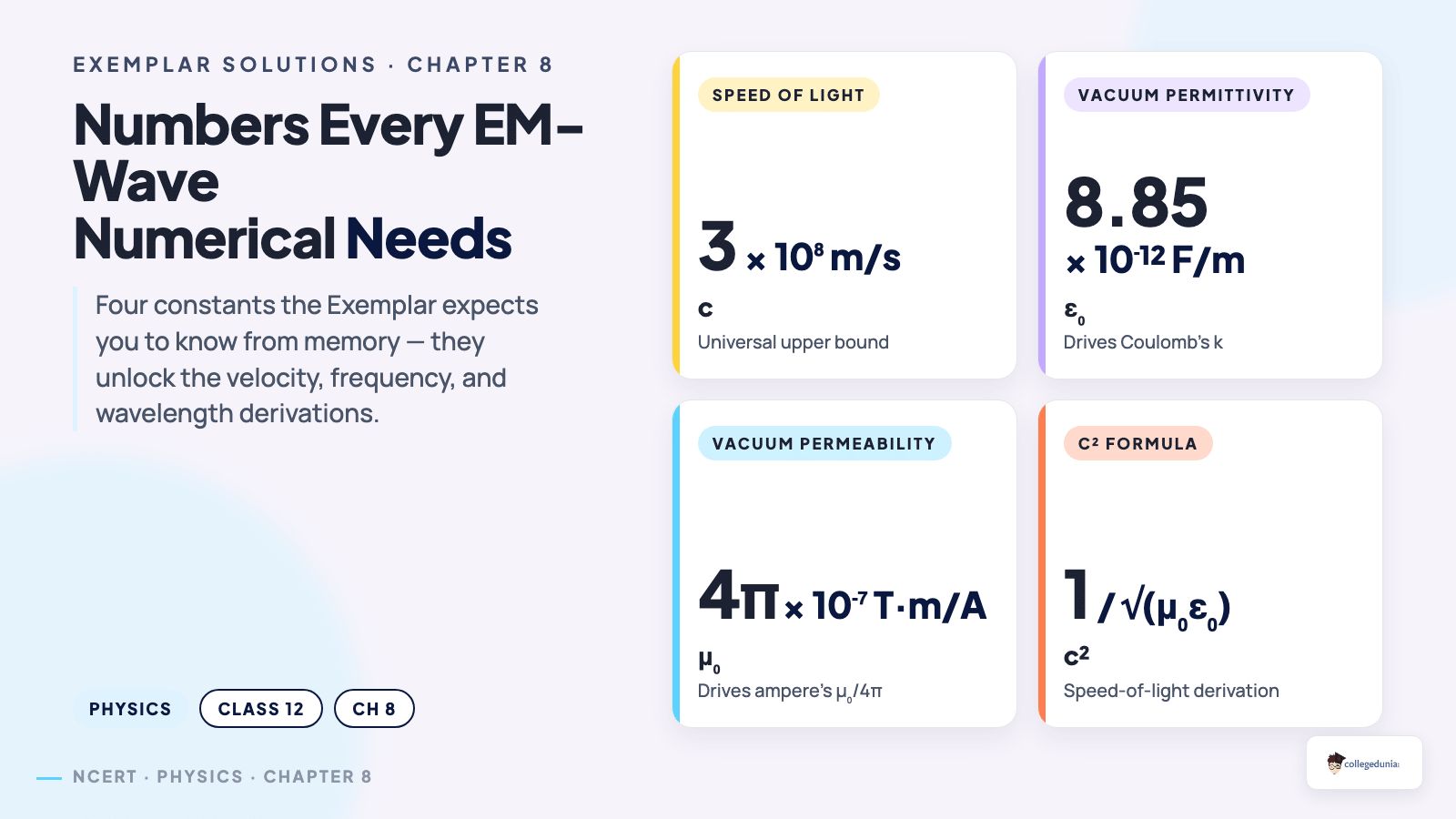
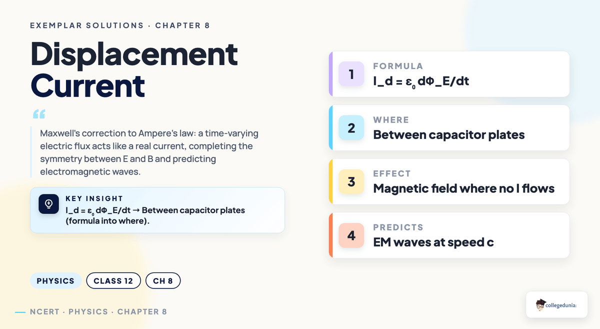



Comments