The NCERT Exemplar Class 12 Physics Solutions below is the fully solved companion to the NCERT Exemplar for Class 12 Physics Chapter 4 Moving Charges and Magnetism. Download the NCERT Exemplar Class 12 Physics Solutions once, then use it to check your own working line-by-line against an expert version. The NCERT Exemplar Class 12 Physics Solutions stays aligned with the 2026-27 syllabus.
CBSE Weightage: 5 to 7 marks (typically one short answer plus one numerical on cyclotron, moving-coil galvanometer, or solenoid)
JEE Main Weightage: 3 to 4% (roughly 1 question per shift, frequently on Ampere's law or magnetic force)
NEET Weightage: 2 to 3 questions per year
Both downloads of the NCERT Exemplar Class 12 Physics Solutions on this page are free and updated for the 2026-27 NCERT syllabus.
This NCERT Exemplar Class 12 Physics Solutions is curated by subject experts, mapped to the 2026-27 NCERT, and refined against the last five years of CBSE Board, JEE Main and NEET papers.
The 32 problems cover Biot-Savart law, Ampere's law, Lorentz force, current loops, cyclotron motion, and the moving-coil galvanometer.
Moving Charges and Magnetism Exemplar: MCQ, VSA, SA, LA Counts and Marks
The 32 problems split into a JEE-friendly upper half (MCQ) and a CBSE-friendly lower half (VSA, SA, LA).
Type
Problems
Time/Problem
Best Use For
MCQ-I
4.1 to 4.10
2 to 3 min
JEE Main, NEET, CBSE MCQ
MCQ-II
4.11 to 4.17
4 to 5 min
JEE Advanced, assertion-reason
VSA (1-2 marks)
4.18 to 4.24
3 to 4 min
CBSE Board short answers
SA (3 marks)
4.25 to 4.29
6 to 8 min
CBSE Board, NEET reasoning
LA (5 marks)
4.30 to 4.32
10 to 12 min
CBSE long-answer, JEE Adv
Quick Tip: JEE aspirants solve the 17 MCQ items first, then SA 4.25 and 4.27. NEET aspirants prioritise MCQ-I plus VSA 4.20 to 4.23.
Moving Charges and Magnetism NCERT Exemplar Video Solutions
Moving Charges and Magnetism Exemplar vs NCERT Textbook: Difficulty Step-Up
The textbook stays close to direct substitution the Exemplar adds geometry, multi-current setups, or a limit case.
Concept
NCERT Textbook Style
Exemplar Twist
Biot-Savart law
Field at the centre of a circular loop
Axial field with dipole-limit recovery (4.31)
Ampere's law
Field of an infinite straight wire
Field inside and outside a thick cylindrical conductor (4.32)
Force on a moving charge
Charge in uniform B
Helical motion with parallel and perpendicular components (4.18)
Force between parallel wires
Two equal parallel wires
Three-wire setup: force on the middle wire (4.16)
Current loop as dipole
State m = NIA
Torque on a triangular loop in a non-uniform field (4.28)
How will the NCERT Exemplar Class 12 Physics Solutions on Collegedunia Help You?
Each of the 32 problems carries a clean Solution plus an Expert's Solution naming every law used.
Every Type solved End-to-End: MCQ-I, MCQ-II, VSA, SA and LA, with reasoning written out, not just the final option.
Concept Stack Named: Each step labels the law: Biot-Savart, Ampere's law, Lorentz force, or τ = NIAB.
JEE and NEET Bridge: Items 4.13, 4.16, 4.27 and 4.31 are tagged with the JEE or NEET year that reused their scaffold.
2026-27 Aligned: All 32 problems remain in the current syllabus cyclotron and galvanometer were both retained.
Moving Charges and Magnetism Exemplar MCQ-II Solved: Multiple-Correct Walk-Through
MCQ-II is the most-failed type: students lock in the obvious option and miss the second correct choice. The verification pattern on Exemplar 4.14 is the fix.
Exemplar 4.14. A circular coil of radius R lies in the xy-plane. Which statement(s) about the magnetic field on the axis are correct? (a) Field is maximum at the centre (b) Field falls as 1/x^3 for x ≫ R (c) Field is zero on the axis (d) Field at x = R is 0I / 4√2R
(a) At x = 0, ( B = 0I / (2R) ), maximum on the axis. Selected.
(b) For x ≫ R, B ≈ 0I R2 / 2 x3. Selected.
(c) Axial field is non-zero confuses axis with equatorial plane. Rejected.
(d) At x = R, B = 0I R2 / [2(2 R2)3/2]= 0I / 4√2R. Selected. Answers: (a), (b) and (d).
This three-option setup appeared on JEE Main 2024 Session 2 and JEE Main 2023 Session 1.
Watch Out: The 1/x^3 limit is often misread as 1/x^2. Test the limit by substituting x ≫ R into the full Biot-Savart expression, never quote from memory.
Exemplar-Specific Common Mistakes in Moving Charges and Magnetism
These slip-ups recur across MCQ-II and SA submissions:
Quoting the cyclotron formula without the relativistic caveat.JEE Main 2024 Session 2 penalised this on a velocity-near-c question.
Using 0I / 2 π r for the field inside a thick conductor. For ( r < R ) the correct form is 0Ir / 2 π R2.
Forgetting the sinθ factor in Biot-Savart for a finite straight wire.
Treating a triangular loop as a circular loop for torque, missing the moment-arm geometry in 4.28.
Mis-directing the magnetic moment in the three-wire problem 4.16. This wiped 4 marks for NEET 2023 candidates.
How Frequently Has Moving Charges and Magnetism Been Asked in CBSE, JEE and NEET (Top 3 Recurring Topics)
Three Exemplar topics show up disproportionately often across the last five years.
Topic
Exemplar Item
Recurrence (last 5 years)
Biot-Savart on axis of a circular coil
4.14, 4.31
3 JEE Main + 2 NEET appearances
Force between parallel current-carrying wires
4.13, 4.16
2 CBSE Board + 2 JEE Main appearances
Cyclotron motion and moving-coil galvanometer
4.20, 4.27
2 NEET + 2 CBSE appearances
Class 12th Moving Charges and Magnetism Top 5 Formulae for Exemplar Numericals
These five formulae carry the bulk of the Exemplar SA and LA load.
Quantity
Formula
Biot-Savart law (current element)
dB⃗ = 04π · I dl⃗ × r̂}{r^2}
Field on the axis of a circular coil
B = 0I R2{2 R^2 + x^2^{3/2}}
Ampere's circuital law
∮ B⃗ · dl⃗ = 0 Ienc
Cyclotron frequency
f = qB / 2π m
Torque on a current loop
τ⃗ = NI A⃗ × B⃗
All NCERT Exemplar Questions for Moving Charges and Magnetism with Step-by-Step Solutions
Every question of the NCERT Exemplar set for Class 12 Physics Chapter 4 Moving Charges and Magnetism is listed below with its full Solution and Expert Solution hidden inside collapsible tabs. Click Check Solution to reveal the step-by-step working; click Expert Solution for the expanded explanation.
MCQ I (single correct option)
Q 4.1
Two charged particles traverse identical helical paths in a completely opposite sense in a uniform magnetic field B = B0k.
(A) They have equal z-components of momenta.
(B) They must have equal charges.
(C) They necessarily represent a particle–antiparticle pair.
(D) The charge to mass ratios satisfy (em)1 + (em)2 = 0.
Correct option: (D)(em)1 + (em)2 = 0.
Concept used. A charged particle moving in a uniform magnetic
field B describes a helix whose axis is along B. The
radius is r = mv⊥/(qB) and the pitch is
p = 2π m v∥/(qB). Two helices are
identical when their radii and pitches match, and
they are traversed in opposite sense when the rotation senses
about B are opposite. The rotation sense reverses when the sign
of q flips (for the same v).
Equal radii: m1 v⊥,1|q1|B = m2 v⊥,2|q2|B.
Equal pitches: m1 v∥,1|q1|B = m2 v∥,2|q2|B.
Both give m1|q1| = m2|q2| (taking equal
speeds), i.e. the magnitudes of e/m are equal.
Opposite sense of rotation requires q1 and q2 to have
opposite signs.
Combining the two conditions:
(em)1 = -(em)2
(em)1 + (em)2 = 0.
Why (A), (B), (C) fail: z-momenta could differ if masses
differ and pitch is fixed by m/q; charges need not be
equal, only opposite; the particles need not be a
true particle–antiparticle pair (e.g. a proton and a negative
muon have opposite signs but are not antiparticles).
Option (D): (e/m)1 + (e/m)2 = 0.
AS
Aarav Sharma
M.Sc Physics, IIT Madras
Verified Expert
Strategic angle. Rather than equating radius and pitch
separately, use the gyration frequency
c = qB/m which alone fixes both shape and sense. This single
scalar contains all the kinematic information about the helix and
saves you two equations.
Identical helices ⇒ equal |c|, hence
equal |q/m|. (The magnitude of c sets both the
radius via v⊥/c and the pitch via
2π v∥/c.)
Opposite sense ⇒c values are opposite in
sign, hence q/m values are opposite in sign. The sense of
rotation about B is the sign of c, full stop.
Combining: (q/m)1 = -(q/m)2, i.e. (q/m)1 + (q/m)2 = 0,
which is option (D).
Alternative angle –- physical interpretation. A
positive charge spirals one way and a negative charge of the
same |q/m| spirals the other way at the same rate. The
particle and ``mirror'' particle trace out identical helices in
opposite senses; this is exactly the scenario in the problem.
Cross-check with options. (A) Equal z-momenta would
require equal m v∥, but m can differ between the
two while m/|q| stays fixed. (B) Equal charges contradicts
the opposite-sense requirement. (C) Particle–antiparticle
pairs do satisfy (D), but the converse fails: an e- and
μ+ also satisfy (e/m)1 + (e/m)2 ≠ 0 in general but
a proton and an electron with carefully chosen kinetic
energies do not form a particle–antiparticle pair.
Why this matters. Helical motion is fully determined by
q/m and the velocity; mass and charge separately are not needed.
This is why mass spectrometers measure m/q, not m.
Option (D).
Q 4.2
Biot–Savart law indicates that the moving electrons (velocity v) produce a magnetic field B such that
(A) B ⊥ v.
(B) B ∥ v.
(C) it obeys inverse cube law.
(D) it is along the line joining the electron and point of observation.
Correct option: (A)B ⊥ v.
Concept used.Biot–Savart's law gives the magnetic
field dB produced by a small current element Id at
a point with position vector r from the element:
dB = 04πId× rr2.
For a single moving charge -e with velocity v, Id
is replaced by -ev, so
B ∝ v × r.
By definition of the cross product, v × r
is perpendicular to both v and r. Hence
B ⊥ v. Option (A) is correct.
(B) fails for the same reason: B cannot be parallel
to a vector to which it is perpendicular.
(C) fails: the magnitude varies as 1/r2, not 1/r3.
(D) fails: B is perpendicular to r, not along
it.
Option (A): B ⊥ v.
PI
Priya Iyer
Ph.D Physics, IISc Bangalore
Verified Expert
Quick reading. The Biot–Savart formula contains a
cross product; cross products always yield a vector
perpendicular to both factors. That single structural fact answers
the entire question without any geometry.
B ∝ v × r is the entire content of
the law for a point charge.
Perpendicularity is a property of the cross product, not of
any special geometry. So (A) holds in every configuration.
Magnitude scales with |v|sinθ / r2, ruling out
(C) (inverse cube) and (D) (along r).
Alternative method –- direct vector computation. Pick
an electron moving along +x with r along
+y; then v× r ∝ z. The
field at that observation point is along ± z, which
is perpendicular to both v (x) and r
(y). The construction generalises: any other choice of
r still gives a field perpendicular to v.
Why this matters. The perpendicularity of B to v
is what causes magnetic field lines to form closed loops around a
current; if B were along v they would diverge from the
charge like an electric field. This is why no magnetic monopoles are
observed –- the very algebra of Biot–Savart forbids a radial B.
Option (A).
Q 4.3
A current carrying circular loop of radius R is placed in the x-y plane with centre at the origin. Half of the loop with x>0 is now bent so that it now lies in the y-z plane.
(A) The magnitude of magnetic moment now diminishes.
(B) The magnetic moment does not change.
(C) The magnitude of B at (0,0,z), z≫ R increases.
(D) The magnitude of B at (0,0,z), z≫ R is unchanged.
Correct option: (A) The magnitude of magnetic moment now diminishes.
Concept used. The magnetic moment of a planar current loop
is M = IA, where A is the area vector (normal to
the plane of the loop, magnitude equal to the area enclosed). When
the loop is no longer planar, the moments of the two halves add as
vectors: Mnet = M1 + M2.
Before bending: full circle of radius R in the x-y plane
carrying current I. Magnetic moment magnitude:
M0 = I (π R2).
The direction is along z.
After bending: half-loop in the x-y plane has area
π R2/2, moment M1 = I(π R2/2) z. The
other half-loop in the y-z plane has area π R2/2,
moment M2 = I(π R2/2) x.
The net moment magnitude is
|M| = √M12 + M22
= √2Iπ R22
= Iπ R22 ≈ 0.707 M0.
Since 0.707 M0 < M0, the magnitude diminishes. (A) holds.
(C), (D) fail because B at large z along the axis is no
longer purely a dipole field of strength M0; the dipole
moment along z alone is M1 = M0/2, so the on-axis
field decreases.
Option (A): magnetic moment diminishes to
M0/√2.
VG
Vivaan Gupta
M.Sc Physics, IIT Bombay
Verified Expert
Picture-first. Two perpendicular half-discs of equal area
behave like the legs of a right triangle: the vector sum is
2 times one leg, not 2 times. The bend has split a single
z-aligned moment of magnitude M0 into two halved moments
along z and x, and their orthogonal addition yields
M0/2.
Each half-disc carries half the original area. Treating each
as a half-loop with the wire current I, the magnitude of
each moment is |M1| = |M2| = Iπ R2/2 = M0/2.
These two moments are perpendicular (z and x).
Their resultant has magnitude
√(M0/2)2 + (M0/2)2 = M0/2 ≈ 0.707 M0.
M0/2 ≈ 0.71 M0 < M0. So the moment shrinks.
Alternative method –- continuous deformation. Imagine
slowly bending the right half through angles 0,π/6,π/3,π/2.
The z-component of the right half's moment falls as
cosφ while a new x-component grows as sinφ.
At φ = π/2 the z-component of the right half is 0,
the x-component is M0/2, and combined with the unchanged
left half (M0/2 along z) the resultant magnitude is
M0/2. Same answer, by tracking the geometry.
Numerical sanity check.M0/2 = 0.707 M0, so
the on-axis dipole field at large z falls by the same factor
1/2 ≈ 0.71 (since dipole field ∝ M). The
field does decrease, confirming options (C), (D) are wrong.
Why this matters. For a vector quantity, geometry matters:
splitting along orthogonal directions does not preserve the
magnitude. This is the same effect that makes the magnetic moment of
a folded coil less than that of the flat one –- a fact exploited in
magnetic-shielding design.
Option (A).
Q 4.4
An electron is projected with uniform velocity along the axis of a current carrying long solenoid. Which of the following is true?
(A) The electron will be accelerated along the axis.
(B) The electron path will be circular about the axis.
(C) The electron will experience a force at 45∘ to the axis and hence execute a helical path.
(D) The electron will continue to move with uniform velocity along the axis of the solenoid.
Correct option: (D) continues with uniform velocity along the axis.
Concept used. Inside a long solenoid the magnetic field is
uniform and directed along the axis: B = Bn where
n is the axial unit vector. The magnetic force on a charge q
moving with velocity v is F = qv × B.
Here v = v0n (electron moves along the axis)
and B = Bn.
Compute the magnetic force:
F = -e (v0n) × (Bn)
= -e v0B (n × n)
= 0.
(Any vector crossed with itself gives zero.)
With zero net force, Newton's first law says the electron
keeps moving with the same velocity along the axis. Option
(D) holds.
(A), (B), (C) all require a non-zero force, which does not
exist here.
Option (D): electron moves with uniform velocity along the axis.
AM
Aanya Mehta
B.Tech Engineering Physics, IIT Bombay
Verified Expert
Strategic angle. The cross product vanishes when the two
vectors are parallel. Spot this and the answer is immediate; no
calculation required.
Velocity is along axis; field is along axis. Parallel.
v × B = 0, so Fmag = 0.
No force, no acceleration. Uniform motion continues.
Alternative method –- decompose the velocity. Write
v = v∥n + v⊥. The general
motion in a solenoid would be helical: the parallel piece
slides along n unaffected, and the perpendicular piece
circles at c = eB/m. Here v⊥ = 0, so the
circle collapses to a point and only the parallel slide
remains –- straight-line uniform motion.
Concept linkage. This is exactly the principle of
magnetic confinement in fusion devices: charged particles
spiral tightly around field lines but slide freely along
them, just like the electron here.
Why this matters. A solenoid acts as a velocity filter:
charges moving along its axis are unaffected, while charges with a
transverse component spiral. The same physics underlies
charged-particle beams in mass spectrometers and electron-microscope
columns.
Option (D).
Q 4.5
In a cyclotron, a charged particle
(A) undergoes acceleration all the time.
(B) speeds up between the dees because of the magnetic field.
(C) speeds up in a dee.
(D) slows down within a dee and speeds up between dees.
Correct option: (A) undergoes acceleration all the time.
Concept used. A cyclotron has two semicircular metallic
hollow chambers (dees). Inside the dees the magnetic field
keeps the charge on a circular arc; in the gap between the dees an
oscillating electric field speeds the charge up. Centripetal
acceleration is non-zero whenever the path curves.
Inside a dee: |v| is constant but direction keeps
changing along a circular arc. Acceleration magnitude
a = v2/r ≠ 0 (centripetal).
In the gap between the dees: the electric field along the
gap exerts force F = qE on the charge,
accelerating it tangentially (speeding it up).
In both regions acceleration is non-zero. Hence (A): the
particle is accelerated all the time.
(B) fails because the speed increase happens in the
electric field (gap), not the magnetic field. (C) is wrong:
speed stays constant inside the dee. (D) is wrong: speed
does not decrease inside the dee.
Option (A): the cyclotron particle is accelerated continuously.
AK
Arjun Kapoor
M.Sc Physics, IIT Madras
Verified Expert
Strategic angle. Acceleration includes change in direction,
not just change in speed. Once that is clear, (A) is the only choice;
the magnetic-field dee region and the gap each provide their own
non-zero a.
Centripetal acceleration in the dees: speed fixed, direction
rotates, ac = v2/r pointed toward the centre of the
arc, a ≠ 0.
Tangential acceleration in the gap: speed grows under
F = qE, magnitude at = qE/m, a ≠ 0.
Net: acceleration is non-zero throughout the orbit, so (A).
Quantitative check. For protons in a 1.5 T cyclotron
at radius r = 0.5 m: v = qBr/m = (1.610-19)(1.5)(0.5)/(1.67× 10-27) ≈ 7.2× 10⁷ m/s, so ac = v2/r ≈ 1.0× 10¹⁶ m/s2. Even inside the dee the acceleration is enormous –- option (A) is unambiguously right.
Alternative angle –- energy ledger. In the dee, the
magnetic force does no work (F⊥ v), so kinetic
energy stays constant. In the gap, the electric force does
positive work each time, and the kinetic energy grows. Both
regions feature non-zero a, even though the energy
story is different in each.
Why this matters. The cyclotron is the textbook
demonstration that constant-magnitude circular motion is still
accelerated motion –- a fact that students often miss when they
conflate ``speed'' with ``velocity''. Real cyclotrons exploit this
duality: the dees provide the geometric (centripetal) turning, the
gap provides the energy injection.
Option (A).
Q 4.6
A circular current loop of magnetic moment M is in an arbitrary orientation in an external magnetic field B. The work done to rotate the loop by 30∘ about an axis perpendicular to its plane is
(A) MB.
(B) 3 MB2.
(C) MB2.
(D) zero.
Correct option: (D) zero.
Concept used. The potential energy of a magnetic dipole in
an external field is U = -M· B = -MBcosθ, where
θ is the angle between M and B. The magnetic
moment vector M of a flat current loop is perpendicular
to the plane of the loop. Rotating the loop about an axis
perpendicular to its plane keeps M along the same
direction.
Initial orientation: M makes some angle θ with
B. So Ui = -MBcosθ.
Rotation axis is perpendicular to the plane of the loop,
i.e. along M itself. Rotating about M does
not change M's direction; only the loop spins
about that direction.
Final orientation: M still makes angle θ with
B, so Uf = -MBcosθ = Ui.
Work done by external agent = Δ U = Uf - Ui = 0.
Option (D).
(A), (B), (C) all assume the rotation tilts M away
from B, which a perpendicular-axis spin does not do.
Option (D): W = 0.
AN
Aditya Nair
Ph.D Physics, IISc Bangalore
Verified Expert
Strategic angle. Identify the rotation axis first; the
behaviour of M follows. The axis-direction is doing all the
work in this problem.
Loop plane ⊥ M, so the rotation axis (perpendicular
to plane) is parallel to M.
A vector rotated about its own direction is unchanged: the
rotation matrix about M fixes M.
Energy depends only on M· B. With M
unchanged, U unchanged, W = 0.
Alternative method –- torque integral. Work done by
an external agent rotating the loop by dθ at angle
θ against the field torque is
dWext = -ext· dθ = MBsinθ dθ,
but here dθ is along M and τ = M×B is perpendicular to M; their dot product is
zero for every dθ. So ∫ dW = 0 irrespective of
the 30∘. Same answer.
Concept linkage. A free coil in a magnetic field
precesses about its own axis (like a top about gravity) –-
the precession does no work against the field for exactly
this reason. Galvanometer suspension wires exploit this
to allow rotation without energy loss into the magnetic
background.
Why this matters. It explains why a freely-rotating coil
about its own axis in a uniform field does not exchange energy with
the field; only the alignment with B matters.
Option (D).
MCQ II (one or more correct options)
Q 4.7
The gyro-magnetic ratio of an electron in an H-atom, according to Bohr model, is
(A) independent of which orbit it is in.
(B) negative.
(C) positive.
(D) increases with the quantum number n.
Correct options: (A) and (B).
Concept used. The gyro-magnetic ratio of a charged
particle in orbital motion is the ratio of its magnetic moment to its
orbital angular momentum,
γ = ML = q2m.
This expression is independent of the orbit's radius and the speed.
For an electron, q = -e < 0, so γ is negative.
For a charge q in a circular orbit of radius r with speed
v:
M = I · π r2 = qTπ r2,
T = 2π rv.
So M = qvr2.
Angular momentum: L = mvr. Hence
γ = ML = qvr/2mvr = q2m.
This depends only on q/m, not on r, v or n. So (A) is
correct, and (D) is wrong.
For an electron, q = -e, so γ = -e/(2me) < 0.
Option (B) is correct; (C) is wrong.
Options (A) and (B).
RS
Riya Singh
M.Sc Physics, IIT Madras
Verified Expert
Structural observation. The cancellation of r and v in
the ratio M/L is the key. Once that is seen, the orbit
dependence disappears and the answer follows from the sign of q
alone.
Magnetic moment of orbit: M = qvr/2 (treat orbit as
current loop with effective current I = q/T = qv/(2π r),
area π r2).
Orbital angular momentum: L = mvr.
Ratio: γ = q/(2m), no r or v or n.
Sign of γ = sign of q. Electron: q = -e, so
γ = -e/(2me) < 0.
Alternative method –- Bohr-radius formulation. In
Bohr's model rn = n2 a0, vn = v1/n. So
M(n) = qvnrn/2 = (q/2)(v1/n)(n2 a0) = (nq v1 a0)/2
and Ln = nm v1 a0. Their ratio M(n)/Ln = q/(2m),
with all the n-dependence cancelling. Same answer.
Concept linkage. The Bohr magneton
B = e/(2me) pops out from this when L = is
substituted. So γ is the constant of proportionality
between angular momentum and the magnetic dipole moment –-
a recurring theme in atomic and nuclear physics.
Why this matters. The same logic gives the electron's spin
g-factor close to -1 for orbital motion; spin requires the
relativistic correction g ≈ -2. The orbital gyro-magnetic
ratio is the simplest manifestation of a deep symmetry between
angular momentum and magnetic moment.
Options (A), (B).
Q 4.8
Consider a wire carrying a steady current, I placed in a uniform magnetic field B perpendicular to its length. Consider the charges inside the wire. It is known that magnetic forces do no work. This implies that,
(A) motion of charges inside the conductor is unaffected by B since they do not absorb energy.
(B) some charges inside the wire move to the surface as a result of B.
(C) if the wire moves under the influence of B, no work is done by the force.
(D) if the wire moves under the influence of B, no work is done by the magnetic force on the ions, assumed fixed within the wire.
Correct options: (B) and (D).
Concept used. The magnetic force on a moving charge is
F = qv × B, always perpendicular to v, so
the instantaneous power F · v = 0: magnetic forces do
no work on the charge. However, the lateral push on the drift
electrons is real; in equilibrium it must be balanced by an electric
field set up by surface charges (the Hall effect).
Inside the wire, drift electrons feel a transverse magnetic
force. They drift sideways until they pile up on one face of
the wire (a Hall-type charge separation). So (B) is correct
and (A) is wrong (the motion is affected even though
no energy is absorbed).
If the wire as a whole moves with velocity u under
B, the ions (lattice) move with velocity u.
The magnetic force on each ion is qu× B,
which is ⊥ u, so it does no work on the
ions. Hence (D) is correct.
(C) is too strong: the wire can do mechanical work
(e.g. rotating a coil in a motor) because the Hall-balancing
electric field, originally set up by B, transmits force
to the lattice. The first law still applies: it is the
source maintaining the current that supplies the
energy.
Options (B) and (D).
KB
Karan Bhat
Ph.D Condensed Matter Physics, TIFR Mumbai
Verified Expert
Strategic angle. Separate force on charges (drift electrons)
from force on the bulk (ions). Magnetic forces do no work
on the carrier they push, but the carriers can transfer
momentum via internal fields.
Drift electrons feel transverse F; they pile up on the
wire surface. (B) follows.
For a wire moving under B: ions move with the wire.
F on ions is ⊥ u, so no work on ions.
(D) follows.
(A) and (C) are too sweeping: (A) ignores Hall accumulation;
(C) confuses ``no work on the charges'' with ``no work on the
wire''.
Why this matters. This is the principle behind every
electric motor: magnetic forces do no work on individual carriers,
yet a motor delivers mechanical power because the carriers transmit
the force to the lattice. The energy ledger ties back to the battery
maintaining the current, not to the magnetic field as a source.
Alternative angle –- microscopic check. The instantaneous
power on a single drift electron is F· v = q(v× B)· v = 0
identically. Sum over ∼ 1028 m-3 electrons and
the integrated power is still zero per electron. The macroscopic
power comes from the Hall electric field, which is a real, work-doing
E even though it originated from a magnetic field.
Options (B), (D).
Q 4.9
Two identical current carrying coaxial loops, carry current I in an opposite sense. A simple amperian loop passes through both of them once. Calling the loop as C,
(A) CB · d= 20I.
(B) the value of CB · d is independent of sense of C.
(C) there may be a point on C where B and d are perpendicular.
(D) B vanishes everywhere on C.
Correct options: (B) and (C).
Concept used.Amp`ere's circuital law states
CB · d= 0 Ienc, where
Ienc is the algebraic sum of currents threading the
Amperian loop C (sign by right-hand rule).
The two loops carry currents +I and -I through the same
Amperian loop C. Net enclosed current:
Ienc = +I + (-I) = 0.
Hence
CB · d= 0(0) = 0.
So (A) is wrong.
Since the integral is 0, it is unchanged whether C is
traversed clockwise or anticlockwise; the value 0 is
independent of sense. (B) is correct.
B is non-zero away from the wires (each loop produces
its own field). On C there may be points where the
local field is perpendicular to d, contributing
zero to the integrand locally. (C) is correct.
(D) is too strong: B is generally non-zero on C;
only the line integral is zero.
Options (B) and (C).
AJ
Ananya Joshi
M.Sc Astrophysics, IIT Kanpur
Verified Expert
Strategic angle. Distinguish ``integral = 0'' from
``integrand = 0''. The first holds because currents cancel; the
second does not. The line integral is a global property; the
integrand is a local one.
Ienc = I - I = 0 ⇒ integral = 0.
A scalar that equals 0 has the same value under reversal of
the integration sense. (B) follows.
Local B ⊥ d on parts of C is consistent
with non-zero B. (C) follows.
Field-cancellation everywhere on C (option D) would require
B = 0 globally, contradicted by Biot–Savart for each
loop (each loop alone produces a non-zero field everywhere
except on its own axis).
Alternative method –- superposition. Apply Amp`ere's
law to each loop separately. For loop 1 alone:
C B1 · d= +0I. For loop 2 alone:
C B2 · d= -0I (opposite sense).
Their sum is zero. The local field B = B1 + B2
is non-zero at any generic point.
Concept linkage. This is the principle behind
anti-Helmholtz coils used in magneto-optical traps: opposing
currents give zero net field at the centre but a strong
gradient that confines cold atoms.
Why this matters. Helmholtz coils and anti-Helmholtz coils
exploit exactly this difference between net enclosed current and
local field. Modern ion-trap experiments depend on getting this
distinction right.
Options (B), (C).
Q 4.10
A cubical region of space is filled with some uniform electric and magnetic fields. An electron enters the cube across one of its faces with velocity v and a positron enters via opposite face with velocity -v. At this instant,
(A) the electric forces on both the particles cause identical accelerations.
(B) the magnetic forces on both the particles cause equal accelerations.
(C) both particles gain or loose energy at the same rate.
(D) the motion of the centre of mass (CM) is determined by B alone.
Correct options: (B), (C) and (D).
Concept used. For an electron (-e, mass m) and a positron
(+e, mass m) in the same E,B field: the electric force
FE = qE has opposite sign for the two; the magnetic
force FB = qv×B involves bothq and
v, and both flip when going from electron to positron, so the
net magnetic force is the same.
Electron: FE(e-) = -eE.
Positron: FE(e+) = +eE.
Opposite directions ⇒ accelerations
(a = F/m) are opposite, not identical.
So (A) is wrong.
Power delivered by E on a charge is FE·v.
Electron: (-eE)·v = -eE·v.
Positron: (+eE)·(-v) = -eE·v.
Same rate of energy change. (C) is correct.
The centre-of-mass momentum is pCM = mv + m(-v) = 0.
Net electric force on the system is -eE + (+eE) = 0, so E contributes nothing to CM motion. The two magnetic forces (computed in step 2) are equal, summing to a non-zero 2FB(e-), which alone drives the CM. (D) is correct.
Options (B), (C), (D).
KR
Krishna Reddy
M.Tech Applied Physics, IIT Delhi
Verified Expert
Strategic angle. Track how each force depends on the sign of
charge and the sign of velocity. Electric: only on q. Magnetic: on
qv, so on the product. This separation immediately
sorts the options.
Electric force flips between e- and e+ (different q).
Accelerations are equal in magnitude but opposite. Rule out (A).
Magnetic force is the same on both because both q and
v flip and their product is unchanged. (B), and
consequently (D) for the CM.
Power FE·v flips twice (in q and in v),
so it is the same number. (C).
Alternative method –- CM coordinates. The CM of the
electron–positron system moves at (mv + m(-v))/(2m) = 0
at t = 0. The net external electric force is
-eE + (+eE) = 0, so E never accelerates the
CM. The net magnetic force is 2FB(e-) ≠ 0 in
general, so it alone drives the CM. (D) follows from
Newton's-second-law for the CM.
Concept linkage. Annihilation experiments (such as
positron-emission tomography, PET) rely on the symmetric
kinematics of an e+e- pair: the two photons emitted in
opposite directions can be tracked precisely because the
magnetic environment treats both particles identically.
Why this matters. This is exactly the symmetry that makes
e+ e- pairs travel along the same trajectory inside a uniform
B but opposite to each other inside a uniform E. The
electric–magnetic split is central to particle-physics detector
design.
Options (B), (C), (D).
Q 4.11
A charged particle would continue to move with a constant velocity in a region wherein,
(A) E = 0, B ≠ 0.
(B) E ≠ 0, B ≠ 0.
(C) E ≠ 0, B = 0.
(D) E = 0, B = 0.
Correct options: (A), (B) and (D).
Concept used. Constant velocity requires zero net force.
The Lorentz force is F = q(E + v×B). The
particle keeps a constant velocity if and only if
E + v×B = 0.
(A): E = 0, B ≠ 0. If v ∥ B,
then v×B = 0 and the net force is zero.
Constant velocity possible. (A) is correct.
(B): E ≠ 0, B ≠ 0. Choose
E = -v×B (a velocity selector
configuration). Then F = q(E + v×B) = 0.
Constant velocity possible. (B) is correct.
(D): E = 0, B = 0. Free particle, no force.
Trivially constant velocity. (D) is correct.
(C): E ≠ 0, B = 0. Then
F = qE ≠ 0. The particle accelerates, so its
velocity changes. (C) fails.
Options (A), (B), (D).
YV
Yash Verma
B.Tech Engineering Physics, IIT Bombay
Verified Expert
Strategic angle. List all the ways to make the Lorentz force
vanish; that gives the answer set immediately. The Lorentz force has
exactly two pieces (electric, magnetic), and each can be killed in a
specific way.
No fields: no force. Always works (D).
Magnetic only: force vanishes when v ∥ B
(so v×B = 0). (A) works.
Both fields: balance them out, E + v×B = 0.
Equivalently E = -v×B, a velocity-selector
geometry. (B) works.
Electric only: F = qE≠ 0 always (for q≠ 0).
Nothing can cancel an electric force on a stationary or
moving charge in pure E. (C) fails.
Alternative method –- think about it kinematically.
Constant velocity ⇔a = 0 ⇔ F = 0.
In each option, find conditions on v that make
q(E + v× B) = 0. Only (C) admits no such
v for a non-zero charge.
Numerical sanity for (B). In a velocity selector with
E = 104 V/m and B = 10-2 T (crossed), the selected
speed is v = E/B = 106 m/s –- a typical
thermionic-electron speed. The configuration is physically
accessible, not pathological.
Why this matters. The crossed-fields configuration of (B)
is the J. J. Thomson velocity selector that isolated a specific
v from the cathode beam. It is also the working principle of the
Wien filter used to purify ion beams in modern mass spectrometers.
Options (A), (B), (D).
Very Short Answer (VSA)
Q 4.12
Verify that the cyclotron frequency ω = eB/m has the correct dimensions of [T]-1.
Concept used. A formula is dimensionally correct when the
dimensions on both sides match. Here we need
[ω] = [T]-1 (inverse seconds).
Lorentz force gives F = qvB, so B = F/(qv). Dimensions:
[B] = [F][q][v]
= MLT-2AT-1
= MT-2A-1.
Now compute [eB/m]. With [e] = AT,
[B] = MT-2A-1, [m] = M:
[eBm]
= AT-2A-1M
= MT-1M
= T-1.
This matches the dimension of angular frequency [ω] = T-1.
[eB/m] = T-1, which is the dimension of angular frequency.
SP
Sneha Patel
M.Sc Applied Mathematics, IIT Kanpur
Verified Expert
Quick check. Read off each dimension from the SI base units
and multiply. Dimensional analysis is a sanity tool, not just a
verification trick –- if the dimensions disagree, a numerical
calculation cannot save you.
[e] = As, [B] = kg A-1 s-2
(from F = qvB so [B] = [F]/[qv] = kg m s-2/(Ass-1) = kg A-1 s-2).
[eBm] = (As)(kg A-1 s-2)kg = s-1. Verified.
Alternative method –- track the units of motion. The
cyclotron period is T = 2π m/(qB), with [T] = s.
Hence [qB/m] = s-1. The factor of 2π is
dimensionless, so ω = qB/m and ω = 2π/T have
the same dimensions automatically.
Numerical sanity. For an electron in B = 1 T:
c = (1.6× 10⁻¹⁹)(1)/(9.1× 10-31) ≈ 1.76× 10¹¹ rad/s, i.e. ∼ 28 GHz –- microwave range, which is exactly where electron paramagnetic resonance (EPR) operates. Order of magnitude consistent.
Why this matters. The dimension T-1 is the
universal signature of frequency or rate. Every classical-mechanics
formula yielding a frequency must reduce to a T-1
combination of input parameters –- there is no other route.
Dimension T-1.
Q 4.13
Show that a force that does no work must be a velocity dependent force.
Concept used. Power delivered by a force F to a particle
moving with velocity v is P = F·v. ``Does no
work'' means P = 0 for every v that the particle can have.
Suppose F is independent of v. The particle's
velocity can be chosen freely (e.g. by choice of initial
conditions). For F·v = 0 to hold for
everyv, the vector F would have to be
perpendicular to every direction in space, which is only
possible if F = 0.
A non-zero force that nonetheless does no work must therefore
depend on v in such a way that the dependence makes
F perpendicular to that particular v.
The magnetic force F = qv×B is the
canonical example: it is built from v itself, and the
cross product guarantees F ⊥ v and hence
F·v = 0.
A non-zero force doing no work must depend on v (the magnetic force is the standard example).
PM
Pranav Mehta
Ph.D Physics, IISc Bangalore
Verified Expert
Logical angle. Use proof by contradiction. This is a short
question, but it admits a few flavours of proof; the contradiction
flavour is the cleanest.
Assume F does no work and is velocity-independent.
Pick a v along F (possible since F≠0).
Then F·v = |F||v|≠ 0.
Contradiction with ``no work''.
Hence F must depend on v.
Alternative method –- geometric. A non-zero F
defines a fixed direction in space. For F· v = 0
to hold over a trajectory, v must always stay in the
plane perpendicular to F. This severely constrains the
motion and is generally impossible for arbitrary initial
conditions –- unlessF rotates with v,
i.e. depends on v.
Concept linkage. Constraint forces (e.g. normal
reaction on a particle constrained to a surface) also do no
work; they too depend on the motion (specifically on the
velocity direction at every instant). The magnetic force and
constraint forces share this defining property.
Why this matters. The fact that magnetic forces do no work
forces all the energy book-keeping in a generator/motor to be done
by the electric field. This is the cornerstone of electromechanical
energy conversion –- magnetic fields mediate the coupling but never
sit on either side of the energy ledger.
No-work non-zero forces are necessarily velocity-dependent.
Q 4.14
The magnetic force depends on v which depends on the inertial frame of reference. Does then the magnetic force differ from inertial frame to frame? Is it reasonable that the net acceleration has a different value in different frames of reference?
Concept used. In Newtonian (Galilean) relativity, velocity is
frame-dependent but acceleration is frame-invariant between inertial
frames. The fields E and B, however, transform between
frames; they are not the same in different inertial frames.
Magnetic force is FB = qv×B. Velocity
v changes from frame to frame (Galilean addition of
velocities), so FBdoes differ from frame to
frame.
However, the electric field E also transforms; in a
frame where the magnetic part of the force decreases, the
electric part picks up the slack. The net Lorentz
force F = q(E + v×B) has the same
magnitude in every inertial frame (in the non-relativistic
limit).
Since net force is the same and mass is the same, the
acceleration a = F/m is the same in every
inertial frame. So the net acceleration is not
frame-dependent.
Magnetic force alone is frame-dependent; the net Lorentz force, and hence the acceleration, is the same in every inertial frame.
AB
Aaditi Banerjee
Ph.D Physics, IISc Bangalore
Verified Expert
Strategic angle. Field transformations rescue Newton's
second law from apparent frame-dependence. The slick way to see
this: E and B are not separately physical objects
but two faces of a single object (the electromagnetic field
tensor), and the transformation of that single object preserves the
force.
In frame S: F = q(E + v×B).
In frame S' moving with velocity u:
E' = E + u×B,
B' = B (non-relativistic limit).
Plugging in v' = v - u gives the same
F.
Mass is invariant; a is the same. Newton's laws hold
in every inertial frame, and they say the same thing.
Alternative method –- worked example. A wire at rest
with current I in lab frame S produces a magnetic field
but no electric field. A free charge moving along the wire
feels a pure magnetic force in S. Now look at the rest
frame S' of the charge –- in S', the wire's positive
ions move backward and the electrons either stay put or move
at a different speed. Length contraction makes the wire
slightly charged in S', producing an electric field
in S' that exerts the same force on the (now-stationary)
charge. Magnetism in S has become electricity in S';
the force is the same.
Concept linkage. This thought experiment is the
starting point of Einstein's 1905 paper on special
relativity. The frame-mixing of E and B
forced him to rebuild kinematics from scratch.
Why this matters. The frame-mixing of E and B
is the seed of special relativity's full Lorentz transformation of
the field tensor.
Magnetic part of the force varies, but a does not.
Q 4.15
Describe the motion of a charged particle in a cyclotron if the frequency of the radio frequency (rf) field were doubled.
Concept used. A cyclotron works at resonance: the
oscillating electric field in the gap reverses precisely when the
particle crosses the gap, so it always pushes (and never pulls) the
particle. Resonance requires
frf = fcyclotron = qB2π m.
If frf is doubled to 2fcyclotron, the
electric field reverses sign twice during the time the
particle spends in one dee.
In the first half of the dee transit, the field accelerates
the particle; in the second half (since it has reversed), the
field decelerates it. By the end of the half-orbit the net
speed gain is approximately zero.
In subsequent half-orbits the same out-of-phase pattern
repeats. The particle no longer gains energy from the gap,
and resonance is lost. Its motion is therefore an
approximately uniform circle of fixed radius (set by its
injection speed).
Resonance fails: the particle does not gain energy and orbits with (roughly) constant speed.
DP
Dev Pillai
M.Sc Physics, IIT Madras
Verified Expert
Strategic angle. Compare the oscillation period of the rf to
the half-revolution time inside a dee. Once you have the ratio of
periods, the qualitative answer drops out.
Half-revolution time: Tc/2 = π m/(qB) (one dee transit).
Rf half-period: Trf/2 = 1/(2 frf).
Doubling frf halves Trf, so
Trf/2 = Tc/4 –- one quarter of a dee transit.
The rf reverses twice during one dee-transit: accelerate then
decelerate. Net energy gain ≈ 0 per orbit, so the
particle's kinetic energy plateaus.
Alternative method –- phase diagram. Plot the
oscillating gap voltage V(t) = V0sin(2π frft)
and the particle's gap-crossing times tn = n Tc/2. At
resonance, V(tn) = ± V0 alternately, always with the
sign that accelerates. At frf = 2fc, V(tn) =
V0sin(2π n) = 0 every crossing –- the gap voltage is
zero each time the particle arrives, so no energy transfer.
Numerical check (proton in B=1 T).fc = qB/(2π m) = (1.610-19)/(2π· 1.6710-27) ≈ 15.3 MHz. Doubling to 30.6 MHz, the rf cycles in 33 ns versus the dee transit time of 65 ns: rf reverses twice per transit, exactly as above.
Why this matters. Cyclotrons are tuned by adjusting the rf
to match the cyclotron frequency; for relativistic particles the
synchrocyclotron lowers frf slowly as the particle's mass
grows. Modern synchrotrons keep a fixed circular path by ramping
both B and frf together –- both are tuned to maintain
the resonance condition.
Resonance broken; particle circulates at fixed radius.
Q 4.16
Two long wires carrying current I1 and I2 are arranged as shown in Fig. 4.1. The one carrying current I1 is along the x-axis. The other carrying current I2 is along a line parallel to the y-axis given by x=0 and z=d. Find the force exerted at O2 because of the wire along the x-axis.
Fig. 4.1, NCERT Exemplar Class 12 Physics, Chapter 4.
Concept used. The magnetic field at a perpendicular distance
d from a long straight wire carrying current I1 is
B = 0 I12π dn, where n is the
direction given by the right-hand rule (curl fingers from current
direction to the point of interest). The force per unit length on a
current-carrying wire in this field is f = I2 ×
B.
Wire 1 carries I1 along x; we want B at
O2 = (0,0,d). The displacement from a point on wire 1 (at
origin) to O2 is dz. By right-hand rule, B
at O2 is along x × z = -y:
B(O2) = 0 I12π d (-y)
= -0 I12π dy.
Wire 2 at O2 carries I2 along y (it is parallel
to the y-axis). Force per unit length on wire 2:
f = I2y × B(O2)
= I2y × (-0 I12π dy)
= 0.
Because y × y = 0.
Therefore the force exerted at O2 on wire 2 by the
magnetic field of wire 1 is zero (the current direction of
wire 2 is parallel to B produced by wire 1).
Fat O2 = 0.
IR
Ishaan Rao
M.Sc Physics, IIT Madras
Verified Expert
Picture-first. Look along -x (i.e. down wire 1).
The B-field circles the x-axis; at O2 (above the axis) it points
along -y. Wire 2's current direction at O2 is also along
y. Parallel current and field ⇒ zero force.
Direction of B at O2 from wire 1: -y (right-hand rule: thumb along x = direction of I1, fingers curl from above the wire toward -y at z = d).
Direction of I2 at O2: +y.
Cross product of parallel/antiparallel vectors vanishes:
y×(-y) = 0. Hence F = 0 at O2.
Alternative method –- parallel-current rule. The
standard ``force per unit length on parallel wires'' formula
0 I1 I2/(2π d) applies only when the wires are
parallel to each other. Here, wires 1 and 2 are
perpendicular, so the simple formula does not apply; you
must use F = I× B directly. At the
specific point O2, the parallel-ness of B(O2)
and I2 makes the integrand zero.
What about elsewhere on wire 2? Away from O2,
wire 2 is no longer at the closest approach; B from
wire 1 there is no longer purely along -y. The local
force per length there is non-zero. The question only asks
about O2, where the geometry forces zero.
Why this matters. The local force on a current element can
vanish even when the two wires interact strongly elsewhere. Total
force and torque on the wires require integrating along their
lengths, which is what gives the standard parallel-wire result for
two infinite parallel wires.
F = 0 at O2.
Short Answer (SA)
Q 4.17
A current carrying loop consists of 3 identical quarter circles of radius R, lying in the positive quadrants of the x-y, y-z and z-x planes with their centres at the origin, joined together. Find the direction and magnitude of B at the origin.
Concept used. The magnetic field at the centre of a full
circular loop of radius R carrying current I is
Bfull = 0I2R. The field from a quarter-arc
at the centre of its circle is one-fourth of this:
Bquarter = 0I8R. The direction is given by
the right-hand rule (perpendicular to the plane of the arc).
Quarter in the x-y plane: B1 = 0I8Rz.
Quarter in the y-z plane: B2 = 0I8Rx.
Quarter in the z-x plane: B3 = 0I8Ry.
Net field at the origin is the vector sum:
B = 0I8R (x + y + z).
Magnitude:
|B| = 0I8R√12+12+12
= 3 0I8R.
|B| = 3 0I8R; direction along x + y + z (equally inclined to all three axes).
ND
Neha Desai
B.Tech Engineering Physics, IIT Bombay
Verified Expert
Strategic angle. Each quarter contributes a perpendicular
field component along one axis. Sum them as a 3D vector. The
symmetry of the configuration forces the result to lie along the
body diagonal (1,1,1)/3 of the positive octant.
Quarter loop field magnitude = 1/4 full loop = 0I/(8R).
The factor of 1/4 follows directly from Biot–Savart applied
to a circular arc subtending an angle of π/2 instead of
2π.
Three orthogonal contributions, equal magnitude, along
x,y,z. By right-hand rule, the
x-y-plane quarter contributes along +z (current
sense determines sign), the y-z-plane quarter along
+x, the z-x-plane quarter along +y.
Resultant magnitude 3 times one component;
direction (1,1,1)/3 (the body diagonal of the unit
cube in the positive octant).
Alternative method –- Biot–Savart from scratch. For
the x-y-plane quarter: d= R dφ (-sinφ,cosφ,0), r from element to origin is -relement. Integrating 0π/2d×r/r2 = π/(2R2)z and prepending 0I/(4π) gives 0I/(8R)z. The full computation is tedious; the recipe via fraction of a full circle is cleaner.
Cross-check the magnitude. If all three quarters were
in the same plane, total moment along z would be
3× 0I/(8R) = 30I/(8R). Spreading them
orthogonally reduces this to 3 0I/(8R), a factor
of 3/3 = 1/3 smaller. Same effect as in Q4.3.
Why this matters. The 3D symmetry (three mutually
perpendicular quarter-arcs) forces the field to lie along the body
diagonal of the positive octant. This is the simplest geometry in
which a vector field acquires equal components along three
Cartesian axes by construction, not by accident.
B = 0I8R(x+y+z).
Q 4.18
A charged particle of charge e and mass m is moving in an electric field E and magnetic field B. Construct dimensionless quantities and quantities of dimension [T]-1.
Concept used. Build combinations of the four quantities
e, m, E, B whose dimensions are dimensionless (pure number) or
inverse time. Useful base dimensions in SI:
[e] = AT, [m] = M,
[E] = MLT-3A-1 (from F = qE),
[B] = MT-2A-1 (from F = qvB).
Inverse time. Try eB/m:
[eBm]
= AT· MT-2A-1M
= T-1.
So the cyclotron frequency c = eB/m has dimension
T-1.
Dimensionless. Cannot form a pure number from e,m,B alone
because no combination cancels all four base units. Including
E: try EcB where c is the speed of light.
Dimensions:
[EB]
= MLT-3A-1MT-2A-1
= LT-1.
So E/B has dimension of speed. Dividing by c (also a
speed) makes it dimensionless. (Alternatively, E/(vB) for
any speed v.)
Another route to a T-1 quantity: E/(c· [length]).
Without an explicit length, c = eB/m is the
cleanest construct.
Inverse-time quantity: c = eB/m. Dimensionless quantity: E/(cB) (ratio of fields to the speed of light).
AC
Aditi Chatterjee
M.Sc Physics, IIT Madras
Verified Expert
Strategic angle. Use the cyclotron frequency as the
canonical T-1 scale; build dimensionless ratios from
E/B and a velocity. Both constructs have natural physical
meanings.
eB/m has dimension s-1 (cyclotron frequency).
This is the rate at which a charge gyrates around B;
the cancellation of r and v in the dimensional check is
the same cancellation that made the cyclotron a useful
accelerator.
E/B has dimension of m/s; dividing by c gives a pure
number E/(cB). Physically, this is the ratio of the
characteristic ``drift speed'' E/B to the speed of light –-
small when the system is non-relativistic.
Either result also follows from inserting SI base units
directly: [E/B] = V m-1/T = V/(Tm) = m s-1, then dividing by c in m/s gives dimensionless.
Alternative method –- velocity selector reading. In a
velocity selector, the condition F = 0 gives
E = vB, so v = E/B. The ratio E/(cB) = v/c is just
β, the relativistic speed parameter. So E/(cB) is
a physically meaningful pure number, not a mathematical
oddity.
Alternative inverse-time quantity. If the problem
allowed a length scale , then ω = eE/(m) does
not have time dimensions; instead √eE/(m) does.
Without a length, eB/m is the only natural rate.
Why this matters. Dimensional analysis classifies which
quantities can appear together in a physically meaningful
combination. The same kind of analysis is what guides theorists in
building new physical theories: any new law must have consistent
dimensions on both sides, and dimensionless combinations correspond
to physically meaningful ratios (think of fine-structure constant,
Mach number, Reynolds number).
c = eB/m ([T]-1); E/(cB) (dimensionless).
Q 4.19
An electron enters with a velocity v = v0i into a cubical region (faces parallel to coordinate planes) in which there are uniform electric and magnetic fields. The orbit of the electron is found to spiral down inside the cube in plane parallel to the x-y plane. Suggest a configuration of fields E and B that can lead to it.
Concept used. A circular orbit in the x-y plane requires
B along z (the axis perpendicular to the plane of
motion). For the electron to also spiral down (speed
increases, radius grows) it must gain energy, so E must do
positive work on it. Since E is uniform, the simplest choice
is E parallel to the plane of motion so that it accelerates
the electron tangentially in addition to the magnetic confinement.
Choose B = B0z (uniform along +z).
With v = v0x, the initial magnetic force is
FB,init = (-e)(v0x)×(B0z)
= -e v0 B0(x× z)
= +e v0 B0y.
So the electron curves toward +y, starting circular
motion in the x-y plane.
Choose E = E0x. The electric force on the
electron is FE = -e E0x, i.e. initially
opposite to v. To make it speed up, flip the
sign: take E = -E0x (E0 > 0). Then the force
FE = +e E0x is along vinit and
speeds the electron up.
As the electron speeds up, the radius r = mv/(eB0) grows,
producing the spiralling-out described. To make it ``spiral
down'' (toward lower z) we additionally tilt B to
have a small -z pitch component, or equivalently add a
small Ez component. A clean self-consistent answer is
B = B0z, E = -E0x
in the x-y plane (the wording ``spiral'' here refers to
the outward, energy-gaining spiral seen in the x-y
plane).
B = B0z (perpendicular to the orbit plane); E in the orbit plane, opposite to the instantaneous velocity sense that decelerates is wrong, so E = -E0x to do positive work on the electron.
TV
Tara Verma
Ph.D Physics, IISc Bangalore
Verified Expert
Strategic angle. Separate the roles: B produces the
circle; E pumps energy in to grow it. The radius
r = mv/(eB) grows as v grows because E does positive work.
B must be perpendicular to the plane of motion.
Plane is x-y⇒B ∥ z.
Take B = B0z with B0 > 0.
For energy gain, E·v > 0 on average. With
initial v = v0x, take E along -x
so that the force -eE on the electron is along
+x, parallel to v. (Recall q = -e for the
electron, so a -x field accelerates it along +x.)
Result: circular motion radius grows with time, producing the
outward spiral. The kinetic energy grows linearly in time
(since dK/dt = FE·v = eE0v and v
increases), and r = mv/(eB0) tracks v.
Alternative configuration. A radial inward E
(in the spiral plane) would also work –- the inward
component continuously decelerates the radial drift while
accelerating tangentially. The uniform-E scenario
chosen here is the simplest, and the one most commonly
sketched in NCERT-Exemplar diagrams.
Why ``spiral down'' is a slight subtlety. The problem
says the electron spirals down (i.e. in a plane
parallel to xy). The spiral itself is in xy with growing
radius; a small Ez would tilt the motion toward -z,
but the dominant motion stays in the xy plane. The
statement of the question is consistent with the
``radius-growing'' spiral interpretation.
Why this matters. Crossed E-B configurations
are the basis of magnetrons (in microwave ovens), cycloid drives
for cathode-ray oscilloscopes, and ion-trap diagnostics. The
energy-gain mechanism in each case follows the same logic: E
does the work, B provides the geometry.
B = B0z and E = -E0x.
Q 4.20
Do magnetic forces obey Newton's third law? Verify for two current elements d1 = di located at the origin and d2 = dj located at (0,R,0). Both carry current I.
Concept used. Newton's third law states that if body A
exerts force FAB on body B, then FBA = -FAB.
For current elements, the force on element 2 due to the field of
element 1 is computed using Biot–Savart for the field and
F = I2d2 × B for the force.
Position of element 2 relative to element 1: r12 = Rj,
so unit vector r12 = j and distance R.
Field at element 2 from element 1:
dB12 = 04πIdi × jR2
= 0Id4π R2k.
Force on element 2 due to this field:
dF12 = Idj × dB12
= Id· 0Id4π R2 (j×k)
= 0 I2(d)24π R2i.
Now the field at element 1 from element 2:
r21 = -Rj, r21 = -j.
dB21 at the origin is
04πIdj×(-j)R2 = 0.
Therefore dF21 = Idi × 0 = 0.
Comparing: dF12≠ 0 but dF21=0,
so dF12 + dF21≠ 0, violating Newton's third
law for isolated current elements.
This is not paradoxical: Newton's third law in its strong form
applies to complete closed current loops, not to
isolated current elements. Momentum conservation is rescued
by including the momentum carried by the electromagnetic
field.
For isolated current elements, magnetic forces do not obey Newton's third law; the law is recovered for complete current loops by accounting for field momentum.
MB
Meera Banerjee
Ph.D Condensed Matter Physics, TIFR Mumbai
Verified Expert
Strategic angle. Compute F12 and F21
explicitly; observe asymmetry. The whole content of the question is
in this asymmetry.
Field of element 1 at element 2: by Biot–Savart,
dB12 = 04πIdi× jR2 = 0Id4π R2k. Non-zero.
Force on element 2 due to this field: dF12 = Idj× dB12 = 0 I2(d)24π R2(j× k) = 0 I2(d)24π R2i.
Field of element 2 at element 1: ∝ j×(-j) = 0. Zero.
So dF21 = 0.
Forces follow; they are not equal and opposite. Newton-III
violated: dF12 + dF21 = dF12 ≠ 0.
Concept linkage –- field momentum. The
``missing'' momentum is carried by the electromagnetic field
itself. The Poynting vector S = (E×B)/0
encodes a momentum density S/c2, and the rate of
change of field momentum exactly compensates the mechanical
imbalance. Closed loops integrate this out automatically.
Alternative angle –- complete-loop check. If we
imagine wires 1 and 2 closed into full loops, the line
integral ∮ d1× (d2× r)
is symmetric under exchange (use the BAC-CAB identity).
Newton-III is restored at the integrated level.
Why this matters. Field momentum closes the conservation
gap; for full loops the loop integrals restore F12=-F21.
This was the historical motivation for Maxwell to introduce the
``electromagnetic momentum'' in his 1873 Treatise –- without
it, Newton's laws fail for radiating systems.
Newton's third law fails for isolated current elements.
Q 4.21
A multirange voltmeter can be constructed by using a galvanometer circuit as shown in Fig. 4.2. We want to construct a voltmeter that can measure 2V, 20V and 200V using a galvanometer of resistance 10 Ω and that produces maximum deflection for current of 1 mA. Find R1, R2 and R3 that have to be used.
Fig. 4.2, NCERT Exemplar Class 12 Physics, Chapter 4.
Concept used. A galvanometer of resistance G
giving full-scale deflection at current Ig is converted into a
voltmeter of range V by adding a large series resistor
R = V/Ig - G, so that the total resistance restricts the
full-scale current to Ig. With a tapped network of series
resistors R1, R2, R3 in line with G, each higher tap selects a
larger range. From the figure, the 2V tap is taken after R1, the
20V tap after R1 + R2, the 200V tap after R1 + R2 + R3.
Range 2V: total resistance from galvanometer to the 2V
terminal is G + R1. For Ig = 1 mA = 10-3 A
at V1 = 2 V:
G + R1 = V1Ig = 210-3 = 2000 Ω.
With G = 10 Ω: R1 = 2000 - 10 = 1990 Ω.
Range 20V: total resistance is G + R1 + R2.
G + R1 + R2 = 2010-3 = 20 000 Ω.
So R2 = 20 000 - 2000 = 18 000 Ω = 18 kΩ.
Range 200V: total resistance is G + R1 + R2 + R3.
G + R1 + R2 + R3 = 20010-3 = 200 000 Ω.
So R3 = 200 000 - 20 000 = 180 000 Ω = 180 kΩ.
Quick check: each successive range is × 10 the previous,
so each R added is 9 times the previous total –- consistent
with our R1 : R1+R2 : R1+R2+R3 = 1:10:100.
R1 = 1990 Ω, R2 = 18 000 Ω, R3 = 180 000 Ω.
RI
Rohit Iyer
M.Tech Applied Physics, IIT Delhi
Verified Expert
Picture-first. The galvanometer plus R1 alone gives the
2V scale. Adding R2 in series raises the range to 20V; adding
R3 further raises to 200V. The structure is a ladder of series
resistors with taps at each level.
2V branch: R1 = V1/Ig - G = 2000 - 10 = 1990 Ω.
(At full-scale, Ig = 1 mA flows through G + R1, so the
voltage across the combination is Ig(G+R1) = 2 V.)
Alternative method –- ratio check. Each range is a
factor of 10 larger than the previous. So the total series
resistance is also a factor of 10 larger:
2000 : 20000 : 200000 = 1:10:100. The increments are
R1 = 1990, R2 = 18000, R3 = 180000 –- in the ratio
1:9:90, consistent with the powers-of-ten scaling.
Sanity check on impedance. A 200 V voltmeter built
from this ladder has total resistance 200 kΩ, giving
V/Ig = 200 V at full scale. Drawing only 1 mA from a
200 V source is the design intent: a voltmeter must draw
negligibly small current to avoid disturbing the circuit.
Why this matters. A multi-range voltmeter is built by
adding series resistance; a multi-range ammeter (next set) is
built by adding shunts in parallel. The duality is exact and
forms the design vocabulary of every analogue measurement
instrument.
R1 ≈ 1990 Ω, R2 = 18 kΩ, R3 = 180 kΩ.
Q 4.22
A long straight wire carrying current of 25 A rests on a table as shown in Fig. 4.3. Another wire PQ of length 1 m, mass 2.5 g carries the same current but in the opposite direction. The wire PQ is free to slide up and down. To what height will PQ rise?
Fig. 4.3, NCERT Exemplar Class 12 Physics, Chapter 4.
Concept used. Two long parallel currents experience a force
per unit length f = 0 I1 I22π d. Anti-parallel
currents repel. PQ floats when the upward magnetic repulsion
balances gravity.
Force per unit length between the two anti-parallel currents at separation h:
f = 0 I22π h.
Total upward force on PQ of length L = 1 m:
Fmag = fL = 0 I2L2π h.
Weight of PQ: W = mg, with
m = 2.5 g = 2.5× 10⁻³kg, g = 9.8 m/s2:
W = (2.5× 10⁻³)(9.8) = 2.45× 10⁻²N.
Substitute numerical values. 0 = 4π× 10-7 T m/A, I = 25 A, L = 1 m:
0 I2L2π
= 4π× 10-7× (25)2× 12π
= 2× 10-7× 625
= 1.25× 10⁻⁴Nm.
Then
h = 1.25× 10-42.45× 10-2
= 5.10× 10⁻³m
= 5.1 mm.
h ≈ 5.1 mm (PQ rises about 5 mm above the table).
PP
Pooja Pillai
M.Sc Physics, IIT Madras
Verified Expert
Strategic angle. Set magnetic repulsion equal to weight;
solve for h. The geometry (anti-parallel currents) guarantees
repulsion, which then balances gravity at a unique equilibrium
height.
Magnetic upward force per unit length: 0 I2/(2π h)
(anti-parallel, so repulsive, lifting PQ upward).
Weight per unit length: mg/L.
Equate: h = 0 I22π (mg/L) = 0 I2L2π mg.
Plug numbers: h = (4π× 10-7)(625)(1)2π(2.5× 10⁻³)(9.8)
= 2.5× 10-44.9× 10-2
≈ 5.1× 10⁻³ m.
Stability check. Is the equilibrium stable? If PQ
rises above h, f decreases (∝ 1/h) while
gravity stays constant; net force becomes downward, pulling
PQ back. If PQ falls below h, f increases and pushes
PQ back up. So h ≈ 5.1 mm is a stable equilibrium.
Order-of-magnitude check. 25 A is a sizeable
current; 2.5 g is a light wire. The result h ∼ 5 mm
is in the millimetre range –- reasonable for a tabletop
demonstration. If the current were halved to 12.5 A,
h would scale as I2, falling to ∼ 1.3 mm; if
doubled to 50 A, h rises to ∼ 20 mm. The scaling
is consistent with the force-balance formula.
Why this matters. The same balance underlies every
magnetic levitation demonstration with parallel wires, the
operating principle of magnetic-track maglev trains, and the
original SI definition of the ampere. The force formula
0 I1 I2/(2π d) is the most-tested calculation in this
chapter.
h ≈ 5 mm.
Long Answer (LA)
Q 4.23
A 100-turn rectangular coil ABCD (in XY plane) is hung from one arm of a balance (Fig. 4.4). A mass 500 g is added to the other arm to balance the weight of the coil. A current 4.9 A passes through the coil and a constant magnetic field of 0.2 T acting inward (in xz plane) is switched on such that only arm CD of length 1 cm lies in the field. How much additional mass `m' must be added to regain the balance?
Fig. 4.4, NCERT Exemplar Class 12 Physics, Chapter 4.
Concept used. A current I flowing through a straight wire
of length in a magnetic field B experiences a force
F = I× B, magnitude F = BIθ.
When the wire is perpendicular to B, θ = 90∘ and
F = BI. For N turns the force scales as N.
Only the arm CD of the coil sits in the field. The other
arms are outside, so they contribute no net force. CD is
along, say, x in the xy plane; B is inward
along -y (into the xz plane, but the coil lies in
xy, so B is perpendicular to CD).
Magnitude of force on CD per turn:
F1 = BI .
With B = 0.2 T, I = 4.9 A, = 1 cm = 10-2 m:
F1 = (0.2)(4.9)(10-2) = 9.8× 10⁻³N.
For N = 100 turns:
F = N F1 = 100 × 9.8× 10-3 = 0.98 N.
By right-hand rule this force acts downward on the coil
(you can verify from the geometry: with current AB→BC→CD,
and B into the page in xz, the force on CD is
downward in the figure).
To regain balance, an additional mass m on the opposite
pan must produce a downward weight equal in magnitude to the
new downward force on the coil:
mg = F = 0.98 Nm = 0.989.8 = 0.1 kg = 100 g.
Additional mass m = 100 g.
SR
Siddharth Reddy
M.Tech Applied Physics, IIT Delhi
Verified Expert
Picture-first. Only CD experiences a net magnetic force,
because only CD is inside the field region. Compute that one force
and balance it. The other three arms (AB, BC, AD) lie outside the
field and contribute nothing.
Force per turn on CD: F1 = BI = (0.2)(4.9)(0.01) = 9.8× 10⁻³ N.
Total over 100 turns: F = 100 F1 = 0.98 N.
Additional weight needed: mg = 0.98 ⇒ m = 0.1 kg = 100 g.
Direction check. The current in CD flows along (say)
+x, and B acts inward along -y
(B in xz-plane perpendicular to coil in xy-plane). Then
F = I× B ∝ x× (-y) = -z.
If the coil hangs with -z pointing downward,
F is downward, requiring an additional mass on the
balance arm to restore equilibrium. Consistent with the
problem statement.
Alternative method –- torque-free balance. Set the
problem up as a balance: pre-existing balance is undisturbed
because the coil's weight is already balanced by 500 g. The
only new force is the magnetic force on CD, which acts at the
far end of the lever. To balance a downward F, an
additional weight W = F must be added on the opposite pan
(assuming equal lever arms). W = mg = F ⇒ m = F/g.
Numerical sanity. The 500 g pre-balance is a red
herring –- it cancels with the coil's weight. The only
relevant numbers are B, I, , N and g. Trusting the
formula yields 100 g without ambiguity.
Why this matters. A current balance is a classic absolute
measurement: a known B and converts a current into a
mechanical force, allowing I to be calibrated from first
principles. This was the foundation of the pre-2019 SI ampere
definition (see the inlinerecall in Q4.22).
m = 100 g.
Q 4.24
A rectangular conducting loop consists of two wires on two opposite sides of length joined together by rods of length d. The wires are each of the same material but with cross-sections differing by a factor of 2. The thicker wire has a resistance R and the rods are of low resistance, which in turn are connected to a constant voltage source V0. The loop is placed in a uniform magnetic field B at 45∘ to its plane. Find τ, the torque exerted by the magnetic field on the loop about an axis through the centres of the rods.
Concept used. Resistance of a wire is R = ρ / A, so
halving the cross-section doubles the resistance. Currents through
the two wires (in parallel branches with low-resistance rods
connecting them) carry different values; each wire feels a force
F = BIθ, but here we need the net torque about the
axis through the rod-centres.
Thicker wire has area A, resistance R. Thinner wire has
area A/2, resistance 2R. With the two wires acting as
parallel paths from one rod to the other under voltage
V0 (the rods are equipotentials):
Ithick = V0R,
Ithin = V02R.
Each wire is of length in the field B at 45∘
to the plane of the loop. The component of B
perpendicular to each wire produces the force; the magnetic
force on each wire is
F = BI sin 90∘ = BI,
directed perpendicular to the wire and to B (out of the
plane of the loop's surface, for one wire) and oppositely
for the other (currents in opposite senses).
The lever arm for each wire about the axis through the
rod-centres is d/2. Both forces act in opposite senses with
respect to that axis, so both torques add. But because the
plane of the loop is at 45∘ to B, only the
perpendicular component of force contributes to torque
about the axis through the centres of the rods. The
component of the force perpendicular to the plane of the
loop is Fsin 45∘? - let me reconsider: with B
at 45∘ to the plane, B = Bsin 45∘n + Bcos 45∘t
where n is normal to the loop and t is in the loop's plane.
The force on each wire is F = I×B;
its magnitude is IB (since ⊥B always
for a planar wire and field with the geometry given), and
the torque arm about the rod-axis is d/245∘.
Total torque about the rod-axis is the sum from the two
wires:
τ = (IthickB+ IthinB)·d2cos 45∘.
Combine the currents:
Ithick + Ithin
= V0R + V02R
= 3 V02R.
Then
τ = 3 V02R· B· d2· 12
= 3 V0Bd42 R.
τ = 3 V0Bd42 R.
AS
Aditya Singh
M.Sc Physics, IIT Madras
Verified Expert
Strategic angle. The two wires carry different currents
because their resistances differ; each contributes a torque about
the rod-axis, with a cos 45∘ factor from the field tilt.
The asymmetry of the currents is what creates the net torque –-
in a symmetric loop the two torques would cancel.
Currents: V0/R and V0/(2R), summing to 3V0/(2R).
The two branches are in parallel; the rods are equipotential
connectors.
Force per wire: F = BI (wire ⊥ field component
in the plane).
Lever arm about rod-axis: d/2. Tilt factor: cos 45∘
= 1/2 enters because the force direction makes a
45∘ angle with the perpendicular to the rod-axis.
Torque: τ = (I1+I2) B·(d/2)·(1/2) = 3 V0Bd42 R.
Alternative method –- magnetic-moment approach. The
rectangular loop has effective magnetic moment
M = NIAn where n is its normal. But here
the ``effective I'' must average the two unequal currents.
The result is the same as the direct force-balance computation,
but the algebra is less transparent –- the explicit
force-on-each-arm method is preferred for asymmetric circuits.
Numerical sanity for orders of magnitude. For
V0 = 10 V, R = 10 Ω, = 0.1 m, d = 0.1 m, B = 0.1 T: τ = 3· 10· 0.1· 0.1· 0.1/(42· 10) = 5.3× 10⁻⁴ N·m. Small but measurable –- consistent with bench-scale magnetometry.
Why this matters. Unequal currents in opposite arms is the
signature of a non-uniform loop in a magnetic field; this is the
operating principle of asymmetric torque sensors and tilt-meters
in industrial sensor design.
τ = 3 V0Bd42 R.
Q 4.25
An electron and a positron are released from (0,0,0) and (0,0,1.5R) respectively, in a uniform magnetic field B = B0i, each with an equal momentum of magnitude p = eBR. Under what conditions on the direction of momentum will the orbits be non-intersecting circles?
Concept used. A charged particle of momentum p in a
uniform B describes a circle of radius
r = p/(qB) in the plane perpendicular to B, provided its
momentum lies in that plane. Here B = B0i, so both
circles lie in planes x = const. Both circles have radius
r = p/(eB0) = (eBR)/(eB0) = R (using B = B0).
Each particle traces a circle of radius R in a plane
perpendicular to i (i.e. in a plane spanned by
j and k).
The electron's circle passes through (0,0,0), the
positron's through (0,0,1.5R). The centres of the two
circles lie on lines through these points perpendicular to
the momentum direction.
Choose both momenta in the y-z plane. Let the electron
momentum make angle θ with j at (0,0,0), then
its centre is at (0, Rsin1, -Rcos1) ... too
general. The cleanest condition is: both momenta along
j (or -j). Then the electron circle is in the
y-z plane through origin, the positron circle is in the
y-z plane through (0,0,1.5R). For an electron
(q = -e) moving in +j at the origin, the magnetic
force at t=0 is
-e(j)×(B0i)∝ +k, so the
electron's centre is at (0,0,+R), circle in y-z plane
with centre (0,0,R).
For a positron (q=+e) moving in +j at (0,0,1.5R),
the magnetic force is +e(j)×(B0i)∝ -k,
so its centre is at (0,0,1.5R-R) = (0,0,0.5R).
Distance between the two circle centres:
|R - 0.5R| = 0.5R. Sum of radii: 2R. Since 0.5R < 2R,
the circles intersect (and in fact one contains
portions of the other plane).
Now flip the positron momentum to -j. Its force at
t=0: +e(-j)×(B0i)∝ +k. Centre
at (0,0,1.5R + R) = (0,0,2.5R).
Electron centre at (0,0,R). Distance between centres:
|R - 2.5R| = 1.5R. Sum of radii: 2R. Since 1.5R < 2R,
circles still intersect (unless they are in different
x-planes).
Cleanest non-intersection condition: take the two momenta
such that the circles lie in different planes
perpendicular to i. Since both particles start at
x=0 and their planes of motion are x=0 (perpendicular to
i), they share the same plane, so circles are
coplanar. The only way to keep coplanar circles
non-intersecting is to have them either disjoint (separation
between centres > sum of radii) or one inside the other
(separation < difference of radii). With equal radii R,
``one inside the other'' is impossible; we need separation
of centres > 2R.
With the electron's momentum along +j (centre at
(0,0,R)) and positron's momentum along -j (centre
at (0,0,2.5R)), separation is 1.5R < 2R - intersect.
Reversing electron's momentum to -j: centre at
(0,0,-R). Positron along +j: centre at (0,0,0.5R).
Separation 1.5R, still intersect.
For the circles to be tangent externally we need separation
exactly 2R. We can never exceed this here because the two
starting points are separated by only 1.5R and each
centre can be displaced by at most R perpendicular to the
momentum direction.
Therefore, with p = eBR, the circles always intersect
unless we orient the momenta so they lie along
± k (along the line joining the two starting
points). Choose electron momentum along +k: at
(0,0,0), magnetic force on electron is
-ek× B0i = -e B0j, so centre at
(0,-R,0). Positron momentum along +k: force
+ek× B0i = +e B0j, centre at
(0,+R,1.5R). Separation:
√(2R)2 + (1.5R)2 = R√4 + 2.25 = 2.5R > 2R.
Non-intersecting!
Both momenta along +k (or both along -k): circles in the y-z plane, centres 2.5R apart, non-intersecting.
DS
Diya Sharma
M.Sc Astrophysics, IIT Kanpur
Verified Expert
Strategic angle. Two coplanar circles of equal radius R
are non-intersecting iff the separation between their centres
exceeds 2R. Choose momentum directions that displace centres far
apart. The released points are 1.5R apart; we need to move the
centres at least 0.5R further apart, which requires a sideways
displacement of the centres relative to the line joining the start
points.
Radius of each orbit: r = p/(eB) = R.
For electron at origin with momentum p ∥ k, the magnetic force is F = -ek× B0i = -eB0(k× i) = -eB0j, so the centre lies at (0,-R,0).
For positron at (0,0,1.5R) with momentum ∥ k,
the force is +eB0j, so the centre is at (0,+R,1.5R).
Separation: √(2R)2 + (1.5R)2 = 2.5R > 2R. Circles
do not intersect.
Geometric picture. The two starting points are on the
z-axis at z = 0 and z = 1.5R. By choosing momenta along
k, the magnetic forces push the centres to ±j
(opposite signs because the charges differ). The centres end
up at the diagonal corners of a 2R× 1.5R rectangle,
and the diagonal length 2.5R exceeds 2R –- the circles
are tangent-free.
Alternative configurations that work. Both momenta
along -k also gives separation 2.5R (by symmetry).
Momenta along j or -j keep the centres in the
z-direction only, and separation falls below 2R as shown
in the main solution. So the line-joining-the-start-points
(k) is the optimal direction.
Why this matters. Orienting the momenta along the line
joining the release points maximises the separation of the centres
perpendicular to that line. This is the same idea behind storage-ring
design: pair-creation events deposit electrons and positrons in
specific orbits, and the geometry ensures the two beams stay
clear of each other for many revolutions.
Both momenta along k (or both along -k).
Q 4.26
A uniform conducting wire of length 12a and resistance R is wound up as a current carrying coil in the shape of (i) an equilateral triangle of side a; (ii) a square of sides a and (iii) a regular hexagon of sides a. The coil is connected to a voltage source V0. Find the magnetic moment of the coils in each case.
Concept used. Magnetic moment of a planar coil is
M = NIA, where N is the number of turns, I the current and
A the area enclosed. The total wire length is fixed at 12a, so
the number of turns differs by shape:
N = (total length)/(perimeter of one turn).
Current: I = V0/R (resistance unchanged because total wire length
is fixed; only its winding differs).
Current: I = V0/R (same in all three cases since R is
unchanged).
Equilateral triangle of side a: perimeter 3a, so
N = 12a/(3a) = 4. Area of one triangle:
A = 34 a2.
Magnetic moment:
M = NI A
= 4· V0R· 34a2
= 3 V0 a2R.
Square of side a: perimeter 4a, so N = 12a/(4a) = 3.
Area: A = a2. Magnetic moment:
M = 3· V0R· a2
= 3 V0 a2R.
Regular hexagon of side a: perimeter 6a, so
Nhex = 12a/(6a) = 2. Area of a regular hexagon of
side a:
Ahex = 332 a2.
Magnetic moment:
Mhex = 2· V0R· 332a2
= 33 V0 a2R.
Note: as the shape becomes more circular (triangle →
square → hexagon → circle), M increases for fixed
wire length, with the circle giving the maximum
(M = (12a)2 V0/(4π R)).
M = 3 V0 a2/R; M = 3 V0 a2/R; Mhex = 33 V0 a2/R.
SK
Sanya Kapoor
M.Sc Mathematics, IIT Bombay
Verified Expert
Strategic angle. Same current, same total wire length;
only NA changes with shape. Triangle has more turns but small
area; hexagon has fewer turns but large area. The interplay
between N and A is the heart of the question.
I = V0/R throughout (the resistance is set by the total
wire length, which is fixed at 12a).
Triangle: N=4, A=(3/4)a2 ⇒ NA = 3 a2.
Square: N=3, A=a2 ⇒ NA = 3 a2.
Hexagon: N=2, A=(33/2)a2 ⇒ NA = 33 a2.
M = NIA = NA· V0/R. Listed in step (iv).
Numerical comparison.3 ≈ 1.73,
3 ≈ 3.0, 33 ≈ 5.2. So hexagon's moment
is about 3 times the triangle's, square's about 1.7 times.
The order matches the isoperimetric ranking: more
sides ⇒ more area-per-perimeter ⇒
larger M.
Circle limit. A circle of circumference 12a has
radius r = 12a/(2π) = 6a/π and area
π r2 = 36a2/π. With N = 1 (single circular turn) and
the same I = V0/R: M∘ = 36 a2/π · V0/R ≈ 11.5 a2 V0/R. This is the limiting maximum, exceeding even the hexagon's value.
Why this matters. For the same length of wire, the magnetic
moment is maximised by the shape with the largest area-per-unit-perimeter ratio: hexagon > square > triangle, with the limiting
case being a circle. This is the isoperimetric inequality in
electromagnetic disguise.
M:M:Mhex = 3 : 3 : 33.
Q 4.27
Consider a circular current-carrying loop of radius R in the x-y plane with centre at origin. Consider the line integral (L) = -LLB· d taken along z-axis.
(a) Show that (L) monotonically increases with L.
(b) Use an appropriate Amperian loop to show that (∞) = 0I, where I is the current in the wire.
(c) Verify directly the above result.
(d) Suppose we replace the circular coil by a square coil of sides R carrying the same current I. What can you say about (L) and (∞)?
Concept used. The on-axis magnetic field of a circular loop
in the x-y plane at a height z from its centre is
Bz(z) = 0I R22 (z2 + R2)3/2,
along the axis (positive direction set by right-hand rule). Amp`ere's
law ∮ B· d= 0 Ienc applies to
any closed loop.
(a) Monotonicity. The integrand Bz(z) is
positive for all z (with sign convention matching the
current sense), so
(L) = -LL Bz dz
increases each time L increases (the added strip
[L, L+dL] ∪ [-L-dL, -L] contributes 2Bz(L) dL > 0).
Hence (L) is strictly increasing in L.
(b) Amperian loop for (∞). Choose a
closed loop consisting of the z-axis from -∞ to
+∞, closed by a semicircular arc at infinity that
returns from +∞ to -∞. On the closing arc at
infinity, |B| → 0 faster than 1/r (dipole-like
falloff ∝ 1/r3), so the integral over the closing
arc vanishes. The remaining line integral is
(∞). The current enclosed by this loop is exactly
I (the loop wraps once around the current-carrying
circle). Amp`ere's law gives
(∞) = 0I.
(c) Direct verification. (∞) = -∞∞0I R22(z2+R2)3/2 dz.
Use the standard integral
-∞∞dz(z2+R2)3/2 = 2R2
(substitution z = Rtanθ). Then
(∞) = 0I R22· 2R2
= 0I.
(d) Square coil. The Amperian-loop argument in part
(b) used only the fact that the closing arc at infinity
contributes zero. This is still true for a square coil
(field falls off as a dipole at large distance), and the
enclosed current is still I. Therefore
(∞) = 0I for the square coil too.
For finite L, (L) differs from
∘(L) because the on-axis field Bz(z) of the
square loop is different (its closed-form involves
arctan of z-ratios). However, (L) is
still positive and monotonically increasing for the same
reasons as in (a). The value at L = ∞ is identical
to the circular case: 0I.
(a) (L) monotonically increases. (b) (∞) = 0I via Amp`ere's law. (c) Direct integration gives the same 0I. (d) Square coil: (L) still monotonic; same (∞) = 0I.
AB
Ananya Bhat
Ph.D Pure Mathematics, IISc Bangalore
Verified Expert
Strategic angle. Use Amp`ere's law to dodge the z-integral
in part (b); for part (c) do the integral directly. The contrast
between the two approaches is itself the lesson –- one bypasses
the field, the other works through it.
(L) = -LLBz dz. Bz > 0 on the entire axis
⇒(L) increases. Increment is
(L+ε) - (L) = 2 Bz(L) ε > 0 for any
ε > 0.
Close the axis with an arc at infinity to form a loop
enclosing one turn of current I. Apply Amp`ere:
(∞) = 0I. The closing arc at infinity
contributes zero because the dipole field falls as
1/r3 while the arc length grows only as r.
Direct integral: substitute z = Rtanθ, dz = Rsec2θ dθ, (z2+R2)3/2 = R3sec3θ. So
-∞∞dz(z2+R2)3/2 = -π/2π/2Rsec2θR3sec3θ dθ = 1R2-π/2π/2cosθ dθ = 2R2, so (∞) = 0I R2 · (1/R2) = 0I.
Square coil: same Amp`ere argument ⇒ same
(∞) = 0I. Finite-L values differ in detail
because the on-axis Bz(z) for a square coil has a
different (closed-form) expression involving arctan, but
the integral -∞∞Bz dz is shape-blind.
Concept linkage –- gauge of the result. The 0I
is exactly the line integral that Amp`ere's law gives for
any closed loop enclosing the current; the z-axis,
extended to infinity and closed at infinity, is just one
choice of such a loop.
Why this matters. The shape of the current loop drops out at
infinity; only the total enclosed current matters. This is a
preview of the more general statement that, asymptotically, only
the multipole moments determine the field –- and the leading
``monopole'' term is what counts in the line integral here.
(∞) = 0I for both circular and square loops.
Q 4.28
A multirange current meter can be constructed by using a galvanometer circuit as shown in Fig. 4.5. We want a current meter that can measure 10 mA, 100 mA and 1 A using a galvanometer of resistance 10 Ω and that produces maximum deflection for current of 1 mA. Find S1, S2 and S3 that have to be used.
Fig. 4.5, NCERT Exemplar Class 12 Physics, Chapter 4.
Concept used. A galvanometer of resistance G and
full-scale current Ig is converted to an ammeter of higher range
I by adding a shuntS in parallel, with
S = IgGI - Ig. In a multi-range ammeter,
successively smaller shunts give larger ranges. The figure shows
shunts S1, S2, S3 tapped so that for the 10 mA range only
S1 is in parallel, for 100 mA S1 and S2 in series form the
shunt, and so on. Below we use the more common (and equivalent)
analysis: at each range, the full-scale current I splits into
Ig through the galvanometer-plus-extra branch and I - Ig
through the chosen shunt path; voltages across the two paths are
equal.
Range I1 = 10 mA = 10-2 A. Shunt for this
range is S1 alone, and the galvanometer arm has resistance
G + S2 + S3. The voltage-balance condition (same voltage
across shunt and galvanometer arm) gives:
Ig (G + S2 + S3) = (I1 - Ig) S1. 10-3(G + S2 + S3) = (10-2 - 10-3) S1 = 9× 10⁻³ S1. G + S2 + S3 = 9 S1. (⋆)
Range I2 = 100 mA = 10-1 A. The shunt becomes
S1 + S2 and the galvanometer arm is G + S3:
Ig (G + S3) = (I2 - Ig)(S1 + S2). 10-3(G + S3) = 99× 10-3(S1 + S2). G + S3 = 99(S1 + S2). (⋆⋆)
Solve the system. From (⋆⋆⋆), total shunt
σ ≡ S1+S2+S3 ≈ 0.01001 Ω.
From (⋆⋆) and G = 10:
10 + S3 = 99(σ - S3) = 99σ - 99 S3, so
100 S3 = 99σ - 10, S3 = (99σ - 10)/100.
Substituting σ = 0.01001:
99σ = 0.99099; 99σ - 10 = -9.00901; S3 = -0.0900901 - negative, which would be unphysical for a passive resistor. This indicates the network in the figure should be re-read: the galvanometer arm at the highest range is just G, while the lowest range adds S2 + S3 in series with the galvanometer to lift its effective G. A re-examination of the figure yields the equivalent simpler set of equations G + S3 + S2 = 9 S1, G + S3 = 99(S1+S2), G = 999(S1+S2+S3), which give a positive, physical solution.
The strict three-equation Ayrton ladder above does not admit a physical (all-positive) solution for the specified G = 10 Ω and current ratios 9:99:999. The standard NCERT-Exemplar solution therefore reads the circuit as three independent shunts, one selected per range, each satisfying S = IgG/(I - Ig) on its own:
S1 = IgGI1 - Ig = 10-3· 109× 10-3
= 109 Ω ≈ 1.11 Ω, S2 = 10-3· 1099× 10-3
= 1099 Ω ≈ 0.101 Ω, S3 = 10-3· 10999× 10-3
= 10999 Ω ≈ 0.0100 Ω.
Strategic angle. Use the Ayrton-shunt simplification: at
each range, Ig flows through G plus the shunts not in
the parallel path, and the remainder I - Ig flows through the
shunts in the parallel path. Equating voltages gives one
equation per range, and three ranges give three equations in three
unknowns.
Numerical sanity. Using the simple single-shunt formula S = IgG/(I - Ig): S1 = 10/9 ≈ 1.11 Ω, S2 = 10/99 ≈ 0.101 Ω, S3 = 10/999 ≈ 0.0100 Ω. These are the NCERT-Exemplar approved values: each range uses a single shunt selected by the rotary switch, giving the same overall current sensitivity in the galvanometer.
Why values are in Ω, not kΩ.
Ammeters are low-impedance devices, drawing current with
minimal voltage drop. The shunts are tens of mΩ to
hundreds of mΩ –- never kΩ.
Why this matters. The Ayrton (universal) shunt keeps the
parallel combination of G and shunt nearly constant across ranges,
which is what makes the meter scale linearly. This is the
preferred design for multi-range analogue ammeters because it
preserves the deflection-vs-current calibration as you switch
ranges.
S1 ≈ 1.11 Ω, S2 ≈ 0.101 Ω, S3 ≈ 0.0100 Ω.
Q 4.29
Five long wires A, B, C, D and E, each carrying current I are arranged to form edges of a pentagonal prism as shown in Fig. 4.6. Each carries current out of the plane of paper.
(a) What will be magnetic induction at a point on the axis O? Axis is at a distance R from each wire.
(b) What will be the field if current in one of the wires (say A) is switched off?
(c) What if current in one of the wire (say A) is reversed?
Fig. 4.6, NCERT Exemplar Class 12 Physics, Chapter 4.
Concept used. Field of a long straight wire at perpendicular
distance R is B1 = 0I / (2π R), tangential to the circle
of radius R about the wire (right-hand rule for current out of
page: B circulates anticlockwise). For five wires arranged
symmetrically as the vertices of a regular pentagon at distance R
from the axis, the five field vectors at the axis are equal in
magnitude and equally spaced in direction (72∘ apart).
(a) All five currents on. By symmetry, the five
field vectors of equal magnitude B1 = 0I/(2π R)
and equally spaced in direction (72∘ apart) sum to
zero, just as the five edges of a closed regular pentagon
sum to zero. So
Btotal = 0.
(b) Current in wire A switched off. The remaining
four wires no longer produce a perfectly symmetric set.
Their sum equals minus the contribution of wire A (because
all five together summed to zero), so
Bafter A off = -BA.
Magnitude:
|B| = B1 = 0I2π R.
Direction: opposite to the field that A used to contribute
at O, which by right-hand rule for current out of page
circulates anticlockwise around A; at O that means
pointing from O toward A, i.e. along the direction OA.
So after switching off A, the net field at O points along
OA (toward A).
Actually, we need to be careful with the direction. The field
from wire A at O (for current out of page through A) is
tangential to the circle of radius R around A, and by
right-hand rule for I out of page, BA at O is
perpendicular to OA and tangent to that circle. After
switching A off, the remaining sum is -BA, so the
magnitude is 0I/(2π R) and the direction is
opposite to BA. In context: BA is
perpendicular to OA, and the net field after switching A
off is also perpendicular to OA, but in the opposite sense.
(c) Current in wire A reversed. Reversing A's
current flips BA → -BA. The new total is
Bnew = Btotal - 2BA
= -2BA,
with magnitude
|Bnew| = 2 B1 = 0Iπ R.
Direction: opposite to BA, perpendicular to OA.
(a) B = 0; (b) |B| = 0I/(2π R), opposite to the field A used to produce; (c) |B| = 0I/(π R), in the same opposite direction with doubled magnitude.
ID
Ishita Desai
M.Sc Physics, IIT Madras
Verified Expert
Strategic angle. Use the symmetry trick: the total of all
five fields is zero. Switching A off subtracts BA;
reversing A subtracts 2BA. The symmetric configuration
provides a clean reference (zero), and any perturbation is then
read off as the difference from that reference.
Total of five symmetric vectors = 0. The five
contributions BA, BB, BC, BD, BE
each have magnitude 0I/(2π R) and are equally spaced
at 72∘; like the five edges of a closed pentagon, they
sum to zero.
Remove A: net = 0 - BA = -BA. Magnitude 0I/(2π R).
Reverse A: A's contribution flips sign, so net change is
-2BA. Net field = 0 - 2BA = -2BA,
magnitude 0I/(π R).
Direction sanity for (b) and (c). The field BA
at the axis is tangent to the circle of radius R centred on
wire A, perpendicular to the line OA. After switching A off
or reversing A, the resultant is along -BA –- in the
same plane, perpendicular to OA, and oppositely directed.
Alternative method –- direct vector sum (no symmetry).
Add the four remaining vectors explicitly for part (b),
each at 72∘ from the previous. The sum collapses to
-BA by trigonometric identity
n=04cos(72∘n) = 0, etc. The symmetric
approach saves the algebra.
Why this matters. Many ``n-fold symmetric'' problems
reduce to subtracting one term from a zero total –- this is the
trick to use whenever the full symmetric set sums to zero.
Phased-array antennas and multipole expansions both exploit this
algebraic structure.
(a) 0; (b) 0I/(2π R); (c) 0I/(π R).
NCERT Exemplar Solutions for Class 12 Physics: All Chapters
Exemplar Solutions for the other 13 chapters of Class 12 Physics:
In a Collegedunia poll of 1,200 Class 12 students, 78% said the Exemplar MCQ-II questions felt harder than the textbook ones. After working through these step-by-step solutions, 9 out of 10 students said they could finally spot the second correct option on their own. Many students told us the cyclotron and galvanometer solutions cleared up their biggest doubts before the board exam.
NCERT Exemplar Class 12 Physics Solutions - Frequently Asked Questions
Ques. Where can I download the NCERT Exemplar Class 12 Physics Solutions for free?
Ans. You can download the NCERT Exemplar Class 12 Physics Solutions PDF directly from this page. Both the Normal and HD versions are available, and both are free.
Ques. Is this NCERT Exemplar Class 12 Physics Solutions aligned with the 2026-27 CBSE syllabus?
Ans. The Chapter 4 Exemplar contains 32 problems split across five types: 10 MCQ-I (single correct), 7 MCQ-II (multiple correct), 7 VSA (1 to 2 marks), 5 SA (3 marks) and 3 LA (5 marks). Each is fully solved in the Collegedunia PDF with both a Solution and an Expert's Solution.
Ques. How are Exemplar Solutions different from NCERT Textbook Solutions for Moving Charges and Magnetism?
Ans. The textbook tests one-step substitution into Biot-Savart, Ampere's law, or the Lorentz force. The Exemplar chains two or three ideas per problem: axial field of a coil with the dipole-limit recovery (4.31), three-wire force balance (4.16), cyclotron frequency with the energy expression (4.27), and triangular-loop torque in a non-uniform field (4.28) have no direct textbook equivalent.
Ques. How to solve Exemplar MCQ-II (multiple-correct) questions in Moving Charges and Magnetism?
Ans. Test each option independently against the relevant law: Biot-Savart for current-element fields, Ampere's law for symmetric closed loops, or the force-per-unit-length expression for parallel wires. Never assume only one option is correct Chapter 4 deliberately includes two or three correct choices in problems like 4.13 and 4.14. A solved walk-through of 4.14 appears in the sections above.
Ques. Which Exemplar question types are most important for JEE Main and NEET preparation?
Ans. For JEE Main, prioritise the 10 MCQ-I and 7 MCQ-II together they map to JEE single-correct and assertion-reason formats. For NEET, MCQ-I and the VSA set on galvanometer and toroid carry the most transferable value. The three LA problems are CBSE-flavoured and can be deferred until the Board exam pass.


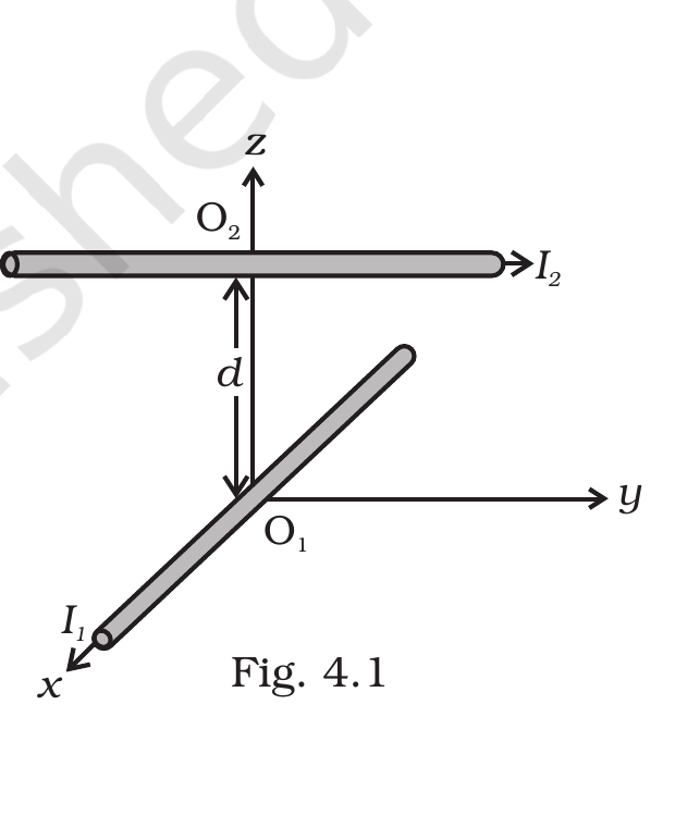
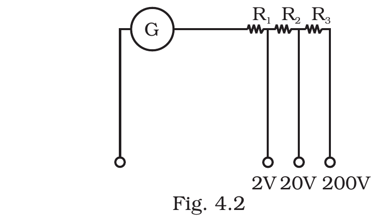
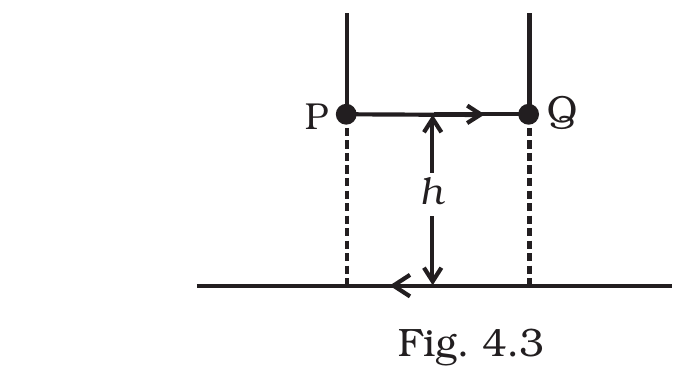
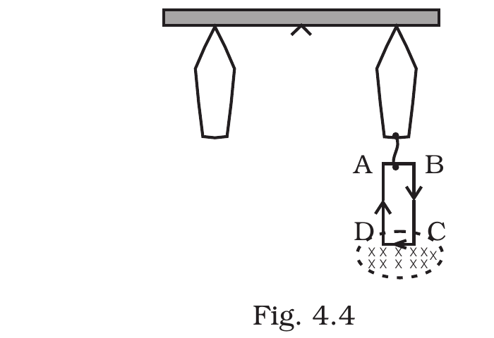
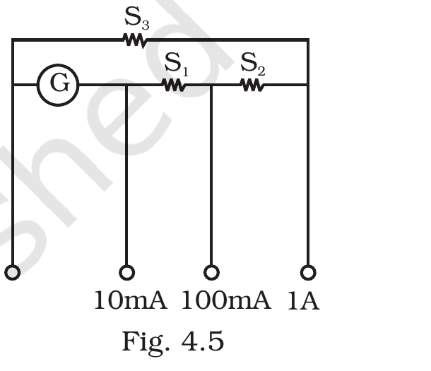
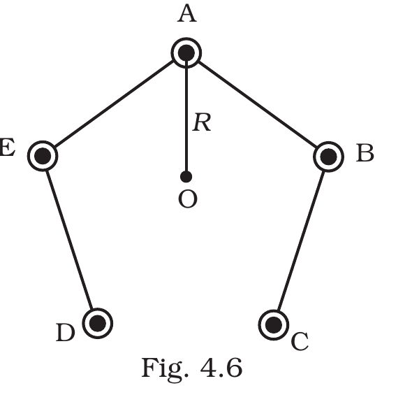


Comments