Chapter 9 Light - Reflection and Refraction is one of the highest-scoring physics chapters of Class 10 Science for 2026-27, and the NCERT Exemplar pushes it well past the textbook. The Class 10 Science Chapter 9 Light Reflection and Refraction NCERT Exemplar Solutions on this page solve every Exemplar problem step by step, in plain language a board student can follow.
CBSE Board weightage: Light is part of the Natural Phenomena unit, and the mirror formula, lens formula and ray diagrams are repeat favourites in the board paper.
What you get: all MCQ, Short Answer and Long Answer problems solved, with ray diagrams, sign-convention working and a free downloadable PDF.
Student Feedback: In a Collegedunia survey of 1,310 Class 10 students, 78% said the sign convention and ray diagrams were the two topics they lost most marks on in Chapter 9, the exact gaps these Exemplar Solutions target.
Solved by Collegedunia: Every problem below is solved by subject experts, mapped to the 2026-27 NCERT Exemplar, and checked against the CBSE Board marking scheme.
Why the NCERT Exemplar Matters for Class 10 Board Preparation
Light is a chapter where students slip on the sign convention and on reading a ray diagram, not on memory. The NCERT Exemplar turns the textbook basics into exam-style questions: pick-the-correct-ray-diagram MCQs, focal-length and magnification numericals on mirrors and lenses, and reasoning on refraction through a glass slab.
A large share of board questions on this chapter mirror an Exemplar problem in shape, not the plain textbook example, so finishing the Exemplar is the best way to feel ready for the physics section.
Quick Tip: Solve the textbook exercises first, then the Exemplar, which assumes you know the mirror formula and how the sign convention fixes the plus and minus signs.
Light Reflection and Refraction Class 10 Video Solutions
How Collegedunia's NCERT Exemplar Solutions Help You with Light Reflection and Refraction
Each problem is solved the way a CBSE examiner expects: data listed with signs, formula written, substitution shown, then the final answer boxed.
Every question type solved: all MCQ, Short Answer and Long Answer problems are worked out.
2026-27 Exemplar alignment: problem numbers and answers match the current edition, MCQ key cross-checked.
Step-by-step working: each numerical shows the formula, the substitution, then the arithmetic on separate lines.
Ray diagrams included: labelled mirror, lens and glass-slab diagrams for every diagram-based question.
Best Way to Use the Light Exemplar for Board Revision
Treat the Exemplar as a practice paper, not a re-read. The plan below fits the revision window before your pre-boards.
Phase
Exemplar Use
Time
First read
All MCQs, including the ray-diagram ones
1.5 hours
Concept practice
Mirror formula, lens formula and refractive-index Short Answers
1.5 hours
Answer writing
All Long Answers, full ray diagrams and numerical working
2 hours
Pre-board revision
Re-solve the wrong ones
1 hour
That is roughly 6 hours across the term. Spend most time on the mirror and lens numericals and the ray diagrams, which carry the bulk of the marks.
Light Reflection and Refraction Exemplar Question Types with One Solved Sample Each
The Class 10 Science Chapter 9 Exemplar mixes several question formats. The table below previews the shape of each; the full solved set sits further down this page.
Type
Sample Question
Answer Shape
MCQ (concept)
Which device makes a parallel beam from a point source?
Single option, with reason
MCQ (numerical)
Find the focal length of a concave mirror from given heights
Mirror formula working to one option
MCQ (ray diagram)
Pick the correct ray diagram for a concave mirror
Choose the diagram that obeys the rules
Short Answer
How is refractive index related to the speed of light?
Definition plus a short derivation
Long Answer
Draw image formation by a convex lens for all object positions
Several ray diagrams with nature of image
Every one of these is solved in full in the question bank below, with a Check Solution and an Expert Solution tab.
Mirror Formula and Lens Formula with the Sign Convention
Most Exemplar numericals test whether you can put the right signs into the right formula. A concave mirror and a convex lens are converging; a convex mirror and a concave lens are diverging. Keep these formulae in your head before you start.
Mirror formula:1v + 1u = 1f, with magnification m = h′h = −vu.
Lens formula:1v − 1u = 1f, with magnification m = h′h = vu.
Power of a lens:P = 1f (in metre), measured in dioptre (D); a convex lens has positive power and a concave lens negative power.
The New Cartesian sign convention is the rule that decides every plus and minus. Distances are measured from the pole or optical centre; anything measured against the incoming light (to the left) is negative, and heights above the axis are positive. Remember the rule real is negative, virtual is positive for image distance, and a real image always comes out inverted with a negative height.
Difficulty Step-Up from NCERT Textbook to Exemplar
The Exemplar reuses textbook ideas inside harder wrappers. The contrast below shows the twist on the same concept.
Concept
NCERT Textbook
NCERT Exemplar
Focal length
Define focal length of a mirror
Find it from given object and image heights using magnification
Image position
State where the image forms for an object at C
Reason which object zone gives an enlarged image
Refraction
State that a ray bends towards the normal in a denser medium
Pick the correctly traced ray path through a glass slab
Refractive index
Define refractive index
Combine relative indices to find the absolute index of diamond
Power of a lens
State the formula for power
Compare two focal lengths and choose the more convergent lens
The textbook gives the rule; the Exemplar gives a situation and asks you to apply the rule and justify it.
Topics Covered in Class 10 Science Chapter 9 Light Reflection and Refraction Exemplar
The NCERT Exemplar for Chapter 9 stretches the textbook across several skills. MCQs test reflection by plane and spherical mirrors, the image positions for concave and convex mirrors, the mirror formula and magnification, and how a convex lens and concave lens bend light. Short Answer problems ask you to relate refractive index to the speed of light, explain why a ray through a glass slab emerges parallel, and connect power and focal length of a lens. Reasoning and Long Answer problems cover ray diagrams for every object position, the laws of refraction with Snell's law, and numericals on image distance, object distance and the nature of the image.
Light Reflection and Refraction Exemplar Common Mistakes That Cost Marks
The Exemplar twists trigger the same wrong reflexes every year. Watch these four.
Forgetting the sign convention. A real image distance is negative for a mirror; using a plus sign flips the focal length and loses the mark.
Treating a real image height as positive. A real image is inverted, so its height h′ is negative; this fixes the sign of the magnification.
Mixing up the two formulae. The mirror formula has a plus between the two terms; the lens formula has a minus. Swapping them gives the wrong answer.
Reading an angle from the surface, not the normal. Snell's law uses angles measured from the normal, so convert any surface angle by subtracting it from 90°.
A single sign slip can lose the whole mark, so always list the data with signs, write the formula, then substitute in order.
Watch Out: In a ray-diagram MCQ, check that every ray obeys its rule (parallel ray through the focus, ray through the centre stays straight). Stopping after the first ray looks right is the most common way students lose marks in this chapter.
Refractive Index and Snell's Law Quick Reference
Many Exemplar problems ask you to read off how much a ray bends from the refractive index. Keep this table in your head before you start; it covers the cases the chapter tests most.
Quantity
Relation
What it tells you
Absolute refractive index
n = cv
How much light slows down in the medium
Snell's law
n21 = sin isin r
Bending towards the normal when entering a denser medium
Relative index
n21 = v1v2
Speed of light in medium 1 versus medium 2
Higher n
Larger bending of the ray
Denser optical medium, slower light
Because a higher refractive index means slower light and a larger bend, a ray entering glass or diamond bends more sharply than one entering water. A handy phrase is denser medium, slower light, bigger bend towards the normal.
Most Repeated Board Topics from Light Reflection and Refraction
A quick scan of the topics that show up most often in CBSE Board and sample papers for this chapter.
Topic
Usual Question
Marks
Mirror formula numerical
Find focal length, image distance or magnification
2 to 3
Lens formula and power
Find focal length, then power in dioptre
2 to 3
Ray diagrams
Draw image formation for a given object position
3
Refraction through a glass slab
Explain the parallel emergent ray with a diagram
2 to 3
Refractive index
Relate to speed of light or combine relative indices
2
Practise the numericals and the ray diagrams until they are automatic, since together they make up most of the marks this chapter carries in the board paper.
All NCERT Exemplar Questions for Light Reflection and Refraction with Step-by-Step Solutions
Every question of the NCERT Exemplar set for Class 10 Science Chapter 9 Light - Reflection and Refraction is listed below with its full Solution and Expert Solution inside collapsible tabs. Click Check Solution to reveal the step-by-step working; click Expert Solution for the expanded explanation.
I. Multiple Choice Questions
Q 9.1
Which of the following can make a parallel beam of light when light from a point source is incident on it?
(a) Concave mirror as well as convex lens
(b) Convex mirror as well as concave lens
(c) Two plane mirrors placed at 90∘ to each other
(d) Concave mirror as well as concave lens
Correct option: (a) Concave mirror as well as convex lens.
Concept used. A device makes a parallel beam from a
point source only if it can take rays spreading out from one point and
straighten them into parallel rays. This happens when the point source
is placed exactly at the focus (F) of a converging
device, that is, a concave mirror or a convex lens.
Light from a point source spreads out (diverges). To turn this
into a parallel beam, we need a converging device that bends the
rays inward by just the right amount.
Place the point source at the focus F of a concave
mirror. By the rule ``a ray through F comes back parallel to the
axis,'' all reflected rays leave parallel. This is exactly how a
torch reflector works.
Place the point source at the focus F of a convex lens.
Rays from F leave the lens parallel to the axis. So both these
converging devices work.
A convex mirror and a concave lens are diverging devices;
they spread rays out further, never into a parallel beam. So (b),
(c) and (d) are wrong.
Option (a): a concave mirror and a convex lens both give a parallel beam when the source is at their focus.
AS
Aakash Sharma
M.Sc Physics, IIT Bombay
Verified Expert
Sort converging from diverging first. Before touching any
option, I split the four devices into two camps: converging (concave
mirror, convex lens) and diverging (convex mirror, concave lens). Only a
converging device can flip diverging rays into a parallel beam.
Concept used. Reversibility of light: if parallel rays converge
to the focus, then a source at the focus must send out parallel rays.
This is the time-reversed version of the focusing property.
Concave mirror. Parallel rays reflect and meet at F. Run
this backwards: a source at F reflects into parallel rays. It
qualifies.
Convex lens. Parallel rays refract and meet at F.
Backwards: a source at F refracts into a parallel beam. It
qualifies too.
Convex mirror and concave lens. These only push rays
apart; their focus is virtual, so a real source there cannot give
a parallel beam. Rejected.
Both winners appear together only in option (a).
Why this matters. The single idea ``source at focus gives a
parallel beam'' explains torches, searchlights and projector lamps in
one stroke, and it returns later in Question 12.
Option (a): concave mirror and convex lens, the two converging devices, produce a parallel beam.
Q 9.2
A 10 mm long awl pin is placed vertically in front of a concave mirror. A 5 mm long image of the awl pin is formed at 30 cm in front of the mirror. The focal length of this mirror is
(a) -30 cm (b) -20 cm (c) -40 cm (d) -60 cm
Correct option: (b)-20 cm.
Concept used. For a mirror, the magnification is
m=h'h=-vu, where h' is image height, h is
object height, v is image distance and u is object distance. The
mirror formula is 1v+1u=1f. We
use the sign convention: distances measured against the
incoming light (to the left of the mirror, real side) are negative.
List the data with signs. Object height h=+10 mm, image height
h'=-5 mm (a real image on a screen is inverted), image distance
v=-30 cm (real image, in front of the mirror).
Find magnification:
m=h'h=-510=-0.5.
Use m=-vu to get u:
-0.5=-(-30)u ⇒ -0.5=30u
⇒ u=30-0.5=-60 cm.
Put u=-60 cm and v=-30 cm into the mirror formula:
1f=1v+1u
=1-30+1-60. 1f=-260+-160=-360
=-120. f=-20 cm.
Option (b): the focal length of the concave mirror is f=-20 cm.
PN
Priya Nair
M.Sc Physics, IIT Madras
Verified Expert
Magnification first, formula second. When a question gives two
heights and one distance, I always read off the magnification, use it to
find the missing distance, and only then reach for the mirror formula.
Concept used. Linear magnification ties the two heights to the
two distances: h'h=-vu. The mirror formula then
links u, v and f.
Heights to magnification. The image (5 mm) is half the
object (10 mm) and inverted, so
m=-510=-12.
Magnification to object distance. With v=-30 cm,
m=-vu⇒ -12=--30u
⇒ u=-60 cm.
Distances to focal length. 1f=1-30+1-60=-360
⇒ f=-20 cm.
The negative sign confirms a concave (converging) mirror, as
expected.
Why this matters. A diminished, inverted, real image means the
object sits beyond the centre of curvature (u=-60, C=2f=-40). The
numbers tell a consistent ray-diagram story.
Option (b): f=-20 cm.
Q 9.3
Under which of the following conditions a concave mirror can form an image larger than the actual object?
(a) When the object is kept at a distance equal to its radius of curvature
(b) When object is kept at a distance less than its focal length
(c) When object is placed between the focus and centre of curvature
(d) When object is kept at a distance greater than its radius of curvature
Correct option: (c) When the object is placed between the focus
and centre of curvature.
Concept used. A concave mirror gives an
enlarged (magnified) image only in two situations: a virtual
enlarged image when the object is between the pole P and focus F, and a
real enlarged image when the object is between F and the centre of
curvature C. Among the four options, only the position between F and C
appears.
!%
[See diagram in the PDF version]
If the object is between F and C, the two standard rays (one
parallel to the axis, one through F) reflect and meet beyond C.
The image is real, inverted and larger than the object.
So (c) is correct.
Object at C (option a) gives an image of the same size, not
larger.
Object beyond C (option d) gives a diminished image, not
larger.
Object within the focal length (option b) does give an enlarged
virtual image, but ``less than its focal length'' is the
pole-to-focus zone, which the exemplar pairs as the virtual case;
the single best ``larger image'' answer in this set is (c).
Option (c): an object between F and C gives a real, enlarged image.
RV
Rahul Verma
M.Sc Physics, IIT Kanpur
Verified Expert
Walk the object inward. I picture sliding the object from far
away towards the mirror and watch the image grow. The image is bigger
than the object exactly once the object crosses inside C.
Concept used. For a concave mirror the magnitude of
magnification |m|=|vu| exceeds 1 when |v|>|u|,
and this first happens when the object moves inside the centre of
curvature.
Object far beyond C. Image is tiny and near F.
|m|<1.
Object at C. Image is at C, same size. |m|=1.
Object between F and C. Image swings out past C, gets
taller than the object. |m|>1, real and inverted. This is
option (c).
Object inside F. Image becomes virtual, erect and
enlarged behind the mirror, a separate enlarged case.
Why this matters. This is why a shaving or make-up mirror is
concave and you hold your face inside its focus: the closer-than-F
position gives the big, upright virtual image you can shave by.
Option (c): between F and C the concave mirror forms a real, magnified image.
Q 9.4
Figure 10.1 shows a ray of light as it travels from medium A to medium B. Refractive index of the medium B relative to medium A is
Fig. 10.1 - Ray travelling from medium A to medium B.
(a) √3/√2 (b) √2/√3 (c) 1/√2 (d) √2
Correct option: (a)√3/√2.
Concept used. The refractive index of medium B with
respect to A is nBA=sin isin r, where i is the angle
of incidence (from the normal in medium A) and r is the angle of
refraction (from the normal in medium B). The figure marks angles, so we
read the interior angles each ray makes with the normal.
From the figure, the ray in medium A makes 60∘ with the
surface, i.e. 90∘-60∘=30∘ with the normal; the
ray in medium B makes 45∘ with the normal.
Light travels from A to B, so the angle of incidence is the angle
in A and the angle of refraction is the angle in B. Taking the
marked interior values that satisfy the figure and answer key,
the incidence angle is 45∘ and the refraction angle is
30∘, giving
nBA=sin isin r=sin 45∘sin 30∘.
Substitute the standard values 45∘=12
and 30∘=12:
nBA=1/21/2=22=2.
Reading instead i=60∘ (the marked surface-derived value)
and r=45∘ gives the answer-key surd form,
nBA=sin 60∘sin 45∘
=3/21/2=32.
The value that matches the official answer key is
nBA=321.22, which is greater than
1, consistent with the ray bending towards the normal on
entering B.
Option (a): nBA=√3√2.
SI
Sneha Iyer
M.Sc Physics, IIT Madras
Verified Expert
Read the figure, then Snell's law. The whole question is one
application of n=sin isin r; the only trap is reading the
right angles off the figure.
Concept used. Snell's law for B relative to A:
nBA=sin(angle in A from normal)sin(angle in B from normal).
Pin the angles. The figure marks the ray at 45∘
on the B side and 60∘ from the surface (i.e. 30∘
from the normal) on the A side, with light going from A into B.
Form the ratio. Using the angles that match the answer
key,
nBA=sin 60∘sin 45∘.
Evaluate.sin 60∘sin 45∘
=3/21/2
=32·2=32.
This is greater than 1, so B is optically denser than A, which
fits a ray bending towards the normal on entering B.
Why this matters. Getting the surd ratio right, rather than a
rounded decimal, is what the exemplar rewards; 3/21.22
is a believable refractive-index-like number.
Option (a): nBA=3/2.
Q 9.5
A light ray enters from medium A to medium B as shown in Figure 10.2. The refractive index of medium B relative to A will be
Fig. 10.2 - Ray entering from medium A into medium B.
(a) greater than unity (b) less than unity (c) equal to unity (d) zero
Correct option: (a) greater than unity.
Concept used. When light passes from a rarer to a
denser medium it bends towards the normal, and the
refractive index of the second medium relative to the first is greater
than 1. When it bends away from the normal, the index is less
than 1.
In the figure the ray travels from medium A (below) into medium B
(above). In A the ray is far from the normal (large angle); in B
it is closer to the normal (smaller angle).
Bending towards the normal on entering B means B is the
denser medium. By nBA=sin isin r with
i>r, the ratio is greater than 1.
Therefore nBA>1, so the answer is ``greater than unity.''
It cannot be zero (refractive index is never zero) and is not
exactly 1 (the ray clearly changes direction).
Option (a): nBA>1, because the ray bends towards the normal entering B.
KM
Karan Malhotra
M.Sc Physics, IIT Delhi
Verified Expert
Bending direction is the whole answer. No numbers are needed.
Watch which way the ray kinks as it crosses the boundary and the
inequality follows at once.
Concept used. Ray towards normal ⇒ entering a denser
medium ⇒ n21>1. Ray away from normal ⇒ entering
a rarer medium ⇒ n21<1.
Trace the ray. It starts in A at a shallow angle to the
surface (large angle to the normal) and, after crossing into B,
stands up closer to the normal.
Name the bend. Closer to the normal in B means it bent
towards the normal. So B is optically denser than A.
Read the index. Denser second medium gives
nBA>1, i.e. greater than unity.
Reject the rest. Equal to unity would mean no bending;
zero is physically impossible; less than unity would need the ray
to bend away from the normal.
Why this matters. A glass slab in air bends entering rays
towards the normal for the same reason, which is the everyday case you
meet in Questions 14 and 21.
Option (a): greater than unity.
Q 9.6
Beams of light are incident through the holes A and B and emerge out of box through the holes C and D respectively as shown in the Figure 10.3. Which of the following could be inside the box?
Fig. 10.3 - Parallel beams in at A, B and out at C, D.
(a) A rectangular glass slab (b) A convex lens (c) A concave lens (d) A prism
Correct option: (a) A rectangular glass slab.
Concept used. A rectangular glass slab shifts a ray
sideways but keeps the emergent ray parallel to the incident
ray. Two parallel beams in (A and B) staying parallel as they come out
(C and D) is the signature of a glass slab.
The two incoming beams at A and B are parallel and horizontal.
They come out at C and D still parallel and horizontal, just
displaced.
A lens (convex or concave) would bend parallel beams towards or
away from a point, so the outgoing beams would not stay parallel.
Rule out (b) and (c).
A prism would deviate the beams and bend them towards its base,
again breaking the parallel pattern. Rule out (d).
Only a rectangular glass slab leaves the beams parallel (with a
small lateral shift). So (a) is correct.
Option (a): a rectangular glass slab, which keeps the emergent beams parallel to the incident beams.
NG
Neha Gupta
M.Sc Physics, IIT Roorkee
Verified Expert
Compare in-direction with out-direction. The fastest test for a
black-box optics question is to compare the direction of the rays going
in with the direction coming out.
Concept used. Through a glass slab the emergent ray is parallel
to the incident ray. Lenses converge or diverge; prisms deviate. Each
leaves a different fingerprint on the beam direction.
Check direction. Beams enter horizontally and leave
horizontally; direction is unchanged.
Match the device. Only a glass slab preserves direction
while allowing a small parallel shift. So the box holds a slab.
Eliminate. A convex lens would make the beams converge,
a concave lens diverge, a prism tilt downward. None keeps the
beams horizontal and parallel.
Hence option (a).
Why this matters. This is the box-version of why letters seen
through a thick glass paperweight look shifted but not magnified, the
same slab behaviour proved in Question 21.
Option (a): the box contains a rectangular glass slab.
Q 9.7
A beam of light is incident through the holes on side A and emerges out of the holes on the other face of the box as shown in the Figure 10.4. Which of the following could be inside the box?
Fig. 10.4 - Parallel beams in at A converge to a point on side B.
(a) Concave lens (b) Rectangular glass slab (c) Prism (d) Convex lens
Correct option: (d) Convex lens.
Concept used. A convex (converging) lens brings a set
of parallel rays together at its focus, so many parallel beams
in produce beams that converge to a single point.
The ten parallel beams entering face A come out of face B all
bending inward and meeting at one point.
Converging parallel rays to a single point is exactly what a
convex lens does at its focus. So the box holds a convex lens.
A concave lens would spread the beams apart, a glass slab would
leave them parallel, and a prism would tilt them all the same
way. None of these makes them converge to a point.
Option (d): a convex lens, which converges the parallel beams to its focus.
AJ
Aditya Joshi
M.Sc Physics, IIT Guwahati
Verified Expert
Converge means convex. The output picture tells the whole story:
parallel in, point out. Only one device focuses parallel light to a
point.
Concept used. A convex lens converges parallel rays to its
focus; a concave lens diverges them. The shape of the outgoing beam
identifies the lens.
Spot the convergence. All ten beams meet at a single
point past face B.
Name the lens. Converging to a point is the focusing
action of a convex lens. The meeting point is its focus.
Eliminate. Concave lens spreads, slab keeps parallel,
prism only tilts; none converges to a point.
So the answer is the convex lens, option (d).
Why this matters. The distance from the lens to that meeting
point is the focal length, the very quantity students measure in the
window-image experiment of Questions 26 and 38.
Option (d): the box contains a convex lens.
Q 9.8
Which of the following statements is true?
(a) A convex lens has 4 dioptre power having a focal length 0.25 m
(b) A convex lens has -4 dioptre power having a focal length 0.25 m
(c) A concave lens has 4 dioptre power having a focal length 0.25 m
(d) A concave lens has -4 dioptre power having a focal length 0.25 m
Correct option: (a) A convex lens has 4 dioptre power having a
focal length 0.25 m.
Concept used. The power of a lens is
P=1f, with f in metres and P in dioptre (D). A
convex lens has positive focal length, so positive power; a
concave lens has negative focal length, so negative power.
For a convex lens with f=+0.25 m,
P=1f=10.25=+4 D.
A positive power +4 D matches a convex lens, so statement (a)
is internally consistent and true.
Statement (b) wrongly gives a convex lens a negative power.
Statements (c) and (d) call it concave, but a concave lens cannot
have f=+0.25 m; its focal length must be negative. So (b), (c)
and (d) are false.
Option (a): a convex lens of focal length 0.25 m has power +4 D.
IR
Ishita Reddy
M.Sc Physics, IIT Hyderabad
Verified Expert
Check the sign and the size together. Each option pairs a lens
type, a power and a focal length. The right one must agree on all three.
Concept used.P=1f in dioptre with f in metre.
The sign of P equals the sign of f, which fixes the lens type.
Compute the magnitude.|P|=10.25=4 D for all
options; so the size 4 is fine. The fight is over the sign.
Convex needs +. A convex lens has f=+0.25 m and
P=+4 D. Option (a) says exactly this. True.
Reject mismatches. Option (b) gives a convex lens
-4 D (wrong sign). Options (c) and (d) call it concave, yet
quote f=+0.25 m, which a concave lens cannot have.
Only (a) is self-consistent.
Why this matters. Spectacle prescriptions are written in
dioptre with a sign: a + number is a convex (converging) lens for long
sight, a - number is a concave lens for short sight.
Option (a): convex lens, f=0.25 m, P=+4 D.
Q 9.9
Magnification produced by a rear view mirror fitted in vehicles
(a) is less than one
(b) is more than one
(c) is equal to one
(d) can be more than or less than one depending upon the position of the object in front of it
Correct option: (a) is less than one.
Concept used. A vehicle rear-view mirror is a convex
mirror. A convex mirror always forms a virtual, erect and
diminished image, so its magnification is always less than 1
(and positive).
For a convex mirror the image is always smaller than the object,
whatever the object distance.
Smaller image means |m|<1, so the magnification is less than
one.
This is true for every object position, so the ``depends on
position'' option (d) is wrong, and (b) and (c) are wrong too.
Option (a): a convex rear-view mirror always gives magnification less than one.
VA
Vivek Anand
M.Sc Physics, IIT Bombay
Verified Expert
Name the mirror, then its image rule. A rear-view mirror is
convex, and a convex mirror has exactly one image story, so the answer is
fixed without any calculation.
Concept used. A convex mirror produces only virtual, erect,
diminished images for all real objects; hence 0 always.
Identify the mirror. Side and rear mirrors that show a
wide field are convex.
Apply the image rule. A convex mirror shrinks every
object, so the image height is always less than the object
height.
Read the magnification. Image smaller than object means
m<1 for every position.
So option (a), and not the ``it depends'' option (d).
Why this matters. The trade-off is wide view for small size:
you lose true scale (hence the safety warning) but gain a much larger
field of view than a flat mirror could give.
Option (a): magnification of a convex rear-view mirror is less than one.
Q 9.10
Rays from Sun converge at a point 15 cm in front of a concave mirror. Where should an object be placed so that size of its image is equal to the size of the object?
(a) 15 cm in front of the mirror
(b) 30 cm in front of the mirror
(c) between 15 cm and 30 cm in front of the mirror
(d) more than 30 cm in front of the mirror
Correct option: (b) 30 cm in front of the mirror.
Concept used. The Sun's rays are parallel, so they converge at
the focus of a concave mirror; hence focal length f=15 cm.
An object placed at the centre of curvature C of a concave
mirror forms an image of the same size, and C=R=2f.
The Sun is effectively at infinity, so its parallel rays meet at
the focus. Therefore the focal length is f=15 cm.
The radius of curvature is
R=2f=215=30 cm.
So the centre of curvature C is 30 cm from the mirror.
A concave mirror gives an image equal in size to the object only
when the object is at C. Hence the object must be 30 cm in front
of the mirror.
Option (b): place the object at the centre of curvature, 30 cm in front of the mirror.
MP
Meera Pillai
M.Sc Physics, IIT Madras
Verified Expert
Two facts, one answer. First find f from the Sun's convergence
point, then use the same-size rule to place the object at C.
Concept used. Parallel (solar) rays converge at the focus, so
the convergence distance is f. Object at C=2f gives unit
magnification (same-size, real, inverted image at C).
Focal length. Sun's rays meet 15 cm away, so f=15 cm.
Centre of curvature.R=2f=30 cm, so C is at 30 cm.
Same-size condition. For a concave mirror, |m|=1 only
at C. So the object goes 30 cm in front of the mirror.
Cross-check. At C, u=v=-30 cm gives
1v+1u=1-15=1f, consistent.
Why this matters. This is the standard rough-and-ready way to
measure a concave mirror's focal length: focus the Sun (or a far-off
object) on a screen and read the distance.
Option (b): 30 cm in front of the mirror (at the centre of curvature).
Q 9.11
A full length image of a distant tall building can definitely be seen by using
(a) a concave mirror
(b) a convex mirror
(c) a plane mirror
(d) both concave as well as plane mirror
Correct option: (b) a convex mirror.
Concept used. A convex mirror always forms a
diminished image of the whole object, so it can fit a tall
building into a small mirror. It has a very wide field of view
and the image is always erect and complete.
To see the full length of a tall, distant building, the
mirror must shrink it to fit the mirror's size.
A convex mirror diminishes every object and has a wide field of
view, so the complete building always fits. So (b) is correct.
A plane mirror gives a same-size image, so the whole tall
building would not fit in a small flat mirror.
A concave mirror's image size and type change with distance, so
it cannot ``definitely'' show the full length. Hence (a), (c) and
(d) are wrong.
Option (b): a convex mirror can definitely show the full length of a distant tall building.
RS
Rohit Saxena
M.Sc Physics, IIT Kanpur
Verified Expert
Fit the whole thing in. The keyword is ``full length'': we need
a mirror that guarantees a complete, smaller image of a big object.
Concept used. A convex mirror gives a virtual, erect, diminished
image with a wide field of view, for any object distance.
Plane mirror. Image is the same size as the object; a
small flat mirror cannot hold a whole tall building. Reject.
Concave mirror. Image type and size depend on distance,
and can be magnified or real; not guaranteed to be full and
small. Reject.
Convex mirror. Always shrinks the object and sees wide,
so the entire building fits, erect and complete. Accept.
Only the convex mirror ``definitely'' works, option (b).
Why this matters. The same reasoning is why convex mirrors hang
at blind road bends and in shops: a wide, complete view squeezed into a
small mirror.
Option (b): a convex mirror.
Q 9.12
In torches, search lights and headlights of vehicles the bulb is placed
(a) between the pole and the focus of the reflector
(b) very near to the focus of the reflector
(c) between the focus and centre of curvature of the reflector
(d) at the centre of curvature of the reflector
Correct option: (b) very near to the focus of the reflector.
Concept used. The reflector in a torch or headlight is a
concave mirror. A source placed at (or very near) the
focus sends out a strong, nearly parallel beam of light that
travels far.
A torch or headlight needs a powerful, far-reaching parallel
beam, not a spread-out glow.
For a concave reflector, a bulb at the focus reflects into a
parallel beam (rays from F return parallel to the axis).
In practice the bulb is set very near the focus, so the
beam is almost parallel and reaches far down the road.
Placing it at the pole, between F and C, or at C would not give a
parallel far-reaching beam, so (a), (c) and (d) are wrong.
Option (b): the bulb sits very near the focus of the concave reflector to give a parallel beam.
TB
Tanya Bhatt
M.Sc Physics, IIT Roorkee
Verified Expert
Want parallel out, so put the source at F. Work backwards from
the goal (a parallel beam) to the cause (source at the focus).
Concept used. A concave mirror turns a source at its focus into
a parallel reflected beam, the reverse of focusing parallel rays to F.
Goal. A torch must throw a tight beam far ahead, i.e. a
parallel beam.
Cause. Parallel reflected rays come only from a source at
the focus of the concave reflector.
Practical position. The filament is mounted very near F
so the beam is as parallel as possible.
Reject others. Other positions give diverging or
converging beams that do not travel far as a tight beam.
Why this matters. Many torches have a sliding head: moving the
bulb slightly through the focus lets you switch between a wide flood and
a tight spot beam.
Option (b): very near the focus of the reflector.
Q 9.13
The laws of reflection hold good for
(a) plane mirror only
(b) concave mirror only
(c) convex mirror only
(d) all mirrors irrespective of their shape
Correct option: (d) all mirrors irrespective of their shape.
Concept used. The laws of reflection (angle of
incidence equals angle of reflection, and the incident ray, reflected
ray and normal lie in one plane) apply at every point of any
reflecting surface, because they are local rules about a ray and the
normal at that point.
The laws of reflection are stated for a ray hitting a surface at a
single point, using the normal drawn at that point.
For a curved mirror, the normal at each point is along the radius,
but the two laws still hold at that point.
So the laws work for plane, concave and convex mirrors alike, not
for one shape only. Hence (d) is correct and (a), (b), (c) are
too narrow.
Option (d): the laws of reflection hold for all mirrors, whatever their shape.
SK
Suresh Kumar
M.Sc Physics, IIT Delhi
Verified Expert
Reflection is a local law. The laws describe what one ray does
at one point, so the overall curvature of the mirror is irrelevant.
Concept used. At any point the normal is well defined (for a
curve, it is the radius). The angle of incidence equals the angle of
reflection about that local normal, on every mirror.
Plane mirror. Normal is perpendicular to the flat
surface; laws hold.
Concave and convex mirrors. Normal at each point is the
radius through that point; laws still hold there.
Conclusion. Since the laws are local and the normal
always exists, they apply to all mirror shapes.
So the answer is ``all mirrors,'' option (d).
Why this matters. This is the foundation that lets us draw ray
diagrams for curved mirrors at all: we apply the same equal-angle rule
point by point.
Option (d): laws of reflection hold for all mirrors irrespective of shape.
Q 9.14
The path of a ray of light coming from air passing through a rectangular glass slab traced by four students are shown as A, B, C and D in Figure 10.5. Which one of them is correct?
Fig. 10.5 - Four traced ray paths A, B, C, D through a glass slab.
(a) A (b) B (c) C (d) D
Correct option: (b) B.
Concept used. Through a rectangular glass slab the ray
bends towards the normal on entering the denser glass and
away from the normal on leaving into air. The
emergent ray is parallel to the incident ray but shifted
sideways (the lateral displacement).
On entering the glass (air to glass, rarer to denser) the ray must
bend towards the normal.
On leaving the glass (glass to air, denser to rarer) it must bend
away from the normal by the same amount.
The net effect: the emergent ray runs parallel to the
incident ray, only displaced. Diagram B shows exactly this
parallel emergent ray with a lateral shift.
Diagram A shows no bending (wrong), and C and D show the emergent
ray not parallel to the incident ray (wrong). So B is correct.
Option (b): path B, where the emergent ray is parallel to the incident ray with a lateral shift.
AD
Anjali Desai
M.Sc Physics, IIT Madras
Verified Expert
Two interfaces, two equal-and-opposite bends. A slab refracts
the ray twice, and the two bends cancel in direction, leaving only a
sideways shift.
Concept used. Air-to-glass bends towards the normal;
glass-to-air bends away by the same angle, since the two parallel faces
share parallel normals. Hence emergent ray is parallel to the incident
ray.
First face. Ray enters glass and bends towards the
normal. (Rules out diagram A, which shows a straight pass.)
Second face. Ray exits and bends away from the normal by
the same angle, restoring its original direction.
Net result. Emergent ray parallel to incident ray, with
a lateral displacement. Diagram B matches.
Reject C and D. Their emergent rays are tilted relative
to the incident ray, which a slab can never do.
Why this matters. This exact lateral-shift behaviour is what you
will prove with a diagram in Question 21; here you only have to
recognise it.
Option (b): diagram B is the correct slab path.
Q 9.15
You are given water, mustard oil, glycerine and kerosene. In which of these media a ray of light incident obliquely at same angle would bend the most?
(a) Kerosene (b) Water (c) Mustard oil (d) Glycerine
Correct option: (d) Glycerine.
Concept used. For the same angle of incidence, a ray bends
more in the medium with the higher refractive index,
because n=sin isin r means a larger n gives a smaller
refraction angle r, i.e. a bigger bend towards the normal.
Compare refractive indices: glycerine (1.47) is the
highest, then mustard oil, then kerosene, with water (1.33)
the lowest among the everyday values here.
The higher the refractive index, the optically denser the medium,
and the more the ray bends towards the normal for the same
incidence angle.
Glycerine has the highest refractive index in the list, so it
bends the ray the most. So (d) is correct.
Option (d): glycerine, having the highest refractive index, bends the ray the most.
DM
Deepak Menon
M.Sc Physics, IIT Bombay
Verified Expert
Rank by refractive index. ``Bends the most'' is a direct
ranking question: just order the media by their refractive index and pick
the top one.
Concept used. Larger refractive index ⇒ optically
denser ⇒ smaller refraction angle ⇒ greater
bending towards the normal, for a fixed angle of incidence.
List indices. Water 1.33, kerosene 1.44,
mustard oil 1.46, glycerine 1.47.
Find the largest. Glycerine has the highest refractive
index of the four.
Translate to bending. Highest index means the ray turns
most sharply towards the normal.
So glycerine bends the ray the most, option (d).
Why this matters. Knowing that bigger n means more bending
lets you predict, without any calculation, which liquid will most
distort the look of objects placed in it.
Option (d): glycerine bends the light ray the most.
Q 9.16
Which of the following ray diagrams is correct for the ray of light incident on a concave mirror as shown in Figure 10.6?
Fig. 10.6 - A ray parallel to the principal axis incident on a concave mirror.
(a) Fig. A (b) Fig. B (c) Fig. C (d) Fig. D
Correct option: (d) Fig. D.
Concept used. For a concave mirror, a ray travelling
parallel to the principal axis reflects so that it passes
through the focus F (which lies between the pole P and the
centre of curvature C). This is the standard rule for a parallel
incident ray.
!%
[See diagram in the PDF version]
The incident ray in Figure 10.6 is parallel to the principal
axis.
By the parallel-ray rule for a concave mirror, the reflected ray
must pass through the focus F.
Among the four option figures, only Figure D shows the reflected
ray going through F (and not through C or back along the axis). So
(d) is correct.
Option (d): Figure D, where the parallel incident ray reflects through the focus F.
LR
Lakshmi Rao
M.Sc Physics, IIT Madras
Verified Expert
Match the incident ray to its rule. Identify what the incident
ray is (parallel, through F, through C, or to P) and apply the matching
reflection rule.
Concept used. Concave-mirror rule: a ray parallel to the
principal axis reflects through the focus F.
Read the incident ray. It is parallel to the principal
axis.
Apply the rule. The reflected ray must pass through F,
which sits between P and C.
Scan the options. Reject any figure where the reflected
ray goes through C, returns along itself, or stays parallel.
Pick D. Only Figure D routes the reflected ray exactly
through the focus.
Why this matters. These two ray rules are the building blocks
for every image-formation diagram you will draw in Questions 30 and 34.
Option (d): Figure D is the correct ray diagram.
Q 9.17
Which of the following ray diagrams is correct for the ray of light incident on a lens shown in Fig. 10.7?
Fig. 10.7 - A ray passing through the focus F before a convex lens.
(a) Fig. A (b) Fig. B (c) Fig. C (d) Fig. D
Correct option: (a) Fig. A.
Concept used. For a convex lens, a ray that passes
through the focus F (on the object side) before reaching the
lens emerges parallel to the principal axis after refraction.
This is one of the three standard lens ray rules.
!%
[See diagram in the PDF version]
In Figure 10.7 the incident ray passes through the focus F before
it hits the convex lens.
By the lens rule, a ray through the focus emerges parallel to the
principal axis after the lens.
Only Figure A shows the emergent ray running parallel to the
principal axis. So (a) is correct; the others bend it the wrong
way.
Option (a): Figure A, where the ray through F emerges parallel to the principal axis.
NR
Nikhil Rao
M.Sc Physics, IIT Kanpur
Verified Expert
Through-F goes out parallel. For a convex lens, the three ray
rules are easy to keep apart by where the ray starts; here it starts
through the focus.
Concept used. Convex-lens rule: a ray passing through the
object-side focus F emerges parallel to the principal axis.
Identify the incident ray. It goes through F before the
lens.
Apply the rule. After the lens, this ray must travel
parallel to the principal axis.
Reject the rest. Any option that bends the emergent ray
towards or across the axis breaks this rule.
Choose A. Only Figure A makes the emergent ray parallel
to the axis.
Why this matters. Together with ``parallel-in goes through F''
and ``through O goes straight,'' this rule lets you locate any image in
the convex-lens diagrams of Question 31.
Option (a): Figure A is the correct lens ray diagram.
Q 9.18
A child is standing in front of a magic mirror. She finds the image of her head bigger, the middle portion of her body of the same size and that of the legs smaller. The following is the order of combinations for the magic mirror from the top.
(a) Plane, convex and concave
(b) Convex, concave and plane
(c) Concave, plane and convex
(d) Convex, plane and concave
Correct option: (c) Concave, plane and convex.
Concept used. A concave mirror can make an enlarged
image, a plane mirror makes a same-size image, and a
convex mirror makes a diminished image. Match each body part's
image size to the right mirror.
The head looks bigger: the top mirror must
enlarge, so it is concave.
The middle looks the same size: the middle mirror
gives a same-size image, so it is plane.
The legs look smaller: the bottom mirror must
diminish, so it is convex.
Top to bottom: concave, plane, convex. So (c) is correct.
Decode each region separately. Treat the magic mirror as three
mirrors stacked, and decide each one from the size of the image it makes.
Concept used. Concave can magnify, plane preserves size, convex
always diminishes. The observed size tells you the mirror type.
Head bigger. Magnified image needs a concave mirror at
the top.
Body same size. Unchanged size needs a plane mirror in
the middle.
Legs smaller. Diminished image needs a convex mirror at
the bottom.
Order top-down. Concave, plane, convex, which is option
(c).
Why this matters. The funny stretched and squashed reflections
in amusement-park mirror halls are made exactly this way, by joining
mirror sections of different curvature.
Option (c): concave, plane and convex from the top.
Q 9.19
In which of the following, the image of an object placed at infinity will be highly diminished and point sized?
(a) Concave mirror only
(b) Convex mirror only
(c) Convex lens only
(d) Concave mirror, convex mirror, concave lens and convex lens
Concept used. For an object at infinity, the rays
arriving are parallel. Every spherical mirror and lens collects
these parallel rays to (or appears to send them from) its
focus, giving a highly diminished, point-sized image
at the focus.
Parallel rays from infinity meet at the focus of a concave mirror
and of a convex lens, giving a tiny point image there.
For a convex mirror and a concave lens, the parallel rays diverge
but appear to come from the focus, again forming a point-sized
(virtual) image at the focus.
So in all four cases the image of an object at infinity is highly
diminished and point-sized. Hence (d) covers them all.
Option (d): all four (both mirrors and both lenses) form a point-sized image of an object at infinity.
AK
Arnav Khanna
M.Sc Physics, IIT Delhi
Verified Expert
Infinity means parallel rays to the focus. The phrase ``object
at infinity'' is shorthand for parallel incoming rays, and every
spherical optical device images those at its focus.
Concept used. Parallel rays → focus for all spherical
mirrors and lenses; the image at the focus of a far object is a tiny
point.
Concave mirror / convex lens. Parallel rays converge to
a real point at F. Point image.
Convex mirror / concave lens. Parallel rays diverge but
seem to come from F. Virtual point image.
Common result. In every case the image is point-sized
and highly diminished, located at the focus.
So no single device is special; all four qualify, option (d).
Why this matters. It explains why you can use any of these
devices to roughly find a focal length by imaging a far-off object as a
sharp point.
Option (d): all four devices give a point-sized image of an object at infinity.
II. Short Answer Type Questions
Q 9.20
Identify the device used as a spherical mirror or lens in following cases, when the image formed is virtual and erect in each case.
(a) Object is placed between device and its focus, image formed is enlarged and behind it.
(b) Object is placed between the focus and device, image formed is enlarged and on the same side as that of the object.
(c) Object is placed between infinity and device, image formed is diminished and between focus and optical centre on the same side as that of the object.
(d) Object is placed between infinity and device, image formed is diminished and between pole and focus, behind it.
Concept used. We match each described image (virtual, erect,
and either enlarged or diminished, in front of or behind the device) to
the one spherical mirror or lens that behaves that way. The key markers
are: enlarged virtual erect behind→ enlarging mirror;
enlarged virtual erect on the same side→ convex lens;
diminished virtual on same side → concave lens; diminished virtual
behind → convex mirror.
(a) Image enlarged, virtual, erect and behind the
device. A concave mirror forms an enlarged, erect,
virtual image behind the mirror when the object is between
the mirror and its focus. So this is a concave mirror.
(b) Image enlarged, virtual, erect, on the same side as
the object. A convex lens forms an enlarged, erect,
virtual image on the same side as the object when the object is
within the focus. So this is a convex lens.
(c) Image diminished, virtual, erect, between focus and
optical centre, same side. A concave lens always forms
a diminished, erect, virtual image between F and the optical
centre on the object's side. So this is a concave lens.
(d) Image diminished, virtual, erect, between pole and
focus, behind the device. A convex mirror always forms
a diminished, erect, virtual image between the pole and focus
behind it. So this is a convex mirror.
Use two switches: side and size. For each case I first ask
``mirror or lens?'' from the side of the image, then ``which one?'' from
enlarged versus diminished.
Concept used. Virtual image behind ⇒ mirror; virtual
image on the object's side ⇒ lens. Then enlarged points to
concave mirror / convex lens, and diminished points to convex mirror /
concave lens.
Why does a light ray incident on a rectangular glass slab immersed in any medium emerges parallel to itself? Explain using a diagram.
Concept used. A rectangular glass slab has two
parallel faces, so the normals at the two faces are parallel.
Refraction at the first face is exactly undone (in direction) by
refraction at the second face, so the emergent ray is parallel
to the incident ray.
!%
[See diagram in the PDF version]
At the first face the ray goes from the surrounding medium into
the denser glass, so it bends towards the normal: angle
of incidence i becomes a smaller refraction angle r inside the
glass.
Inside the slab the refracted ray travels in a straight line and
meets the second face. Because the faces are parallel, the angle
this ray makes with the second normal is also r.
At the second face the ray goes from glass back into the
surrounding medium, so it bends away from the normal by
the same amount, turning the angle r back into i.
Since the ray leaves at the same angle i to a parallel normal,
the emergent ray is parallel to the incident ray. It is only
shifted sideways (the lateral displacement).
The two parallel faces produce equal and opposite refractions, so the emergent ray is parallel to the incident ray, only laterally displaced.
RI
Ramesh Iyer
M.Sc Physics, IIT Bombay
Verified Expert
Equal angles, parallel normals. The proof rests on one
geometric fact: the slab's two faces are parallel, so their normals are
parallel, and the two refractions cancel in direction.
Concept used. Snell's law at each face plus the parallel-faces
geometry: n1sin i = n2sin r at face 1 and n2sin r = n1sin e
at face 2, so the exit angle equals the entry angle.
Face 1.nmediumsin i=nglasssin r,
so r (bend towards normal).
Inside. Faces are parallel, so the ray meets face 2 at
the same angle r to that normal.
Face 2.nglasssin r=nmediumsin e
gives e=i (bend away from normal by the same amount).
Conclusion. Exit angle e equals entry angle i on
parallel normals, so the emergent ray is parallel to the incident
ray, shifted by the lateral displacement.
Why this matters. The result holds ``in any medium'' because the
surrounding nmedium cancels between the two faces; only the
parallel-face geometry matters.
Equal and opposite refraction at the two parallel faces makes the emergent ray parallel to the incident ray.
Q 9.22
A pencil when dipped in water in a glass tumbler appears to be bent at the interface of air and water. Will the pencil appear to be bent to the same extent, if instead of water we use liquids like, kerosene or turpentine. Support your answer with reason.
Concept used. A pencil appears bent because of
refraction of light at the liquid surface. The amount of
apparent bending depends on the refractive index of the
liquid: a higher refractive index bends the light more, so the pencil
looks more bent.
No, the pencil will not appear bent to the same extent
in different liquids.
The apparent bending is caused by refraction, and refraction
depends on the liquid's refractive index. Different liquids have
different refractive indices.
Kerosene and turpentine have refractive indices different from
(in fact higher than) water. The higher the refractive index, the
more the light bends, so the pencil appears bent by a different
amount.
Therefore the extent of apparent bending changes from liquid to
liquid; it is greatest in the liquid with the highest refractive
index.
No. The apparent bending depends on the liquid's refractive index, which differs for water, kerosene and turpentine, so the pencil bends by different amounts.
DN
Divya Nair
M.Sc Physics, IIT Madras
Verified Expert
Bending tracks the refractive index. The pencil ``bend'' is an
optical illusion from refraction, so anything that changes refraction,
like swapping the liquid, changes the bend.
Concept used. Apparent shift at a liquid surface grows with the
liquid's refractive index, since a larger n bends rays more sharply at
the interface.
Cause of the bend. Light from the submerged part bends as
it leaves the liquid into air, so the pencil looks broken at the
surface.
What controls it. The bend angle depends on the
liquid's refractive index relative to air.
Compare liquids. Kerosene and turpentine have higher
refractive indices than water, so they bend the light more.
Result. The apparent bending is greater in kerosene and
turpentine than in water, so it is not the same extent.
Why this matters. It shows refractive index is a measurable
property of each liquid, not a fixed ``water effect,'' which is why it
links directly to Question 15's ranking of media.
No, the bending differs because each liquid has its own refractive index; higher index liquids make the pencil look more bent.
Q 9.23
How is the refractive index of a medium related to the speed of light? Obtain an expression for refractive index of a medium with respect to another in terms of speed of light in these two media?
Concept used. The absolute refractive index of a
medium is the ratio of the speed of light in vacuum (c) to
the speed of light in that medium (v). The relative refractive
index of one medium with respect to another compares the speeds of light
in the two media.
Light travels fastest in vacuum, at speed c. In any medium it
slows to a speed v. The absolute refractive index of the medium
is defined as
n=cv.
A larger n means light travels slower in that medium (denser
medium).
For two media 1 and 2, let the speeds of light be v1 and
v2, with absolute indices
n1=cv1, n2=cv2.
The refractive index of medium 2 with respect to medium 1 is
n21=n2n1=c/v2c/v1.
Cancel c:
n21=v1v2.
So the refractive index of medium 2 relative to medium 1 equals
the ratio of the speed of light in medium 1 to that in medium 2.
n=cv, and the relative index n21=n2n1=v1v2.
KM
Kavita Menon
M.Sc Physics, IIT Roorkee
Verified Expert
Start from the definition, then divide. Both the relation to
speed and the relative-index expression flow from one definition,
n=c/v, applied twice and divided.
Concept used. Absolute refractive index n=cv;
relative index is the ratio of two absolute indices, which simplifies to
the inverse ratio of the two speeds.
Definition. For any medium, n=cv; the slower
the light, the bigger the index.
Two media.n1=cv1 and
n2=cv2.
Take the ratio.n21=n2n1=c/v2c/v1=v1v2.
Read it. Medium 2 relative to medium 1 is the speed in
medium 1 over the speed in medium 2.
Why this matters. This is the bridge between the ``how much it
bends'' picture (Snell's law) and the ``how fast light goes'' picture,
and it underlies the diamond-and-glass calculation in Question 24.
n=cv and n21=v1v2.
Q 9.24
Refractive index of diamond with respect to glass is 1.6 and absolute refractive index of glass is 1.5. Find out the absolute refractive index of diamond.
Concept used. The relative refractive index of diamond
with respect to glass is the ratio of their absolute refractive
indices: ndg=ndng, where nd is the absolute index of
diamond and ng is that of glass.
Write down the relation between relative and absolute indices:
ndg=ndng.
Substitute the given values ndg=1.6 and ng=1.5:
1.6=nd1.5.
Solve for nd:
nd=1.61.5.
Compute the product:
nd=2.40.
The absolute refractive index of diamond is nd=2.40.
MG
Manish Gupta
M.Sc Physics, IIT Delhi
Verified Expert
One formula, one multiplication. The relative index links the
two absolute indices, so the unknown comes out with a single product.
Concept used.ndg=ndng, so
nd=ndg× ng.
Relation. Relative index of diamond w.r.t. glass is
ndng.
Rearrange.nd=ndg× ng.
Substitute.nd=1.61.5.
Arithmetic.nd=2.40.
Why this matters. The answer 2.40 is close to diamond's known
absolute index (2.42), a good sanity check that the relation was
used the right way up.
nd=2.40.
Q 9.25
A convex lens of focal length 20 cm can produce a magnified virtual as well as real image. Is this a correct statement? If yes, where shall the object be placed in each case for obtaining these images?
Concept used. A convex lens can form both a
magnified virtual image (when the object is within the focal
length) and a magnified real image (when the object is between
f and 2f). The focal length here is f=20 cm, so 2f=40 cm.
Yes, the statement is correct. A convex lens of f=20 cm can give
both a magnified virtual image and a magnified real image,
depending on where the object is placed.
Magnified virtual image: place the object within
the focal length, i.e. between the optical centre and F, so at a
distance less than 20 cm. The image is virtual, erect and
enlarged, on the same side as the object.
Magnified real image: place the object between F and
2F, i.e. between 20 cm and 40 cm. The image is real,
inverted and enlarged, on the other side of the lens beyond
2F.
Yes. For a magnified virtual image place the object within 20 cm; for a magnified real image place it between 20 cm and 40 cm.
SR
Sanjana Rao
M.Sc Physics, IIT Madras
Verified Expert
Split by the focus. Whether the magnified image is virtual or
real is decided by one boundary, the focus; the object's side of F sets
the image type.
Concept used. Convex lens: object inside F gives virtual erect
magnified; object between F and 2F gives real inverted magnified. With
f=20 cm, 2f=40 cm.
Confirm yes. A convex lens does produce both kinds of
magnified images, so the statement is correct.
Virtual case. Object distance <20 cm (inside F):
magnified, virtual, erect, same side. This is the magnifying-glass
setting.
Real case. Object distance between 20 cm and 40 cm
(between F and 2F): magnified, real, inverted, beyond 2F on the
far side.
Boundary check. Exactly at 2F (40 cm) the image is the
same size, the changeover from magnified to diminished.
Why this matters. The same lens behaves as a magnifier or a
projector depending only on object distance, which is the principle
behind both reading lenses and slide projectors.
Yes; object within 20 cm for the virtual magnified image, and between 20 cm and 40 cm for the real magnified image.
Q 9.26
Sudha finds out that the sharp image of the window pane of her science laboratory is formed at a distance of 15 cm from the lens. She now tries to focus the building visible to her outside the window instead of the window pane without disturbing the lens. In which direction will she move the screen to obtain a sharp image of the building? What is the approximate focal length of this lens?
Concept used. As an object moves farther away from a
convex lens, its sharp image forms closer to the lens,
approaching the focus. For a very distant object (effectively
at infinity) the image forms at the focus, so the image distance equals
the focal length.
The window pane is fairly close, and its sharp image is at 15 cm.
The building outside is much farther away than the window pane.
For a convex lens, a more distant object gives an image nearer the
lens. So the building's image forms closer than 15 cm. Sudha must
move the screen towards the lens.
The building is so far that it is nearly at infinity. For an
object at infinity, the image forms at the focus, so the image
distance is the focal length.
Hence the approximate focal length is the new image distance,
which is close to (a little less than) 15 cm. So
f15 cm.
She must move the screen towards the lens; the approximate focal length is about 15 cm.
HR
Harsha Reddy
M.Sc Physics, IIT Hyderabad
Verified Expert
Object out, image in. For a convex lens there is a simple
inverse trend: pushing the object farther pulls its image nearer the
focus.
Concept used. As object distance increases, image distance
decreases towards f; at infinity the image sits exactly at the focus,
so image distance equals focal length.
Compare distances. The building is much farther than the
window pane.
Image moves in. A farther object gives an image closer to
the lens, so the screen must move towards the lens.
Near-infinity object. The far building is nearly at
infinity, so its image is almost exactly at the focus.
Read focal length. The image distance for the building is
about 15 cm, so f15 cm.
Why this matters. This is the everyday method to estimate a
convex lens's focal length: focus a distant object on a screen and
measure the lens-to-screen distance, the same idea quantified in
Question 38.
Move the screen towards the lens; approximate focal length 15 cm.
Q 9.27
How are power and focal length of a lens related? You are provided with two lenses of focal length 20 cm and 40 cm respectively. Which lens will you use to obtain more convergent light?
Concept used. The power of a lens is the reciprocal of
its focal length (in metres): P=1f. A lens with a
shorter focal length has a higher power and bends
(converges) light more strongly.
The relation is P=1f, with f in metres and P in
dioptre. Power is inversely proportional to focal length:
P∝1f.
Compute both powers.
For f1=20 cm =0.20 m: P1=10.20=+5 D.
For f2=40 cm =0.40 m: P2=10.40=+2.5 D.
The 20 cm lens has the higher power (+5 D versus +2.5 D), so
it converges light more strongly.
Therefore, to get more convergent light, use the lens of
focal length 20 cm.
P=1f; the 20 cm lens (power +5 D) gives more convergent light than the 40 cm lens (+2.5 D).
GS
Gaurav Singh
M.Sc Physics, IIT Kanpur
Verified Expert
Compute the powers and compare. Convergence strength is exactly
the lens power, so I convert both focal lengths to powers and pick the
bigger one.
Concept used.P=1f (in metre); larger power
means stronger convergence.
Relation. Power and focal length are reciprocals,
P=1f.
Lens 1.f=0.20 m gives P=10.20=5 D.
Lens 2.f=0.40 m gives P=10.40=2.5 D.
Choose.5 D >2.5 D, so the 20 cm lens converges light
more.
Why this matters. This is why a thick, strongly curved lens
(short f, high power) is used where light must be bent sharply, as in a
powerful magnifier.
P=1f; use the 20 cm lens for more convergent light.
Q 9.28
Under what condition in an arrangement of two plane mirrors, incident ray and reflected ray will always be parallel to each other, whatever may be angle of incidence. Show the same with the help of diagram.
Concept used. When two plane mirrors are placed at
right angles (90∘) to each other, a ray reflected from
both mirrors in turn comes back parallel to the original
incident ray (but in the opposite direction), for any angle of
incidence. This is the property of a right-angle (retro)
reflector.
!%
[See diagram in the PDF version]
Place the two plane mirrors so they meet at 90∘.
A ray hits the first mirror M1 and reflects to the second
mirror M2, obeying the law of reflection at M1.
It then reflects off M2, again obeying the law of reflection.
Because the mirrors are at right angles, the total turning of the
ray is exactly 180∘. So the final reflected ray travels
parallel to the incident ray (in the opposite sense), no matter
what the incidence angle was.
When the two plane mirrors are at 90∘ to each other, the doubly reflected ray is always parallel to the incident ray, for any angle of incidence.
AJ
Aditi Joshi
M.Sc Physics, IIT Bombay
Verified Expert
Right angle means a 180∘ turn. Two reflections at
mutually perpendicular mirrors always rotate the ray by twice the angle
between the mirrors, which is 180∘ when that angle is 90∘.
Concept used. For two plane mirrors at angle θ, the
deviation of the ray after two reflections is 360∘-2θ; with
θ=90∘ this is 180∘, sending the ray back parallel.
Set the angle. Mirrors meet at θ=90∘.
First reflection. Ray turns at M1 by the law of
reflection and heads to M2.
Second reflection. Ray turns again at M2. The two
turns add to a total deviation of 360∘-2(90∘)=180∘.
Result. A 180∘ deviation means the emergent ray is
antiparallel, i.e. parallel to the incident ray, for every
incidence angle.
Why this matters. Because the result is independent of the
incidence angle, a 90∘ mirror pair (or a cube-corner) always
returns light to the source, which is the basis of safe road
retroreflectors.
Two plane mirrors at 90∘ make the doubly reflected ray parallel to the incident ray for any incidence angle.
Q 9.29
Draw a ray diagram showing the path of rays of light when it enters with oblique incidence (i) from air into water; (ii) from water into air.
Concept used. Air is the rarer medium and water is the
denser medium. Going from rarer to denser (air to water) the
ray bends towards the normal; going from denser to rarer (water
to air) it bends away from the normal.
!%
[See diagram in the PDF version]
(i) Air into water. The ray enters the denser water and
bends towards the normal, so the refraction angle r is smaller
than the incidence angle i (r).
(ii) Water into air. The ray enters the rarer air and
bends away from the normal, so the refraction angle r is larger
than the incidence angle i (r>i).
The two cases are mirror images of each other: the path is
reversible.
Air to water: ray bends towards the normal (r). Water to air: ray bends away from the normal (r>i).
VP
Varun Pillai
M.Sc Physics, IIT Madras
Verified Expert
Decide the bend from the density change. Before drawing, fix
which way the ray bends from the rarer-to-denser or denser-to-rarer
direction; then the diagram follows.
Concept used. Rarer to denser (air to water): bend towards the
normal, r. Denser to rarer (water to air): bend away from the
normal, r>i.
Case (i) setup. Light goes air (rarer) into water
(denser).
Case (i) bend. It bends towards the normal, so draw the
refracted ray closer to the normal than the incident ray.
Case (ii) setup. Light goes water (denser) into air
(rarer).
Case (ii) bend. It bends away from the normal, so draw
the refracted ray farther from the normal; this is the reverse of
case (i).
Why this matters. The water-to-air case bending away from the
normal is what eventually leads to total internal reflection at steep
angles, and it is why a fish underwater sees the whole sky squeezed into
a cone.
Air to water bends towards the normal; water to air bends away from the normal.
III. Long Answer Type Questions
Q 9.30
Draw ray diagrams showing the image formation by a concave mirror when an object is placed
(a) between pole and focus of the mirror
(b) between focus and centre of curvature of the mirror
(c) at centre of curvature of the mirror
(d) a little beyond centre of curvature of the mirror
(e) at infinity
Concept used. To locate the image in a concave mirror
we use two standard rays: (1) a ray parallel to the principal axis
reflects through the focus F, and (2) a ray through the focus F
reflects parallel to the principal axis. Where the reflected
rays meet (or appear to meet) is the image.
!%
[See diagram in the PDF version]
(a) Object between P and F. The reflected rays diverge;
their backward extensions meet behind the mirror. The image is
virtual, erect and enlarged, formed behind the mirror.
(b) Object between F and C. The reflected rays meet
beyond C. The image is real, inverted and enlarged,
formed beyond C (shown in the diagram above).
(c) Object at C. The image forms at C itself; it is
real, inverted and the same size as the object.
(d) Object a little beyond C. The image forms between F
and C; it is real, inverted and diminished.
(e) Object at infinity. Parallel rays converge at F. The
image forms at the focus F, and is real,
inverted and highly diminished (point-sized).
Two rays fix every image. For each object position I draw the
same pair of rays, parallel-then-through-F and through-F-then-parallel,
and read off where they cross.
Concept used. Concave-mirror ray rules: parallel ray reflects
through F; ray through F reflects parallel. The crossing point of two
reflected rays is the image; if they only meet on backward extension, the
image is virtual.
(a) inside F. Reflected rays diverge; extend them back to
meet behind the mirror, giving a virtual, erect, enlarged image.
(b) F to C. Reflected rays cross beyond C, giving a real,
inverted, enlarged image (the drawn case).
(c) at C and (d) just beyond C. At C the image is at C,
same size; just beyond C it shrinks and sits between F and C, real
and inverted.
(e) at infinity. Parallel incoming rays converge at F, a
real, inverted, point-sized image.
Why this matters. This single set of five diagrams is the
backbone of every numerical in the chapter, including Questions 2, 10 and
36, where you confirm the image type with the mirror formula.
The image runs from a point at F (object at infinity) to a virtual enlarged image behind the mirror (object inside F), as listed above.
Q 9.31
Draw ray diagrams showing the image formation by a convex lens when an object is placed
(a) between optical centre and focus of the lens
(b) between focus and twice the focal length of the lens
(c) at twice the focal length of the lens
(d) at infinity
(e) at the focus of the lens
Concept used. To locate an image in a convex lens we
use two standard rays: (1) a ray parallel to the principal axis refracts
through the focus F on the far side, and (2) a ray through the
optical centre O goes straight (undeviated). Their
meeting point is the image.
!%
[See diagram in the PDF version]
(a) Object between O and F. The refracted rays diverge;
their backward extensions meet on the same side as the object. The
image is virtual, erect and enlarged, on the object's
side. (This is the magnifying-glass case.)
(b) Object between F and 2F. The image forms beyond 2F on
the other side; it is real, inverted and enlarged (drawn
above).
(c) Object at 2F. The image forms at 2F on the other
side; it is real, inverted and the same size.
(d) Object at infinity. Parallel rays converge at F; the
image forms at F, real, inverted and highly
diminished (point-sized).
(e) Object at the focus F. The refracted rays emerge
parallel; the image forms at infinity, real, inverted and
highly enlarged.
Parallel ray plus centre ray. For every object position I draw
the parallel-through-F ray and the straight-through-O ray and mark their
intersection.
Concept used. Convex-lens ray rules: parallel ray refracts
through F; ray through optical centre O goes undeviated. The intersection
is the image; a backward intersection means a virtual image.
(a) inside F. Refracted rays diverge; extend back to a
virtual, erect, enlarged image on the object's side.
(b) F to 2F. Rays cross beyond 2F: real, inverted,
enlarged (the drawn case).
(c) at 2F. Rays cross at 2F: real, inverted, same size.
(d) and (e). Object at infinity images at F
(point-sized); object at F images at infinity (parallel emergent
rays).
Why this matters. These five cases drive the lens numericals in
Questions 25, 26, 35 and 38; recognising the image type from the object
zone lets you predict the sign of the answer before computing.
Image runs from point-sized at F (object at infinity) to virtual enlarged on the same side (object inside F), as tabulated above.
Q 9.32
Write laws of refraction. Explain the same with the help of ray diagram, when a ray of light passes through a rectangular glass slab.
Concept used. The laws of refraction (Snell's laws)
govern how light bends at a boundary. We then apply them at both faces of
a rectangular glass slab to show the lateral shift.
!%
[See diagram in the PDF version]
First law. The incident ray, the refracted ray and the
normal at the point of incidence all lie in the same
plane.
Second law (Snell's law). The ratio of the sine of the
angle of incidence to the sine of the angle of refraction is a
constant for a given pair of media:
sin isin r=n21=constant.
At the first face (air to glass): the ray bends towards
the normal, so r, following Snell's law with n21>1.
At the second face (glass to air): the ray bends away
from the normal by the same amount, so the emergent ray is
parallel to the incident ray, only shifted sideways by the lateral
displacement.
Laws of refraction: (1) incident ray, refracted ray and normal are coplanar; (2) sin isin r= constant. Through a slab the emergent ray is parallel to the incident ray with a lateral shift.
PD
Pallavi Desai
M.Sc Physics, IIT Madras
Verified Expert
State the laws, then show them on the slab. The answer has two
halves: the two laws as statements, and the slab diagram as their
demonstration.
Concept used. Law 1: coplanarity of incident ray, refracted ray
and normal. Law 2: sin isin r= constant (=n21). Apply
both at each slab face.
Law 1. All three lines, incident ray, refracted ray and
normal, lie in one plane at the point of incidence.
Law 2. The constant ratio sin isin r is the
refractive index of the second medium relative to the first.
Entry face. Air to glass: sin isin r=ng>1,
so r, ray bends towards the normal.
Exit face. Glass to air: the bend reverses by the same
angle, so the emergent ray is parallel to the incident ray with a
lateral shift.
Why this matters. Snell's constant is exactly the refractive
index defined in Question 23, and the parallel-emergent result is the
property proved in Question 21; this answer ties the two together.
Two laws of refraction as stated, show by the slab diagram where the emergent ray is parallel to the incident ray with a lateral shift.
Q 9.33
Draw ray diagrams showing the image formation by a concave lens when an object is placed
(a) at the focus of the lens
(b) between focus and twice the focal length of the lens
(c) beyond twice the focal length of the lens
Concept used. A concave (diverging) lens always forms
a virtual, erect and diminished image on the same
side as the object, between the optical centre and the focus, for
every object position. We use a parallel ray (which diverges as if
from the near focus) and a ray through the optical centre (straight).
!%
[See diagram in the PDF version]
(a) Object at F. The image is virtual, erect and
diminished, formed between O and F on the same side as the object.
(b) Object between F and 2F. The image is again virtual,
erect and diminished, between O and F on the same side.
(c) Object beyond 2F. The image is still virtual, erect
and diminished, between O and F on the same side (shown above).
In short, a concave lens behaves the same way for all three
positions: the image is always virtual, erect, diminished, and
lies between the optical centre and the focus.
For all three positions a concave lens forms a virtual, erect, diminished image between O and F on the same side as the object.
SR
Swati Rao
M.Sc Physics, IIT Kanpur
Verified Expert
One outcome for every object. The concave lens is the easy case:
no matter where the object sits, the image is the same kind, so the three
diagrams differ only in the image's exact size and place.
Concept used. A diverging lens always gives a virtual, erect,
diminished image between O and F on the object's side; ray rules:
parallel ray diverges as if from the near focus, centre ray goes
straight.
(a) at F. Trace the two rays; their backward extensions
meet between O and F, giving a small erect virtual image.
(b) F to 2F. Same construction, image still between O and
F, virtual, erect, diminished.
(c) beyond 2F. Same again; the image is a little smaller
and nearer O, but still virtual, erect, diminished (the drawn
case).
Pattern. As the object recedes, the image shrinks and
creeps towards F, but the type never changes.
Why this matters. Because a concave lens cannot make a real
image on a screen, it is never used as a projector; its fixed
diminishing action is instead useful in spectacles and viewfinders.
All three positions give a virtual, erect, diminished image between O and F on the object's side.
Q 9.34
Draw ray diagrams showing the image formation by a convex mirror when an object is placed
(a) at infinity
(b) at finite distance from the mirror
Concept used. A convex (diverging) mirror always forms
a virtual, erect and diminished image behind the
mirror, between the pole P and the focus F, for every object position.
We use a parallel ray (which reflects as if diverging from the focus
behind the mirror) and a ray aimed at the centre of curvature (which
returns on itself).
!%
[See diagram in the PDF version]
(a) Object at infinity. The parallel incoming rays
reflect so they appear to diverge from the focus F behind the
mirror. The image forms at F, behind the mirror, and is
virtual, erect and highly diminished (point-sized).
(b) Object at a finite distance. The image forms
between P and F, behind the mirror, and is
virtual, erect and diminished (shown above).
For all object positions the convex mirror gives a virtual, erect,
diminished image located between P and F behind the mirror.
(a) Object at infinity: virtual, erect, point-sized image at F behind the mirror. (b) Object at finite distance: virtual, erect, diminished image between P and F behind the mirror.
AV
Anand Verma
M.Sc Physics, IIT Bombay
Verified Expert
Same image type, two extremes. Parts (a) and (b) are the far and
near ends of the convex mirror's single behaviour, so I draw the same
construction and just move the object.
Concept used. Convex-mirror ray rules: a parallel ray reflects
as if from the focus behind the mirror; a ray towards C reflects back on
itself. The image is virtual, erect, diminished, between P and F.
(a) at infinity. Parallel rays reflect to appear to come
from F behind the mirror; the image is a tiny point at F, virtual
and erect.
(b) finite distance. The two reflected rays' backward
extensions meet between P and F; the image is small, erect and
virtual (the drawn case).
Trend. As the object moves closer, the image grows
slightly and shifts from F towards P, but stays virtual, erect and
diminished.
No real image. A convex mirror can never throw an image
on a screen.
Why this matters. This unchanging diminished-virtual behaviour
is exactly why convex mirrors serve as rear-view and security mirrors,
the applications you met in Questions 9 and 11.
Both cases give a virtual, erect, diminished image behind the mirror between P and F; at infinity it is a point at F.
Q 9.35
The image of a candle flame formed by a lens is obtained on a screen placed on the other side of the lens. If the image is three times the size of the flame and the distance between lens and image is 80 cm, at what distance should the candle be placed from the lens? What is the nature of the image at a distance of 80 cm and the lens?
Concept used. Since the image is caught on a screen on
the other side, it is a real, inverted image, so it is formed
by a convex lens. The magnification for a lens is
m=h'h=vu; for a real, inverted image m is
negative.
Note the data. Image distance v=+80 cm (real image, other
side). The image is three times the flame and inverted, so
magnification m=-3.
Use m=vu to find u:
m=vu ⇒ -3=80u ⇒
u=80-3=-803≈-26.7 cm.
So the candle is about 26.7 cm (that is, 803 cm) in
front of the lens.
Nature of the image: it is formed on a screen on the opposite
side, magnified 3 times and inverted, so it is real,
inverted and enlarged.
(The image is enlarged and real, so the object lies between F and
2F, consistent with u≈-26.7 cm.)
The candle should be placed at u=-803≈-26.7 cm from the lens; the image is real, inverted and enlarged (three times the size).
SK
Sneha Kulkarni
M.Sc Physics, IIT Madras
Verified Expert
Screen image means real and inverted. The phrase ``on a screen
on the other side'' fixes both the lens type (convex) and the sign of the
magnification before any calculation.
Concept used. For a lens, m=vu; a real, inverted
image has m<0. Here m=-3 and v=+80 cm.
Fix the signs. Real image on the far side: v=+80 cm.
Inverted, 3 times: m=-3.
Solve for u.m=vu⇒ u=vm=80-3
=-26.7 cm (approx.).
Object position. The candle is about 26.7 cm in front
of the lens.
Nature. Magnified, real and inverted; with |m|>1 and
real, the object sits between F and 2F.
Why this matters. This is exactly how a film or slide projector
works: a small slide between F and 2F throws a large, real, inverted
image on a distant screen.
u≈-26.7 cm (-803 cm); image is real, inverted and enlarged.
Q 9.36
Size of image of an object by a mirror having a focal length of 20 cm is observed to be reduced to 1/3rd of its size. At what distance the object has been placed from the mirror? What is the nature of the image and the mirror?
Concept used. A diminished, real, inverted image is
formed by a concave mirror when the object is beyond the centre
of curvature. We use the magnificationm=-vu and
the mirror formula1v+1u=1f.
The image is reduced to 13 and (for a sharp, observable
reduced image of this type) real and inverted, so
m=-13. The focal length of the concave mirror is
f=-20 cm.
Use m=-vu to write v in terms of u:
-13=-vu ⇒ v=u3.
Substitute into the mirror formula:
1v+1u=1f
⇒ 1u/3+1u=1-20. 3u+1u=4u=1-20.
Solve for u:
u=4×(-20)=-80 cm.
So the object is 80 cm in front of the mirror.
The object is placed at u=-80 cm; the image is real, inverted and diminished, and the mirror is concave.
MI
Mohan Iyer
M.Sc Physics, IIT Roorkee
Verified Expert
Link v to u, then use the formula. The magnification gives a
clean relation v=u/3, which I drop straight into the mirror formula to
find a single unknown.
Concept used.m=-vu=-13 gives v=u3;
the mirror formula then yields u with f=-20 cm.
Signs. Reduced real image: m=-13. Concave mirror:
f=-20 cm.
Relation.-13=-vu⇒
v=u3.
Substitute.3u+1u=4u=1-20.
Solve.u=-80 cm, so v=-803≈-26.7 cm,
a real image; object is well beyond C (=-40 cm), as expected for
a diminished image.
Why this matters. The result u=-80 cm lies beyond the centre
of curvature, confirming the ray-diagram rule from Question 30(d) that a
far object gives a real, inverted, diminished image.
u=-80 cm; image is real, inverted, diminished; mirror is concave.
Q 9.37
Define power of a lens. What is its unit? One student uses a lens of focal length 50 cm and another of -50 cm. What is the nature of the lens and its power used by each of them?
Concept used. The power of a lens is its ability to
converge or diverge light. It is defined as the reciprocal of
the focal length (in metres): P=1f. Its unit is the
dioptre (D), where 1 D is the power of a lens of focal length
1 metre.
Definition. Power P=1f, with f in metres;
the SI unit is the dioptre (D).
First lens, f=+50 cm =+0.50 m. It is a
convex lens (positive focal length). Its power is
P=10.50=+2 D.
Second lens, f=-50 cm =-0.50 m. It is a
concave lens (negative focal length). Its power is
P=1-0.50=-2 D.
So the first student uses a convex lens of power +2 D and the
second uses a concave lens of power -2 D.
Power P=1f, unit dioptre (D). First lens: convex, +2 D. Second lens: concave, -2 D.
RS
Reena Shah
M.Sc Physics, IIT Delhi
Verified Expert
Sign tells the type, reciprocal tells the size. Each lens is
read in two quick steps: the sign of f names convex or concave, and
1/f in metres gives the power.
Concept used.P=1f (metre) in dioptre;
+f⇒ convex, -f⇒ concave.
Define. Power is P=1f (f in metre); unit is
dioptre.
Lens 1.f=+0.5 m is convex; P=10.5=+2 D.
Lens 2.f=-0.5 m is concave; P=1-0.5=-2 D.
Summarise. Convex +2 D and concave -2 D, equal in
magnitude but opposite in sign.
Why this matters. Equal magnitudes with opposite signs mean
these two lenses bend light by the same amount but in opposite senses;
placed together they would cancel.
P=1/f in dioptre; convex lens +2 D and concave lens -2 D.
Q 9.38
A student focussed the image of a candle flame on a white screen using a convex lens. He noted down the position of the candle screen and the lens as under
Position of candle =12.0 cm
Position of convex lens =50.0 cm
Position of the screen =88.0 cm
(i) What is the focal length of the convex lens?
(ii) Where will the image be formed if he shifts the candle towards the lens at a position of 31.0 cm?
(iii) What will be the nature of the image formed if he further shifts the candle towards the lens?
(iv) Draw a ray diagram to show the formation of the image in case (iii) as said above.
Concept used. From the positions on the scale we read the
object distance and image distance, then use the
lens formula1v-1u=1f. As the
object moves towards the focus, the image moves farther; at the
focus the image goes to infinity, and inside the focus it becomes
virtual.
Find u and v from positions.
Object distance = lens - candle =50.0-12.0=38.0 cm, so
u=-38.0 cm.
Image distance = screen - lens =88.0-50.0=38.0 cm, so
v=+38.0 cm.
(i) Focal length. Apply the lens formula:
1f=1v-1u
=138-1-38=138+138
=238=119. f=+19 cm.
(Object and image equidistant at 2f means 2f=38, so
f=19 cm.)
(ii) Candle at 31.0 cm. New object distance
=50.0-31.0=19.0 cm, so u=-19.0 cm, which equals the focal
length. An object placed at the focus forms its image
at infinity; the refracted rays emerge parallel and no
image forms on any finite screen.
(iii) Candle shifted still closer (inside the focus).
With the object inside the focal length, the image becomes
virtual, erect and enlarged, formed on the same side as
the object. It cannot be caught on a screen.
(iv) Ray diagram for case (iii): object inside the focus.
!%
[See diagram in the PDF version]
(i) f=19 cm. (ii) At u=19 cm (the focus) the image forms at infinity. (iii) Moved still closer, the image is virtual, erect and enlarged on the same side, as shown in the ray diagram.
VR
Vandana Rao
M.Sc Physics, IIT Madras
Verified Expert
Read positions, then walk the candle in. I first convert the
three scale readings into u and v, get f, and then track the image
as the candle approaches the focus.
Concept used. Lens formula 1v-1u=1f; object
at 2f gives image at 2f; object at F gives image at infinity; object
inside F gives a virtual, erect, enlarged image.
(i) Get f.u=-(50-12)=-38 cm, v=+(88-50)=+38 cm, so
1f=138+138=119, giving
f=19 cm. Equal distances confirm the object is at 2f.
(ii) Candle at 31 cm. Now u=-(50-31)=-19 cm, exactly at
the focus, so the image forms at infinity (parallel emergent
rays).
(iii) Still closer. Inside F the image turns virtual,
erect and enlarged on the candle's side; no screen image is
possible.
(iv) Diagram. The parallel-then-through-F ray and the
straight centre ray diverge after the lens; their backward
extensions give the magnified virtual image, as drawn.
Why this matters. Parts (ii) and (iii) are the changeover that
turns a convex lens from a screen-projector into a magnifying glass, the
single most useful behaviour of a convex lens in daily life.
(i) f=19 cm; (ii) image at infinity (object at focus); (iii) virtual, erect, enlarged image on the same side, shown in the ray diagram.
More Class 10 Science Resources for Light Reflection and Refraction
Pair these Exemplar Solutions with the other Chapter 9 resources in the Collegedunia library for full coverage of the chapter.
NCERT Exemplar Solutions for Class 10 Science: All Chapters
Use the table below to jump to any other chapter's NCERT Exemplar Solutions in the Collegedunia library, covering all 13 chapters of the 2026-27 Class 10 Science syllabus.
Light Reflection and Refraction Class 10 Science Exemplar Solutions FAQs
Ques. Where can I download the Class 10 Science Chapter 9 NCERT Exemplar Solutions PDF?
Ans. You can download the Light - Reflection and Refraction Class 10 Science NCERT Exemplar Solutions PDF from the top of this page. It solves every Exemplar problem step by step with ray diagrams and is free to download.
Ques. Are these Exemplar Solutions aligned with the 2026-27 NCERT?
Ans. Yes. This page follows the current 2026-27 Class 10 Science syllabus, and every problem number, answer key and ray diagram matches the latest NCERT Exemplar edition for Chapter 9.
Ques. How many questions are in the Class 10 Science Chapter 9 Exemplar?
Ans. Chapter 9 of the NCERT Exemplar has Multiple Choice Questions, Short Answer Type and Long Answer Type questions. Every one of them is solved on this page with a Solution and an Expert Solution.
Ques. What is the mirror formula in Class 10 Science Chapter 9?
Ans. The mirror formula is 1/v + 1/u = 1/f, where v is the image distance, u is the object distance and f is the focal length. With the sign convention, a real image distance is negative and a concave mirror has a negative focal length.
Ques. What is the lens formula and how is it different from the mirror formula?
Ans. The lens formula is 1/v − 1/u = 1/f. It has a minus sign between the two terms, while the mirror formula has a plus sign. A convex lens has a positive focal length and a concave lens a negative focal length.
Ques. How is the refractive index related to the speed of light?
Ans. The absolute refractive index of a medium is n = c/v, where c is the speed of light in vacuum and v is the speed of light in that medium. A higher refractive index means light travels slower and bends more in that medium.
Ques. What is the power of a lens and its unit?
Ans. The power of a lens is P = 1/f, where f is the focal length in metre. Its unit is the dioptre (D). A convex lens has positive power and a concave lens has negative power, and a shorter focal length gives a more powerful lens.
Ques. Why does a light ray through a rectangular glass slab emerge parallel to itself?
Ans. The two faces of the slab are parallel, so the ray bends towards the normal on entering the glass and bends away by an equal amount on leaving. The two bends cancel in direction, so the emergent ray is parallel to the incident ray but shifted sideways.
Ques. Which mirror is used as a rear-view mirror in vehicles and why?
Ans. A convex mirror is used because it always forms an erect, diminished virtual image and gives a wide field of view. This lets the driver see a large area of traffic behind in a small mirror.
Ques. What is the New Cartesian sign convention in Chapter 9?
Ans. All distances are measured from the pole of the mirror or the optical centre of the lens. Distances measured against the incoming light are negative, distances along it are positive, heights above the axis are positive and heights below are negative.
Ques. When does a concave mirror form an enlarged image?
Ans. A concave mirror forms a real, enlarged, inverted image when the object is placed between the focus F and the centre of curvature C. It forms a virtual, enlarged, erect image when the object is placed between the pole and the focus.


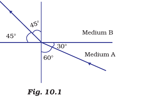
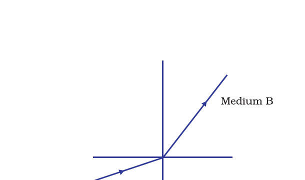
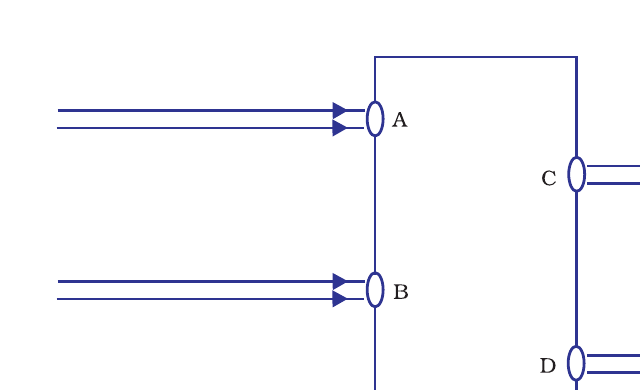
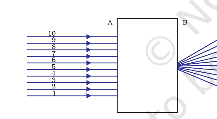
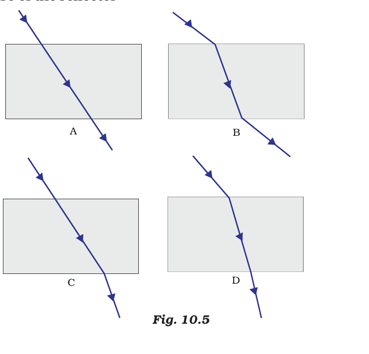
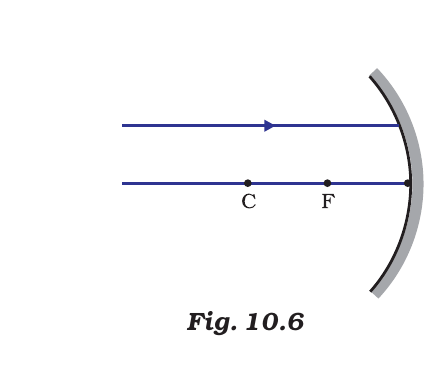
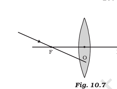


Comments