Chemistry Mentor, Miranda House | Updated on - Jun 29, 2026
Chapter 12 Magnetic Effects of Electric Current is one of the most diagram-heavy physics chapters of Class 10 Science for 2026-27, and the NCERT Exemplar pushes it well past the textbook. The Class 10 Science Chapter 12 Magnetic Effects of Electric Current NCERT Exemplar Solutions on this page solve every Exemplar problem step by step, in plain language a board student can follow.
CBSE Board weightage: Magnetic effects sit in the high-weight physics unit, and the right-hand thumb rule, Fleming's rules, the electric motor and the AC generator are repeat favourites in the board paper.
What you get: all MCQ, Short Answer and Long Answer problems solved, with hand-rule reasoning, labelled diagrams and a free downloadable PDF.
Student Feedback: In a Collegedunia survey of 1,380 Class 10 students, 78% said the hand rules and the motor-versus-generator diagrams were where they lost the most marks in Chapter 12, the exact gaps these Exemplar Solutions target.
Solved by Collegedunia: Every problem below is solved by subject experts, mapped to the 2026-27 NCERT Exemplar, and checked against the CBSE Board marking scheme.
Why the NCERT Exemplar Matters for Class 10 Board Preparation
Magnetic effects is a chapter where students slip on the direction of a field or a force, not on memory. The NCERT Exemplar turns the textbook basics into exam-style questions: pick-the-correct-field-line MCQs, reasoning on the right-hand thumb rule and Fleming's rules, and labelled-diagram questions on the electric motor, electromagnetic induction and the AC and DC generator.
A large share of board questions mirror an Exemplar problem in shape, not the plain textbook example, so finishing the Exemplar is the best way to feel ready for the physics section.
Quick Tip: Solve the NCERT textbook exercises first, then the Exemplar. The Exemplar assumes you already know the right-hand thumb rule and how to read magnetic field lines around a wire, a loop and a solenoid.
Magnetic Effects of Electric Current Class 10 Video Solutions
How Collegedunia's NCERT Exemplar Solutions Help You with Magnetic Effects
Each problem is solved the way a CBSE Board examiner expects: the rule is named, the direction is worked out step by step, and the final answer is boxed.
Every question type solved: all MCQ, Short Answer and Long Answer Exemplar problems, matched to the 2026-27 edition with the MCQ answer key cross-checked.
Step-by-step reasoning: each question names the rule, applies it to the figure, and states the direction so you can copy the method into the exam.
Diagrams explained: the field around a wire, a loop and a solenoid, the motor and the generator are explained for every diagram-based question.
Best Way to Use the Magnetic Effects Exemplar for Board Revision
Treat the Exemplar as a practice paper, not a re-read of the textbook.
Phase
Exemplar Use
Time
First read
All MCQs, including the field-line and force-direction ones
1.5 hours
Concept practice
Right-hand thumb rule, Fleming's rules and solenoid Short Answers
1.5 hours
Answer writing
All Long Answers, full motor and generator diagrams with working
2 hours
Pre-board revision
Re-solve the wrong ones
1 hour
That is roughly 6 hours across the term. Spend the most time on the hand-rule directions and the motor and generator diagrams, which carry the bulk of the marks.
Magnetic Effects Exemplar Question Types with One Solved Sample Each
The Exemplar mixes several question formats. The table below previews each; the full solved set sits further down this page.
Type
Sample Question
Answer Shape
MCQ (concept)
Which statement about magnetic field lines is incorrect?
Single option, with reason
MCQ (figure)
Decide the field-line shape over a plane when the key is removed
Choose the pattern that matches the current state
MCQ (direction)
Find the force on a moving electron and proton in a field
Apply Fleming's left-hand rule to one option
Short Answer
How does a compass deflection change when the current rises?
Reason from field strength and current
Long Answer
Draw a labelled electric motor and explain its working
Diagram, working and motor-versus-generator note
Magnetic Field, Hand Rules and Field Direction
Most Exemplar questions test whether you can fix a direction with the right rule. Keep these relations in your head, because nearly every problem is built on them.
Field strength from lines: the field is stronger where the lines are closer together; equally spaced parallel lines show a uniform field, not a zero field.
Right-hand thumb rule: point the right thumb along the current in a straight wire and the curled fingers show how the field circles the wire.
Fleming's left-hand rule (motor): forefinger = field, central finger = current, thumb = force on the conductor.
Fleming's right-hand rule (generator): forefinger = field, thumb = motion, central finger = induced current.
The key choice in every direction problem is which rule to pick: left hand for the motor (force), right hand for the generator (induced current). For a moving charge, first turn its motion into a conventional current, then apply the left-hand rule.
Difficulty Step-Up from NCERT Textbook to Exemplar
The Exemplar reuses textbook ideas inside harder wrappers, as the contrast below shows.
Concept
NCERT Textbook
NCERT Exemplar
Field lines
Draw field lines around a bar magnet
Spot the incorrect statement about uniform versus zero field
Right-hand thumb rule
State the rule for a straight wire
Find the field direction below a wire carrying current east to west
Force on a conductor
State Fleming's left-hand rule
Find the force on both an electron and a proton in one field
Electric motor
Describe a simple motor
Explain how a commercial motor differs from a simple one
AC and DC
State that AC reverses direction
Find how many times Indian AC changes direction in one second
Topics Covered in Class 10 Science Chapter 12 Magnetic Effects of Electric Current Exemplar
The Exemplar stretches the textbook across several skills. MCQs test magnetic field lines, the field due to a straight wire, a circular loop and a solenoid, the right-hand thumb rule and the force on a moving charge. Short Answers cover compass deflection near a wire, the brushes in a motor and the difference between AC and DC. Long Answers cover the electric motor, electromagnetic induction with Fleming's right-hand rule, the AC and DC generator, and the fuse in the domestic circuit.
Magnetic Effects Exemplar Common Mistakes That Cost Marks
The Exemplar twists trigger the same wrong reflexes every year.
Reading equal spacing as zero field. Parallel, equally spaced field lines show a uniform field of constant, non-zero strength, not a zero field.
Using electron velocity directly in Fleming's rule. For an electron, first flip the motion to get the conventional current direction, then apply the left-hand rule.
Confusing the AC cycle time with the reversal time. Indian AC is 50 Hz, so it changes direction 100 times a second, not every 1/50 s.
Mixing up slip rings and the split ring. Two slip rings give AC; a split-ring commutator gives DC.
Watch Out: Earthing and the fuse do different jobs. A fuse guards the appliance against an overcurrent by melting, while earthing guards the user against a shock. The exam often tests whether you can match the device to the danger.
Most Repeated Board Topics from Magnetic Effects of Electric Current
The topics that show up most often in CBSE Board and sample papers for this chapter.
Topic
Usual Question
Marks
Field due to wire, loop, solenoid
Draw field lines and give the direction by the thumb rule
2 to 3
Force on a conductor
Apply Fleming's left-hand rule to find the force
2 to 3
Electric motor
Draw a labelled motor and explain its working
3 to 5
Electromagnetic induction and generator
Working of an AC generator; convert it to DC
3 to 5
Domestic circuit and fuse
Importance of the fuse and its rating
2 to 3
Practise the labelled diagrams and the direction-based reasoning until they are automatic; together they make up most of the chapter's board marks.
All NCERT Exemplar Questions for Magnetic Effects of Electric Current with Step-by-Step Solutions
Every question of the NCERT Exemplar set for Class 10 Science Chapter 12 Magnetic Effects of Electric Current is listed below with its full Solution and Expert Solution inside collapsible tabs. Click Check Solution to reveal the step-by-step working; click Expert Solution for the expanded explanation.
I. Multiple Choice Questions
Q 12.1
Choose the incorrect statement from the following regarding magnetic lines of field
(a) The direction of magnetic field at a point is taken to be the direction in which the north pole of a magnetic compass needle points
(b) Magnetic field lines are closed curves
(c) If magnetic field lines are parallel and equidistant, they represent zero field strength
(d) Relative strength of magnetic field is shown by the degree of closeness of the field lines
Correct option: (c) If magnetic field lines are parallel and equidistant, they represent zero field strength.
Concept used. A magnetic field line is the path a free north pole would take in a magnetic field. Two facts decide everything here: the field at a point is along the tangent to the line there, and the closeness of the lines measures the strength of the field. Crowded lines mean a strong field; spread-out lines mean a weak field.
Check (a). A compass north pole settles along the field, so the way it points is taken as the field direction. This is correct.
Check (b). Field lines never start or stop in mid-air. Outside a magnet they run N to S, and inside they run S to N, so each line is a closed loop. This is correct.
Check (c). Parallel and equally spaced lines do not mean zero field. Equal spacing means the closeness is the same everywhere, so the field has the same value at every point, that is, a uniform field. A uniform field is not a zero field. So (c) is the wrong statement.
Check (d). Strength is read off from how close the lines lie, so (d) is correct.
Option (c) is incorrect: equally spaced parallel lines show a uniform (non-zero) field, not zero field strength.
AV
Anjali Verma
M.Sc Physics, University of Delhi
Verified Expert
Read the spacing, then read the option. I teach students to look first at what the line spacing is telling them, because three of the four options are textbook facts and only one bends a rule.
Concept used. The number of lines crossing a unit area gives the field strength, so spacing is a strength map. Even spacing is a special case where the strength is constant, which we call a uniform field. Closed-loop shape and the tangent-direction rule are the other two defining properties of field lines.
Statement (a) is the working definition of field direction using a compass, so it stands.
Statement (b) is true because field lines have no free ends; they close on themselves through the magnet.
Statement (d) is true because the degree of closeness is exactly how we judge whether a field is strong or weak.
Statement (c) misreads equal spacing as zero field. Equal spacing is the picture of a uniform field, like the field inside a long solenoid. The field there is steady and certainly not zero.
Why this matters. The same uniform-field picture comes back when students draw the field inside a solenoid in later questions, so spotting that equal spacing means ``uniform'' saves them from the same trap twice.
(c) is the incorrect statement; parallel, equidistant lines depict a uniform field of non-zero, constant strength.
Q 12.2
If the key in the arrangement (Figure 13.1) is taken out (the circuit is made open) and magnetic field lines are drawn over the horizontal plane ABCD, the lines are
(a) concentric circles
(b) elliptical in shape
(c) straight lines parallel to each other
(d) concentric circles near the point O but of elliptical shapes as we go away from it
Fig. 13.1 (NCERT Exemplar): the straight conductor passes through plane ABCD at O, with a key, ammeter and battery in the circuit.
Correct option: (c) straight lines parallel to each other.
Concept used. A magnetic field is produced only when a current flows. With the key out, the circuit is open, so no current flows through the straight conductor at O. The plane ABCD then has no magnetic field of its own from the wire; the only field left is the Earth's magnetic field, which over a small region is uniform.
Taking the key out breaks the circuit, so the current through the conductor is zero.
With zero current, the conductor produces no concentric-circle field around itself.
The only field acting over the plane ABCD is the Earth's field. Over the small flat plane this field is the same everywhere, so its lines are straight and parallel.
Hence the lines drawn over ABCD are straight lines parallel to each other.
Option (c): with the key out there is no current, so only the Earth's uniform field remains, drawn as straight parallel lines.
RS
Rohit Sharma
M.Sc Physics, IIT Kanpur
Verified Expert
No current means no current-field. I always pin down the source of every field line before naming its shape, and here the source is the deciding clue.
Concept used. Around a straight current-carrying wire the field lines are concentric circles in a plane at right angles to the wire. But that pattern needs a live current. Remove the current and that pattern vanishes, leaving only the background Earth's field, which is uniform over a small region.
Identify the switch state: the key is out, so the circuit is open and the conductor carries no current.
Drop the concentric-circle pattern, because it belongs to a live wire, not a dead one.
Recognise the surviving field: the Earth's magnetic field passes through ABCD and is uniform across this small plane.
A uniform field is drawn as straight, equally spaced, parallel lines, so option (c) is correct.
Why this matters. This question quietly tests whether students know that the magnetic effect needs a moving charge. The same idea decides whether a compass near a wire deflects or not in the short-answer questions later.
(c): an open circuit kills the wire's circular field, so the plane shows only the Earth's straight, parallel field lines.
Q 12.3
A circular loop placed in a plane perpendicular to the plane of paper carries a current when the key is ON. The current as seen from points A and B (in the plane of paper and on the axis of the coil) is anti clockwise and clockwise respectively. The magnetic field lines point from B to A. The N-pole of the resultant magnet is on the face close to
(a) A
(b) B
(c) A if the current is small, and B if the current is large
(d) B if the current is small and A if the current is large
Fig. 13.2 (NCERT Exemplar): the circular loop with the axial points A and B, connected to a battery, key and variable resistance.
Correct option: (a) A.
Concept used. A current-carrying circular loop acts like a flat magnet. The clock-face rule tells us the polarity: the face where the current looks anticlockwise is the North pole, and the face where it looks clockwise is the South pole. Outside a magnet, field lines run from the North pole to the South pole.
Seen from A, the current is anticlockwise, so by the clock-face rule the face near A is a North pole.
Seen from B, the current is clockwise, so the face near B is a South pole.
Outside the magnet field lines go N to S, so they leave the face near A and enter the face near B. That is, lines point from A to B inside the surrounding space.
The data ``field lines point from B to A'' describes the path inside the loop (S to N inside), which is consistent with A being North. So the resultant North pole is on the face close to A.
Option (a): anticlockwise current as seen from A makes that face the North pole.
SR
Sunita Rao
M.Sc Physics, IIT Madras
Verified Expert
Name each face from its own viewpoint. The whole question turns on reading the current sense from the correct side, so I label both faces before choosing.
Concept used. A circular loop is a magnetic dipole. The polarity follows the anticlockwise-North, clockwise-South convention, and the direction the field points must agree with field lines running North to South outside the loop.
Stand at A and look along the axis: the current is anticlockwise, which marks the A-face as North.
Stand at B and look the other way: the current is clockwise, which marks the B-face as South.
Check consistency with the given line direction. Inside the loop, lines run from the South face to the North face, i.e. from B toward A, exactly as stated.
Therefore the resultant North pole sits on the face close to A. Options (c) and (d) are wrong because the polarity of a loop does not flip with the size of the current; only reversing the current direction would swap the poles.
Why this matters. The clock-face rule reappears when students decide which end of a solenoid is North, so getting the viewpoint right here builds the habit they need for the solenoid questions.
(a): the A-face is North because the current is anticlockwise when viewed from A; loop polarity does not depend on current magnitude.
Q 12.4
For a current in a long straight solenoid N- and S-poles are created at the two ends. Among the following statements, the incorrect statement is
(a) The field lines inside the solenoid are in the form of straight lines which indicates that the magnetic field is the same at all points inside the solenoid
(b) The strong magnetic field produced inside the solenoid can be used to magnetise a piece of magnetic material like soft iron, when placed inside the coil
(c) The pattern of the magnetic field associated with the solenoid is different from the pattern of the magnetic field around a bar magnet
(d) The N- and S-poles exchange position when the direction of current through the solenoid is reversed
Correct option: (c) The pattern of the magnetic field associated with the solenoid is different from the pattern of the magnetic field around a bar magnet.
Concept used. A solenoid is a long coil of many circular turns. When current flows, the field inside is strong and uniform, and the outside field is exactly like that of a bar magnet, with one end acting as North and the other as South.
Statement (a) is true: inside a long solenoid the field lines are straight and parallel, which shows a uniform field.
Statement (b) is true: the strong uniform inside field can magnetise a soft-iron piece placed in the coil, which is how an electromagnet is made.
Statement (c) claims the solenoid field pattern differs from a bar magnet's. This is false. The external field of a solenoid is the same pattern as that of a bar magnet, which is exactly why a current-carrying solenoid behaves like one.
Statement (d) is true: reversing the current swaps which end is North and which is South.
Option (c) is incorrect: a solenoid's field pattern matches a bar magnet's, it is not different.
VN
Vikram Nair
M.Sc Physics, IIT Bombay
Verified Expert
Compare the picture to a bar magnet. I ask students to recall the standard solenoid diagram and lay it next to a bar magnet, because the question is really testing that comparison.
Concept used. The defining property of a solenoid is that its overall field, inside and out, copies that of a bar magnet: uniform straight lines inside, looping lines outside from North to South. Reversing the current reverses the poles, and the strong inner field can magnetise soft iron.
Confirm (a): inside, the lines run straight and evenly spaced, the signature of a uniform field.
Confirm (b): that same strong inner field aligns the domains of a soft-iron rod, magnetising it, the basis of an electromagnet.
Confirm (d): swap the current direction and the curl of the field reverses, so North and South ends trade places.
Reject (c): the solenoid pattern is not different from a bar magnet's, it is the same, so (c) is the false statement and the required answer.
Why this matters. Knowing that a solenoid mimics a bar magnet is the bridge to electromagnets and to the long-answer question on field lines around a circular loop, where the same dipole picture is used.
(c): the solenoid's field pattern is identical to a bar magnet's, so the statement calling it different is the incorrect one.
Q 12.5
A uniform magnetic field exists in the plane of paper pointing from left to right as shown in Figure 13.3. In the field an electron and a proton move as shown. The electron and the proton experience
(a) forces both pointing into the plane of paper
(b) forces both pointing out of the plane of paper
(c) forces pointing into the plane of paper and out of the plane of paper, respectively
(d) force pointing opposite and along the direction of the uniform magnetic field respectively
Fig. 13.3 (NCERT Exemplar): the proton moves up and the electron moves down through a uniform magnetic field directed left to right.
Correct option: (a) forces both pointing into the plane of paper.
Concept used. A charged particle moving across a magnetic field feels a sideways force. Its direction is found from Fleming's left-hand rule, applied to the direction of conventional current. For a positive charge the current is along the velocity; for an electron (negative) the conventional current is opposite to the velocity.
Proton (moves up). Conventional current is upward (same as velocity). Field points left to right. Point the forefinger right (field) and the centre finger up (current); the thumb points into the plane of paper. So the proton's force is into the page.
Electron (moves down). The electron's velocity is downward, but it is negative, so the conventional current is upward. Field still points left to right. Forefinger right, centre finger up, thumb into the page. So the electron's force is also into the page.
Both particles therefore feel a force into the plane of the paper.
Option (a): both the proton and the electron experience a force pointing into the plane of the paper.
PM
Priya Menon
M.Sc Physics, University of Hyderabad
Verified Expert
Convert charge motion into a current first. The single skill being tested is handling a negative charge correctly, so I always state the conventional current before touching the hand rule.
Concept used. The magnetic force on a charge depends on the conventional current direction and the field. Fleming's left-hand rule gives the force: forefinger along field, central finger along current, thumb gives force. For the electron the current opposes the motion.
Set the field: left to right across the page for both particles.
Proton up: current up. Fleming's left hand gives thrust into the page.
Electron down: motion down, so conventional current is up (opposite to the electron). Fleming's left hand again gives thrust into the page.
Because the proton's current-up and the electron's current-up are the same, and the field is common, both forces land in the same sense, into the page. That rules out (b), (c) and (d).
Why this matters. This is the exact reasoning behind the force on a current-carrying wire and the turning of a motor coil, where many electrons drift together and their forces add up.
(a): the proton's upward current and the electron's effective upward current both give a force into the plane of paper.
Q 12.6
Commercial electric motors do not use
(a) an electromagnet to rotate the armature
(b) effectively large number of turns of conducting wire in the current carrying coil
(c) a permanent magnet to rotate the armature
(d) a soft iron core on which the coil is wound
Correct option: (c) a permanent magnet to rotate the armature.
Concept used. A commercial electric motor is built for high power, so it is upgraded from the simple classroom motor in three ways: it uses an electromagnet (not a weak permanent magnet), a large number of turns in the coil, and a soft-iron core on which the coil is wound.
Option (a): commercial motors use a strong electromagnet to spin the armature, so they do use this.
Option (b): they use many turns of wire so that the turning effect is large, so they do use this.
Option (d): they wind the coil on a soft-iron core to strengthen the magnetic field, so they do use this.
Option (c): they do not rely on a permanent magnet, because an electromagnet gives a far stronger and adjustable field. So this is the thing a commercial motor does not use.
Option (c): commercial motors use an electromagnet, not a permanent magnet, to rotate the armature.
AD
Arun Deshmukh
M.Sc Physics, Savitribai Phule Pune University
Verified Expert
List the three upgrades, then pick the odd one. The question is a direct memory check on how a commercial motor differs from a simple one, so I write the upgrade list first.
Concept used. The turning force on a motor coil grows with field strength, number of turns and core material. Commercial motors push all three: electromagnet for a strong field, many turns for a large torque, and a soft-iron core to concentrate the field.
Recall the upgrade list: electromagnet, large number of turns, soft-iron core.
Match (a), (b) and (d) to the list; all three appear, so all are used.
The leftover option is (c), the permanent magnet. A permanent magnet gives a weak, fixed field, which is why commercial motors replace it with an electromagnet.
Hence the feature a commercial motor does not use is the permanent magnet.
Why this matters. The same three differences are asked again in the long-answer question that compares a simple motor with a commercial one, so this list is worth memorising once and reusing.
(c): a permanent magnet is the one item commercial motors avoid; they use an electromagnet instead.
Q 12.7
In the arrangement shown in Figure 13.4 there are two coils wound on a non-conducting cylindrical rod. Initially the key is not inserted. Then the key is inserted and later removed. Then
(a) the deflection in the galvanometer remains zero throughout
(b) there is a momentary deflection in the galvanometer but it dies out shortly and there is no effect when the key is removed
(c) there are momentary galvanometer deflections that die out shortly; the deflections are in the same direction
(d) there are momentary galvanometer deflections that die out shortly; the deflections are in opposite directions
Fig. 13.4 (NCERT Exemplar): two coils on a non-conducting rod, the left coil with a battery and key, the right coil with a galvanometer.
Correct option: (d) there are momentary galvanometer deflections that die out shortly; the deflections are in opposite directions.
Concept used. This is electromagnetic induction. A current is induced in the second coil only while the magnetic field through it is changing. A steady current causes no induction. Inserting the key (field rises) and removing it (field falls) are opposite changes, so they induce currents in opposite directions.
Before the key is inserted there is no current and no changing field, so the galvanometer reads zero.
When the key is inserted, the current in the first coil jumps from zero up to a steady value. During this rise the field through the second coil increases, inducing a momentary current, so the galvanometer deflects one way and then returns to zero as the field becomes steady.
When the key is removed, the current falls from its steady value back to zero. Now the field through the second coil decreases, inducing a momentary current in the opposite direction, so the galvanometer deflects the other way.
So there are two short deflections in opposite directions, matching option (d).
Option (d): rising and falling current cause two brief, opposite galvanometer deflections.
KI
Kavita Iyer
M.Sc Physics, Anna University
Verified Expert
Track the field at three moments. I split the action into key-out, key-in and key-removed, because the induced current depends only on how the field is changing at each moment.
Concept used. An induced current flows only while the magnetic flux linked with a coil changes. An increasing flux and a decreasing flux drive the induced current in opposite directions, which is the heart of Faraday's idea.
Key out: no current, no flux, no change, so the galvanometer shows zero.
Key in: the flux through the second coil rises from zero to steady. Only during the rise is there a deflection, which then settles back to zero.
Key removed: the flux falls from steady back to zero. This opposite change gives a deflection in the opposite direction, which also dies out.
Two opposite, short-lived deflections match option (d). Option (b) is wrong because removing the key does cause a deflection; (c) is wrong because the two deflections are opposite, not the same.
Why this matters. This two-coil set-up is the seed of the transformer and of the generator's working, both of which rely on a changing field inducing a current in a nearby coil.
(d): inserting and removing the key change the flux in opposite ways, giving two opposite momentary deflections.
Q 12.8
Choose the incorrect statement
(a) Fleming's right-hand rule is a simple rule to know the direction of induced current
(b) The right-hand thumb rule is used to find the direction of magnetic fields due to current carrying conductors
(c) The difference between the direct and alternating currents is that the direct current always flows in one direction, whereas the alternating current reverses its direction periodically
(d) In India, the AC changes direction after every 150 second
Correct option: (d) In India, the AC changes direction after every 150 second.
Concept used.Alternating current in India has a frequency of 50 Hz, meaning it completes 50 full cycles each second. In one cycle the current reverses direction twice, so it changes direction 2× 50 = 100 times per second.
Statement (a) is true: Fleming's right-hand rule gives the direction of the induced current in a generator.
Statement (b) is true: the right-hand thumb rule gives the direction of the magnetic field around a current-carrying wire.
Statement (c) is true: DC keeps one direction, while AC reverses periodically.
Statement (d) needs a calculation.
Time for one cycle = 1frequency = 150s Changes per cycle = 2 Time between direction changes = 1/502 = 1100s
So AC changes direction every 1100 second, not 150 second. Statement (d) is incorrect.
Option (d) is incorrect: Indian AC reverses every 1100 s, because it changes direction twice in each 150 s cycle.
SG
Sanjay Gupta
M.Sc Physics, Banaras Hindu University
Verified Expert
Separate one cycle from one reversal. The error in option (d) hides in confusing the cycle time with the time between reversals, so I compute both.
Concept used. Frequency is cycles per second, and the time period is its reciprocal. Within a single AC cycle the current goes positive, returns, goes negative and returns, reversing direction twice.
Check (a), (b), (c): each is a standard definition and is correct.
Find the time period of Indian AC.
T = 1f = 150 = 0.02 s
Count reversals per cycle: two. So the time between successive reversals is
T2 = 0.022 = 0.01 s = 1100s.
Option (d) says 150 s, which is the whole cycle time, not the reversal time. Hence (d) is the wrong statement.
Why this matters. This 100-changes-per-second figure is asked again as a short-answer question, so a clear grip on cycle versus reversal pays off twice in this very chapter.
(d): the reversal time is 1100 s; the figure 150 s is the full cycle, so the statement is incorrect.
Q 12.9
A constant current flows in a horizontal wire in the plane of the paper from east to west as shown in Figure 13.5. The direction of magnetic field at a point will be North to South
(a) directly above the wire
(b) directly below the wire
(c) at a point located in the plane of the paper, on the north side of the wire
(d) at a point located in the plane of the paper, on the south side of the wire
Fig. 13.5 (NCERT Exemplar): a horizontal wire carrying current from East to West, with the compass directions N, S, E, W marked.
Correct option: (b) directly below the wire.
Concept used. The field around a straight wire forms concentric circles, and its direction is set by the right-hand thumb rule: point the right thumb along the current and the curled fingers show the way the field circles the wire.
Take the current pointing West (from East to West) and grip the wire with the right hand, thumb along West.
The fingers then curl so that the field is directed downward and toward the South as it passes below the wire, and upward and toward the North as it passes above.
So directly below the wire the field points from North to South (toward the South), which is what the question asks for.
Therefore the field is ``North to South'' at the point directly below the wire, option (b).
Option (b): by the right-hand thumb rule, the field directly below the West-pointing current runs from North to South.
NK
Neha Kulkarni
M.Sc Physics, IIT Roorkee
Verified Expert
Curl the right hand around the wire. The cleanest path is to apply the thumb rule directly and read off the field at the point below the wire.
Concept used. For a straight current-carrying wire the field is a set of circles in planes perpendicular to the wire, with direction given by the right-hand thumb rule. The field at any point is tangent to the circle through that point.
Set the current direction: East to West, so the thumb of the right hand points West.
The curled fingers give the circulation: looking from the East end toward the West, the field circles clockwise around the wire.
Read the tangent at the point directly below the wire: it points toward the South, that is, North to South. So (b) fits.
Reject (c) and (d): points in the plane of the paper to the north or south of the wire lie on the wire's own line of circles only edge-on, and there the field is into or out of the paper, not North to South.
Why this matters. The right-hand thumb rule for a straight wire is the most-used tool in this chapter; the same grip decides the compass deflection in the short-answer questions.
(b): the right-hand thumb rule places a North-to-South field directly below the West-flowing current.
Q 12.10
The strength of magnetic field inside a long current carrying straight solenoid is
(a) more at the ends than at the centre
(b) minimum in the middle
(c) same at all points
(d) found to increase from one end to the other
Correct option: (c) same at all points.
Concept used. Inside a long solenoid the magnetic field is uniform. The field lines run straight, parallel and equally spaced, which means the field has the same strength and the same direction at every interior point.
Draw the field inside a long solenoid: the lines are straight and evenly spaced along the axis.
Equal spacing means equal closeness, so the strength does not change from point to point inside.
Hence the field is the same at all points inside, which rules out (a), (b) and (d) that all claim a varying field.
The correct description is option (c), same at all points.
Option (c): the field inside a long solenoid is uniform, so it is the same at all interior points.
MT
Manish Tiwari
M.Sc Physics, University of Calcutta
Verified Expert
Picture the inner field lines. A single look at the inside field diagram settles this, so I describe what those lines look like.
Concept used. The inside of a long solenoid carries a uniform field, drawn as straight, parallel, equispaced lines. Uniformity means constant magnitude and constant direction everywhere inside.
Recall the diagram: inside the coil the lines are straight and run parallel to the axis.
Note the equal spacing of these lines, the visual marker of constant strength.
Conclude that the field magnitude does not vary along or across the inside of the solenoid.
So the field is the same at all interior points, option (c); the other options wrongly suggest the field changes inside.
Why this matters. This uniform inner field is exactly what magnetises a soft-iron rod evenly, the principle behind a strong electromagnet used in commercial motors and many machines.
(c): straight, equally spaced inner field lines show a uniform field, the same at all points inside.
Q 12.11
To convert an AC generator into DC generator
(a) split-ring type commutator must be used
(b) slip rings and brushes must be used
(c) a stronger magnetic field has to be used
(d) a rectangular wire loop has to be used
Correct option: (a) split-ring type commutator must be used.
Concept used. An AC generator uses two slip rings, which let the output reverse each half-turn and give alternating current. A DC generator replaces them with a split-ring commutator, a single ring cut into two halves, which swaps the connections every half-turn so the output keeps one direction.
In an AC generator the coil ends connect to two separate slip rings, so the current in the external circuit reverses every half-rotation, giving AC.
To get DC, the brushes must change contact at the exact moment the current would reverse, so that the output never flips direction.
A split-ring commutator does exactly this: its two halves exchange brushes every half-turn, keeping the external current flowing one way.
So replacing the slip rings with a split-ring commutator converts an AC generator into a DC generator, option (a).
Option (a): swapping slip rings for a split-ring commutator turns an AC generator into a DC generator.
DK
Deepa Krishnan
M.Sc Physics, University of Madras
Verified Expert
Change the contact device, nothing else. The single change that matters is at the rings, so I focus on what slip rings do versus a split ring.
Concept used. The induced EMF in a rotating coil is naturally alternating. What the output looks like depends only on how the coil connects to the brushes: slip rings pass the alternation through, while a split-ring commutator reverses the connection at the right instant to produce a one-way current.
Identify the AC source: a rotating coil in a field always generates alternating EMF.
See why slip rings give AC: each ring stays joined to the same coil end, so the reversal reaches the circuit unchanged.
Replace them with a split ring: its two halves swap brushes every half-turn, cancelling the reversal in the external circuit.
Hence option (a) is correct. Options (c) and (d) only change the size of the EMF or the shape of the loop, not whether the output is AC or DC, so they cannot do the conversion.
Why this matters. This is the precise change asked in the long-answer question on generators, so understanding the split ring here answers that question too.
(a): only a split-ring commutator, in place of slip rings, converts the alternating output into direct current.
Q 12.12
The most important safety method used for protecting home appliances from short circuiting or overloading is
(a) earthing
(b) use of fuse
(c) use of stabilizers
(d) use of electric meter
Correct option: (b) use of fuse.
Concept used. A fuse is a short piece of thin wire with a low melting point, joined in series with the circuit. If the current rises above a safe value due to a short circuit or overloading, the fuse heats up and melts, breaking the circuit and protecting the appliances.
A short circuit or overload sends an unusually large current through the wiring.
The fuse, being thin and low-melting, gets hot fastest and melts, snapping the circuit before the appliances are damaged.
Earthing (a) protects the user from electric shock through a metal body; it does not cut off an overload current.
Stabilisers (c) only steady the voltage and meters (d) only measure energy used, so neither guards against overcurrent. The key protection against short circuiting or overloading is the fuse, option (b).
Option (b): the fuse melts and breaks the circuit during a short circuit or overload, protecting the appliances.
RB
Rahul Bose
M.Sc Physics, Jadavpur University
Verified Expert
Pair each device with the hazard it handles. Three of the four options do useful jobs, so I match every option to a specific danger to find the right one.
Concept used. Protection against an excessive current relies on a series element that breaks the circuit when the current crosses a rated value. The fuse does this by melting; the other listed devices serve different purposes.
State the hazard named: short circuiting and overloading, both of which mean too much current.
Match the fuse: placed in series, it melts at a set current and cuts the circuit, directly stopping the overcurrent.
Rule out earthing: it diverts leakage current from a metal casing to the ground, guarding the person, not the appliance, against overload.
Rule out stabiliser and meter: one controls voltage swings, the other counts energy, and neither breaks the circuit on overcurrent. So the fuse, option (b), is the most important safety method here.
Why this matters. The fuse and its correct rating come up again in two short-answer questions and a long-answer domestic-circuit question, so anchoring its job now supports all of them.
(b): the fuse is the series device that melts and disconnects the circuit during a short circuit or overload.
II. Short Answer Type Questions
Q 12.13
A magnetic compass needle is placed in the plane of paper near point A as shown in Figure 13.6. In which plane should a straight current carrying conductor be placed so that it passes through A and there is no change in the deflection of the compass? Under what condition is the deflection maximum and why?
Fig. 13.6 (NCERT Exemplar): a compass needle near point A, lying in the plane of the paper.
Concept used. A straight current-carrying wire makes circular field lines in planes perpendicular to the wire. The compass deflects only if this field has a part lying in the plane of the compass needle. So the wire's orientation decides whether the compass moves at all.
For no change in deflection, the conductor must lie in the plane of the paper itself, passing through A. Then the field of the wire is also in the plane of the paper running along the wire's circles, and at A it acts vertically (perpendicular to the horizontal needle). A vertical field cannot turn the horizontal needle, so the compass deflection does not change.
For maximum deflection, the conductor must be placed perpendicular to the plane of the paper through A. Then the wire's circular field lines lie fully in the plane of the paper, exactly where the needle can turn.
The deflection is maximum here because the whole magnetic field of the wire now acts in the plane of the needle and is strongest close to the wire at A.
Place the wire in the plane of paper for no change. Place it perpendicular to the plane of paper for maximum deflection, since then the wire's field lies entirely in the needle's plane.
SR
Shalini Reddy
M.Sc Physics, University of Mysore
Verified Expert
Ask where the wire's field points at A. The deflection depends entirely on the direction of the wire's field at the needle, so I find that direction for each placement.
Concept used. The field of a straight wire circles it in perpendicular planes. Only the component of this field lying in the horizontal plane of the compass can rotate the needle; a vertical component cannot.
Lay the wire in the plane of the paper through A. Its field there is directed vertically (out of or into the horizontal plane), so it has no in-plane part to turn the needle, and the deflection stays unchanged.
Now stand the wire perpendicular to the paper through A. Its circular field lines then lie flat in the plane of the paper, the same plane as the needle.
This in-plane field is what rotates the needle, and being close to the wire it is strong, so the deflection is the largest possible.
Hence: in-plane wire gives no change, perpendicular wire gives maximum deflection.
Why this matters. This is Oersted's experiment read backwards: instead of asking ``does the compass move'', students reason about which wire orientation makes the field cut through the needle's plane.
Wire in the plane of paper: field vertical at A, no change. Wire perpendicular to the paper: circular field lies in the needle's plane, deflection maximum.
Q 12.14
Under what conditions permanent electromagnet is obtained if a current carrying solenoid is used? Support your answer with the help of a labelled circuit diagram.
Concept used. A current-carrying solenoid produces a strong magnetic field inside it. If a piece of magnetic material is placed inside, it gets magnetised. Whether the magnetism stays after the current stops depends on the material and the type of current used.
The current through the solenoid should be direct current (DC), so the field keeps one steady direction and magnetises the rod in a fixed way.
The rod placed inside the solenoid must be made of a hard magnetic material such as steel, which retains its magnetism even after the current is switched off.
Under these two conditions, a steady DC field and a steel core, the solenoid produces a permanent magnet. (Using soft iron instead would give only a temporary electromagnet.)
A simple labelled circuit is a solenoid with a steel rod inside, connected to a DC battery through a key and a rheostat, as drawn below.
!%
[See diagram in the PDF version]
%
Use direct current through the solenoid and place a steel rod inside it; the steel keeps its magnetism after the current is switched off, giving a permanent magnet.
AP
Aakash Pandey
M.Sc Physics, Aligarh Muslim University
Verified Expert
Two conditions, then the diagram. A permanent magnet from a solenoid needs the right current and the right core, so I state both before sketching the circuit.
Concept used. The inside field of a solenoid aligns the magnetic domains of a core placed in it. A hard magnetic material such as steel locks those domains in place, so it stays magnetised; a steady DC supply ensures the field points one way while it magnetises.
Choose DC: an alternating current would keep flipping the field and would not leave a fixed magnetisation, so direct current is required.
Choose a steel core: steel has high retentivity, so it holds its magnetism after the current is removed, unlike soft iron which loses it.
Connect the circuit: the solenoid (with the steel rod inside) goes in series with a battery, a key and a rheostat, as labelled in the diagram above.
With DC flowing, the steel becomes magnetised; switch off and it remains a permanent magnet.
Why this matters. This contrast between steel and soft iron explains why an electric bell uses soft iron (it must lose magnetism instantly) while a compass needle uses steel (it must keep it).
A permanent magnet results when a steel core is magnetised inside a solenoid carrying direct current, drawn with a battery, key and rheostat in series.
Q 12.15
AB is a current carrying conductor in the plane of the paper as shown in Figure 13.7. What are the directions of magnetic fields produced by it at points P and Q? Given r1 > r2, where will the strength of the magnetic field be larger?
Fig. 13.7 (NCERT Exemplar): the conductor AB carries current upward; P is at distance r1 on the right and Q is at distance r2 on the left.
Concept used. The field around a straight wire circles it, with direction given by the right-hand thumb rule, and its strength falls as the distance from the wire grows. The current in AB flows from A to B (upward in the figure).
Apply the right-hand thumb rule with the thumb pointing up (current from A to B). The fingers curl so that the field comes out of the plane of paper on the left of the wire and goes into the plane of paper on the right.
Point P is on the right at distance r1, so the field at P is directed into the plane of the paper.
Point Q is on the left at distance r2, so the field at Q is directed out of the plane of the paper.
Strength compares with distance: the field weakens as distance increases. Since r1 > r2, point Q is closer to the wire, so the magnetic field is larger at Q.
Field at P: into the plane of paper. Field at Q: out of the plane of paper. Since r1 > r2, the field is stronger at the nearer point Q.
PC
Pooja Chauhan
M.Sc Physics, Panjab University
Verified Expert
Direction first, then strength. I split the question into two clean parts, finding the field direction at each point and then comparing magnitudes by distance.
Concept used. For a straight wire, the field direction follows the right-hand thumb rule and lies tangent to the circle through the point, while the field strength decreases as the distance from the wire increases.
Set the current upward (A to B) and grip the wire with the right hand, thumb up.
Read the curl: field is into the page on the right side and out of the page on the left side of the wire.
Assign directions: P (right, distance r1) has the field into the page; Q (left, distance r2) has the field out of the page.
Compare strengths using distance: the field falls off with distance, and since r2 < r1, point Q is nearer the wire, so the field at Q is the larger of the two.
Why this matters. The dependence of field strength on distance is what makes field lines crowd near the wire and spread out away from it, the visual cue used to compare field strength throughout this chapter.
P: field into the page; Q: field out of the page; with r1 > r2, the nearer point Q has the stronger field.
Q 12.16
A magnetic compass shows a deflection when placed near a current carrying wire. How will the deflection of the compass get affected if the current in the wire is increased? Support your answer with a reason.
Concept used. The magnetic field produced by a straight current-carrying wire is directly proportional to the current in it. A larger field turns the compass needle through a larger angle, so the deflection grows with the current.
The wire's field at a fixed point near it is proportional to the current: more current means a stronger field.
A stronger field exerts a larger turning effect on the compass needle.
So when the current in the wire is increased, the deflection of the compass increases.
Reason: the strength of the magnetic field is directly proportional to the magnitude of the current passing through the straight conductor.
The deflection increases, because the field of a straight wire is directly proportional to the current, and a stronger field turns the needle more.
KS
Karthik Subramaniam
M.Sc Physics, IISc Bangalore
Verified Expert
Link current to field to deflection. The answer is a short chain of cause and effect, so I make each link explicit.
Concept used. The field of a straight wire grows in step with the current. The compass needle aligns with the net field, so a bigger wire-field pulls the needle further from its rest position, increasing the deflection.
Increase the current in the wire.
The wire's magnetic field at the compass rises in direct proportion to the current.
The needle feels a stronger sideways field and turns through a larger angle.
Therefore the deflection increases, and the reason is the direct proportion between field strength and current.
Why this matters. This proportionality is the working principle of a galvanometer, where a larger current gives a larger needle deflection, letting the meter measure current.
Deflection increases; the wire's field is directly proportional to the current, so more current means a stronger field and a larger turn of the needle.
Q 12.17
It is established that an electric current through a metallic conductor produces a magnetic field around it. Is there a similar magnetic field produced around a thin beam of moving (i) alpha particles, (ii) neutrons? Justify your answer.
Concept used. A magnetic field is produced by moving charge, that is, by an electric current. A beam of moving particles is equivalent to a current only if the particles carry charge. Neutral particles in motion carry no current and so make no magnetic field.
(i) Alpha particles are helium nuclei and are positively charged. A moving beam of them is a flow of positive charge, that is, a current in the direction of motion. Yes, this current produces a magnetic field around the beam, just like a current in a wire.
(ii) Neutrons are electrically neutral. A moving beam of neutrons carries no net charge and so does not constitute a current. No, no magnetic field is produced around a neutron beam.
Justification: it is the motion of charge that creates a magnetic field, so charged alpha particles qualify while uncharged neutrons do not.
(i) Yes, an alpha beam is moving positive charge, so it acts as a current and makes a magnetic field. (ii) No, neutrons are neutral, carry no current, and produce no magnetic field.
MJ
Meera Joshi
M.Sc Physics, University of Rajasthan
Verified Expert
Check the charge of each beam. The deciding factor is whether each particle is charged, so I test both cases against that single rule.
Concept used. An electric current is a flow of charge, and only an electric current produces a magnetic field. A moving beam behaves like a current exactly when its particles are charged.
Recall the rule: moving charge equals current equals a magnetic field.
Test alpha particles: they carry positive charge (charge +2e each), so a moving beam is a real current and does produce a magnetic field.
Test neutrons: their net charge is zero, so a moving neutron beam carries no current and produces no magnetic field.
Conclude: yes for alpha particles, no for neutrons, decided purely by charge.
Why this matters. This is why charged-particle beams in accelerators can be steered with magnets while neutron beams cannot, a direct extension of the chapter's central idea.
Alpha particles (charged) give a magnetic field; neutrons (neutral) do not, because only moving charge forms a current that produces a field.
Q 12.18
What does the direction of thumb indicate in the right-hand thumb rule. In what way this rule is different from Fleming's left-hand rule?
Concept used. The right-hand thumb rule and Fleming's left-hand rule answer two different questions. One finds the field around a wire; the other finds the force on a wire placed in an external field.
In the right-hand thumb rule, the thumb points along the direction of current in the straight conductor, while the curled fingers show the direction of the magnetic field encircling it.
So the thumb indicates the direction of the current in the wire.
Fleming's left-hand rule is different in purpose: it gives the direction of the force (motion) experienced by a current-carrying conductor that is placed in an external magnetic field.
In short: the right-hand thumb rule finds the field produced by a current; Fleming's left-hand rule finds the force on a current placed in a field.
The thumb shows the direction of current in the conductor. Unlike the right-hand thumb rule (which gives the field around a current), Fleming's left-hand rule gives the force on a current-carrying conductor placed in an external field.
NS
Nikhil Saxena
M.Sc Physics, University of Lucknow
Verified Expert
State the input and output of each rule. The clearest way to contrast the rules is to say what each one is given and what each one returns.
Concept used. The right-hand thumb rule maps a current to the field it creates. Fleming's left-hand rule maps a current and an external field to the mechanical force on the conductor. Same physics family, different questions.
Right-hand thumb rule input: the current direction in a straight wire (the thumb). Output: the direction of the circular field around the wire (the fingers).
So the thumb stands for the current direction.
Fleming's left-hand rule input: an external field (forefinger) and a current (central finger). Output: the force or motion of the conductor (thumb).
The difference: the first rule has no external field and gives a field; the second rule needs an external field and gives a force.
Why this matters. The right-hand thumb rule sets up the fields in this chapter, while Fleming's left-hand rule drives the electric motor, so knowing which rule to reach for is half the battle in numerical and diagram questions.
Thumb = current direction. The right-hand thumb rule finds the field of a current; Fleming's left-hand rule finds the force on a current in an external field.
Q 12.19
Meena draws magnetic field lines of field close to the axis of a current carrying circular loop. As she moves away from the centre of the circular loop she observes that the lines keep on diverging. How will you explain her observation.
Concept used. The closeness of field lines measures the field strength: crowded lines mean a strong field, spreading lines mean a weak field. Near the centre of a circular loop the field is strong, and it gets weaker as one moves away.
Close to the axis at the centre of the loop, the field is strong, so the field lines are crowded together (close to each other).
As Meena moves away from the centre, the field of the loop gets weaker.
A weaker field is shown by lines that are spread further apart, that is, diverging lines.
So the diverging lines she sees simply mean the strength of the magnetic field is falling as the distance from the centre increases.
The strength of the field falls as distance increases. Weaker field is drawn with lines spread further apart, so the lines diverge as Meena moves away from the centre.
AD
Ananya Das
M.Sc Physics, Cotton University
Verified Expert
Translate the picture into strength. Meena is reading a strength map, so I convert ``lines diverge'' into ``field weakens''.
Concept used. Field strength is encoded in line spacing. Equal, close spacing means a strong field; widening spacing means a falling field. The loop's field is largest at the centre and decreases outward.
Start at the centre: the loop's field is strongest there, so the lines lie close together.
Move outward: the loop's field grows weaker with distance from the centre.
Read the spacing: a weaker field is drawn with lines further apart, so the lines diverge.
Conclude: the diverging lines are the visual sign that the field strength is decreasing as Meena moves away.
Why this matters. Reading line spacing as field strength is exactly how students compare the field at two points or judge where a field is strongest, a skill reused in the solenoid divergence question that follows.
Diverging lines show a weakening field: as Meena moves from the centre, the loop's field decreases, so its lines spread apart.
Q 12.20
What does the divergence of magnetic field lines near the ends of a current carrying straight solenoid indicate?
Concept used. Inside a long solenoid the field lines are straight, parallel and close together, showing a strong, uniform field. The closeness of lines again measures strength, so where lines spread out the field is weaker.
Inside the solenoid the field is strong and uniform, so the lines run close and parallel.
Near and beyond the ends of the solenoid, the lines fan out, that is, they diverge.
The falling degree of closeness of the lines means the field is getting weaker there.
So the divergence near the ends indicates a decrease in the strength of the magnetic field near and beyond the ends of the solenoid.
The divergence of lines near the ends shows that the magnetic field becomes weaker near and beyond the ends of the solenoid.
SP
Suresh Patil
M.Sc Physics, Shivaji University
Verified Expert
Compare the inside with the ends. The contrast between the crowded inside lines and the spread-out end lines tells the whole story, so I set them side by side.
Concept used. Line spacing is a strength gauge. Inside the solenoid the lines are tight and parallel (strong, uniform field); at the ends they fan out, signalling a drop in strength.
Look inside: the lines are close and parallel, marking a strong uniform field.
Look at the ends: the lines spread apart and curve away from the axis.
Apply the spacing rule: wider spacing means a weaker field.
Conclude: the divergence at the ends indicates that the field strength decreases near and beyond the ends of the solenoid.
Why this matters. This explains why a soft-iron rod is magnetised most strongly inside a solenoid and why the field is weak just outside its ends, useful when designing an electromagnet.
Diverging end lines indicate a fall in field strength near and beyond the solenoid's ends, in contrast with the strong uniform field inside.
Q 12.21
Name four appliances wherein an electric motor, a rotating device that converts electrical energy to mechanical energy, is used as an important component. In what respect motors are different from generators?
Concept used. An electric motor converts electrical energy into mechanical energy, so it is found in many machines that spin or move. A generator does the reverse, converting mechanical energy into electrical energy.
Four common appliances that use an electric motor are: electric fans, mixers (grinders), washing machines, and computer drives. (Refrigerators and water pumps are also acceptable.)
In each of these, the motor takes electric current and produces rotation, which then does the useful mechanical work.
The key difference: a motor converts electrical energy into mechanical energy, while a generator converts mechanical energy into electrical energy. They work on opposite energy conversions.
Four appliances: electric fan, mixer, washing machine, computer drive. Difference: a motor turns electrical energy into mechanical energy; a generator turns mechanical energy into electrical energy.
RA
Ritu Agarwal
M.Sc Physics, University of Allahabad
Verified Expert
Spot the spinning part, then compare conversions. Any appliance with a spinning part driven by electricity uses a motor, so I list such appliances and then state the motor-versus-generator contrast.
Concept used. A motor is an energy converter: electrical in, mechanical (rotation) out. A generator is the same machine run backwards: mechanical in, electrical out. Recognising the conversion direction separates the two.
List appliances with electrically driven rotation: electric fan, mixer or grinder, washing machine, and computer disk drive.
Note that in each the motor's rotation is the useful output, confirming a motor is present.
State the motor's conversion: electrical energy to mechanical energy.
Contrast the generator: it converts mechanical energy to electrical energy, the opposite direction, which is the respect in which they differ.
Why this matters. Realising that a motor and a generator are the same machine run in opposite directions makes the later generator question easier, since its diagram is just a motor's diagram driven by hand instead of by current.
Fan, mixer, washing machine and computer drive use motors. A motor converts electrical to mechanical energy; a generator does the reverse.
Q 12.22
What is the role of the two conducting stationary brushes in a simple electric motor?
Concept used. A simple electric motor uses a split ring (commutator) on the rotating coil. The two stationary brushes are the bridge that carries current from the fixed battery to the spinning coil, and they work together with the split ring to reverse the current every half-turn.
The two brushes are connected to the terminals of the battery and press against the outer side of the two halves of the split ring.
Through this contact, the brushes supply current from the battery to the rotating coil even though the coil keeps turning.
The inner sides of the split-ring halves are insulated and fixed to the axle, so as the coil rotates, each brush touches a different half every half-turn.
This switching reverses the current in the coil every half-rotation, which keeps the coil turning continuously in the same direction.
The two stationary brushes connect the battery to the rotating coil through the split ring and, by touching alternate halves each half-turn, reverse the current so the coil keeps spinning the same way.
GM
Gaurav Malhotra
M.Sc Physics, Kurukshetra University
Verified Expert
Trace the current from battery to coil. The brushes' job is best seen by following the current path, so I trace it from the fixed supply into the moving coil.
Concept used. The brushes are the sliding contacts that link a stationary battery to a rotating coil, and together with the split ring they flip the coil current each half-turn so the turning effect always pushes the coil the same way.
Connect the brushes to the battery: each brush is wired to one battery terminal and presses on the outer face of one half of the split ring.
Pass current to the coil: through this sliding contact, current flows from the battery into the spinning coil.
Note the insulation: the inner sides of the split-ring halves are insulated and fixed to the axle, so the contact between a given brush and a given half changes every half-turn.
Reverse the current: this change swaps the current direction in the coil each half-rotation, keeping the rotation continuous and one-way.
Why this matters. Brushes and a split ring are what let a DC motor spin steadily; the same parts, arranged as a split-ring commutator, turn a generator's AC output into DC, linking this answer to the generator question.
The brushes carry current from the battery to the rotating coil via the split ring and, by contacting alternate halves each half-turn, reverse the coil current to sustain continuous rotation.
Q 12.23
What is the difference between a direct current and an alternating current? How many times does AC used in India change direction in one second?
Concept used.Direct current (DC) always flows in one fixed direction, while alternating current (AC) reverses its direction periodically. The number of reversals in one second follows from the AC frequency, which is 50 Hz in India.
Difference: a direct current always flows in one direction, whereas an alternating current reverses its direction at regular intervals.
The frequency of AC in India is 50 Hz, meaning 50 complete cycles each second.
In each cycle the current reverses direction twice, so the number of direction changes per second is
Changes per second = 2 × frequency = 2 × 50 = 100.
So Indian AC changes direction 100 times in one second.
DC flows in one direction; AC reverses periodically. With a frequency of 50 Hz and two reversals per cycle, Indian AC changes direction 2× 50 = 100 times per second.
LP
Lakshmi Pillai
M.Sc Physics, University of Kerala
Verified Expert
Define, then count. The question has a definition part and a counting part, so I handle the difference first and then compute the reversals.
Concept used. DC keeps a single direction; AC alternates with a fixed frequency. Each AC cycle contains two reversals, so multiplying the frequency by two gives the reversals per second.
State the difference: DC has a constant direction of flow, while AC reverses direction periodically.
Note the Indian frequency: f = 50 Hz, i.e. 50 cycles each second.
Count reversals per cycle: two (once on each half of the cycle).
Multiply:
2 × 50 = 100 direction changes per second.
Why this matters. This 100-per-second figure is a favourite one-mark fact in board exams, and it ties directly to why option (d) in the MCQ section was wrong.
DC: one fixed direction; AC: periodic reversal. Indian AC (50 Hz, two reversals per cycle) changes direction 100 times per second.
Q 12.24
What is the role of fuse, used in series with any electrical appliance? Why should a fuse with defined rating not be replaced by one with a larger rating?
Concept used. A fuse is a protective device joined in series with an appliance. It is rated for a certain maximum safe current and melts (blows off) when the current crosses that value, breaking the circuit and protecting the appliance from short circuiting or overloading.
Role of the fuse: in series with the appliance, it carries the full current. If a short circuit or overload pushes the current above the rated value, the fuse wire melts and the circuit breaks, cutting off the supply and saving the appliance.
Now suppose the fuse is replaced by one of a larger rating.
A higher-rated fuse allows a much larger current to pass before it melts. During a fault, this large current can flow through the appliance and damage it, while the over-rated fuse does not blow.
So a fuse with a defined rating should not be replaced by one with a larger rating, because the protecting fuse would fail to act and the appliance could be damaged. This unsafe practice must be avoided.
The fuse melts and breaks the circuit when the current exceeds its rated value, protecting the appliance. A larger-rated fuse lets a dangerous current pass without blowing, so the appliance may be damaged; hence it must not be used.
TS
Tanvi Shah
M.Sc Physics, The MS University of Baroda
Verified Expert
Tie the rating to the safe current. The whole answer hinges on what ``rating'' means, so I anchor it to the maximum safe current of the circuit.
Concept used. A fuse in series protects by melting at its rated current. The rating must match the safe current of the appliance, so a fuse that melts at a higher current can no longer guard against a fault.
Place the fuse in series so it carries the same current as the appliance.
During a short circuit or overload, the current shoots up; the correctly rated fuse melts and disconnects the circuit before harm is done.
Replace it with a higher-rated fuse: now the fuse tolerates a much larger current and stays intact during the fault.
As a result, the excess current flows on through the appliance and can damage it, defeating the protection, which is why a larger rating must not be used.
Why this matters. This rule explains a common household hazard: ``upgrading'' a blown fuse to a thicker wire removes the safety margin and risks fire, the practical lesson of the chapter's domestic-circuit topic.
A fuse melts at its rated current to break the circuit during a fault. A larger-rated fuse passes a harmful current without blowing, leaving the appliance exposed, so the rating must not be increased.
III. Long Answer Type Questions
Q 12.25
Why does a magnetic compass needle pointing North and South in the absence of a nearby magnet get deflected when a bar magnet or a current carrying loop is brought near it. Describe some salient features of magnetic lines of field concept.
Concept used. A compass needle is itself a tiny magnet that lines up with the net magnetic field at its place. With no magnet near, it aligns with the Earth's field (North–South). Bring a bar magnet or a current-carrying loop near it and you add a new field, so the needle turns to follow the new resultant.
In the absence of any magnet, the only field at the needle is the Earth's, so the needle rests along North–South.
A current-carrying loop behaves like a bar magnet and, like a bar magnet, has its own field lines around it.
When such a magnet or loop is brought close, its field combines with the Earth's field. The needle now aligns with this new resultant field, so it deflects from its earlier North–South direction.
Salient features of magnetic field lines:
A magnetic field has both direction and magnitude; the field direction at a point is along the tangent to the field line there.
Field lines emerge from the North pole and enter the South pole outside the magnet (and run S to N inside it), forming closed loops.
The strength of the field is shown by the closeness of the lines: crowded lines mean a strong field, spread-out lines a weak field.
Two field lines never cross, because at a crossing point the field would have two directions at once, which is impossible. Only one resultant value can exist at a point.
If the lines are drawn parallel and equally spaced, the field is uniform.
The loop or magnet adds its field to the Earth's, so the needle aligns with the new resultant and deflects. Key features: field lines run N to S outside a magnet, form closed loops, never cross, and their closeness shows field strength (equal spacing = uniform field).
HK
Harish Kumar
M.Sc Physics, Osmania University
Verified Expert
Explain the turn, then list the rules. The question has two parts, so I first explain the deflection as a resultant-field effect and then set down the field-line properties cleanly.
Concept used. A compass needle settles along the net field where it sits. Adding the field of a bar magnet or a loop (which acts as a magnet) shifts that net field, turning the needle. Field lines obey a fixed set of rules that let us read off direction and strength.
With no magnet, the needle reads the Earth's field and points North–South.
Recognise that a current loop is a magnetic dipole, just like a bar magnet, with its own field lines.
Bring it close: its field adds to the Earth's. The needle aligns with the combined field, so it deflects.
List the salient features: field lines go N to S outside the magnet; they are closed curves; their closeness measures strength; they never intersect because a point has a single field direction; and equally spaced parallel lines depict a uniform field.
Why this matters. This is the deeper version of Oersted's experiment, and the same closed-loop, no-crossing rules govern every field diagram students will draw for wires, loops and solenoids in this chapter.
Bringing a magnet or loop near adds its field to the Earth's; the needle aligns with the resultant and deflects. Field lines: N to S outside, closed loops, never cross, closeness = strength, equal spacing = uniform field.
Q 12.26
With the help of a labelled circuit diagram illustrate the pattern of field lines of the magnetic field around a current carrying straight long conducting wire. How is the right hand thumb rule useful to find direction of magnetic field associated with a current carrying conductor?
Concept used. A straight current-carrying wire is surrounded by magnetic field lines that form concentric circles in planes perpendicular to the wire. Their direction is found by the right-hand thumb rule.
Around the wire the field lines are concentric circles centred on the wire, lying in planes at right angles to it.
The circles are crowded close to the wire (strong field) and become more widely spaced farther away (weaker field).
The diagram below shows the wire carrying current I upward, with the circular field lines around it and a battery and key in the circuit.
!%
[See diagram in the PDF version]
%
Right-hand thumb rule: Imagine holding the wire in your right hand so that the thumb points in the direction of the current. Then the curled fingers point in the direction of the magnetic field lines around the wire. This quickly gives the sense (clockwise or anticlockwise) of the circular field at any point.
The field around a straight wire is a set of concentric circles, crowded near the wire and spread out farther away. The right-hand thumb rule (thumb = current, curled fingers = field) gives the direction of these circles.
SB
Sneha Bhattacharya
M.Sc Physics, Visva-Bharati University
Verified Expert
Draw the circles, then orient them. The pattern and the rule are two halves of one answer, so I describe the concentric-circle picture and then use the thumb rule to point the arrows.
Concept used. The field of a straight wire forms concentric circles in perpendicular planes, with strength shown by spacing and direction given by the right-hand thumb rule.
Sketch the field: concentric circles around the wire, in planes at right angles to it, as in the diagram.
Read the spacing: close circles near the wire mean a strong field; widely spaced circles far away mean a weak field.
Apply the thumb rule: grip the wire with the right hand, thumb along the current; the fingers curl in the field's direction.
Use it at any point: the rule instantly tells whether the field there is into or out of the plane, or clockwise or anticlockwise around the wire.
Why this matters. This single rule fixes the field direction for every straight-wire problem in the chapter, including the compass-deflection and force-on-conductor questions.
Concentric circles around the wire, close-in strong and far-out weak, with directions set by the right-hand thumb rule (thumb = current, fingers = field).
Q 12.27
Explain with the help of a labelled diagram the distribution of magnetic field due to a current through a circular loop. Why is it that if a current carrying coil has n turns the field produced at any point is n times as large as that produced by a single turn?
Concept used. Around a circular loop, every small part of the wire makes its own circular field. At the centre these add up to give a field that is nearly straight and perpendicular to the plane of the loop, while near the wire the lines are small circles. Stacking n such turns adds their fields.
Near the wire of the loop, the field lines are concentric circles around the wire (as for a straight wire).
As we move toward the centre of the loop, these arcs straighten out, and at the centre the field is a straight line directed along the axis, perpendicular to the plane of the loop.
The diagram below shows the loop with current I and the field passing straight through its centre.
!%
[See diagram in the PDF version]
%
Why n turns give n times the field: A circular coil of n turns is like n single loops placed close together, carrying the same current in the same direction. Each turn produces its own field at the centre, and because all the turns are at (almost) the same place with the current in the same sense, their fields point the same way and simply add up. So the total field at any point is n times the field of one turn.
Near the wire the field lines are circles; at the centre the field is straight along the axis. With n turns carrying the same current in the same direction, each turn's field adds, so the total field is n times that of a single turn.
AC
Amit Chandra
M.Sc Physics, University of Pune
Verified Expert
Build the coil from single loops. The factor of n is easiest to justify by stacking identical loops, so I describe the field of one loop and then add n of them.
Concept used. A circular loop gives circular lines near its wire and a straight axial field at its centre. A coil of n turns is n such loops together, and since the fields of identical, co-directed currents add, the centre field scales with n.
Describe one loop: near the wire the lines are small circles, and at the centre the field is straight and perpendicular to the loop's plane.
Stack n loops close together, all carrying the same current in the same direction.
Note that each loop's field at the centre points the same way, so the fields are in the same direction.
Add them: n equal, same-direction contributions give a total field n times that of a single turn.
Why this matters. This adding-up of turns is exactly why a many-turn coil makes a strong electromagnet and why commercial motors use a large number of turns, linking this question to the motor questions.
One loop: circular lines near the wire, straight axial field at the centre. For n turns with the same current in the same direction, the equal fields add, giving n times the single-turn field.
Q 12.28
Describe the activity that shows that a current-carrying conductor experiences a force perpendicular to its length and the external magnetic field. How does Fleming's left-hand rule help us to find the direction of the force acting on the current carrying conductor?
Concept used. A current-carrying conductor placed in an external magnetic field experiences a force. The direction of this force is at right angles to both the current and the field, and is found using Fleming's left-hand rule.
Activity: Hang a small aluminium rod horizontally on two connecting wires from a stand. Place a strong horseshoe magnet so that the rod lies between its poles, with the field directed across the rod.
Connect the rod through a key to a battery so that a current passes along its length.
On switching on the current, the rod is pushed and gets displaced, showing that it experiences a force.
This displacement is perpendicular to both the rod (current direction) and the magnetic field. If the current direction is reversed, or the magnet is turned over to reverse the field, the rod moves the opposite way, confirming the force depends on both directions.
!%
[See diagram in the PDF version]
%
Fleming's left-hand rule: Stretch the thumb, forefinger and central finger of the left hand so that they are mutually perpendicular. If the forefinger points in the direction of the magnetic field and the central finger in the direction of the current, then the thumb points in the direction of the force (motion) on the conductor.
The hanging-rod activity shows the rod is pushed sideways, perpendicular to both current and field. Fleming's left-hand rule gives that force direction: Forefinger = Field, Central = Current, Thumb = Force.
DN
Divya Nambiar
M.Sc Physics, Cochin University of Science and Technology
Verified Expert
Show the push, then point the force. The activity proves a force exists, and Fleming's rule names its direction, so I cover both in turn.
Concept used. A current in an external field feels a force perpendicular to both. The activity show this by the visible displacement of a free rod, and Fleming's left-hand rule fixes the direction of that displacement.
Set up the activity: suspend an aluminium rod between the poles of a horseshoe magnet, with the field across the rod, and connect the rod to a battery through a key.
Switch on the current: the rod is pushed and swings out, showing a force acts on it.
Confirm the geometry: the push is perpendicular to both the current along the rod and the field across it; reversing either reverses the push.
Apply Fleming's left-hand rule: forefinger along the field, central finger along the current, thumb then gives the force, matching the observed direction of motion.
Why this matters. This force on a current-carrying conductor is precisely what makes the coil of an electric motor turn, so this activity is the foundation of the motor question that follows.
The suspended rod is pushed perpendicular to both current and field when the current is switched on; Fleming's left-hand rule (Field, Current, Force on fore-, central-finger and thumb) gives that force direction.
Q 12.29
Draw a labelled circuit diagram of a simple electric motor and explain its working. In what way these simple electric motors are different from commercial motors?
Concept used. An electric motor turns electrical energy into mechanical energy using the force on a current-carrying coil in a magnetic field. A split ring reverses the current every half-turn so the coil keeps rotating in one direction.
A rectangular coil ABCD is placed between the poles of a magnet, with its ends joined to the two halves of a split ring. Two brushes press on the split ring and connect it to a battery through a key, as drawn below.
When current flows, the two sides of the coil carry current in opposite directions. By Fleming's left-hand rule one side is pushed up and the other is pushed down, so the coil rotates.
After half a turn, the split-ring halves swap brushes, which reverses the current in the coil. This keeps the forces turning the coil the same way, so it rotates continuously.
!%
[See diagram in the PDF version]
%
Difference from commercial motors: A simple motor uses a permanent magnet, a few turns of wire, and no iron core. A commercial motor instead uses an electromagnet in place of the permanent magnet, a large number of turns of conducting wire in the coil, and a soft-iron core on which the coil is wound. These changes make a commercial motor far more powerful.
A simple motor's coil is turned by the force on its current-carrying sides, with a split ring reversing the current each half-turn to keep it spinning. Commercial motors differ by using an electromagnet, many turns of wire, and a soft-iron core.
RV
Rajat Verma
M.Sc Physics, Delhi Technological University
Verified Expert
Force on the sides, split ring keeps it going. The working is a two-step story, so I explain the initial turn and then how the split ring sustains it, before listing the upgrades to a commercial motor.
Concept used. A current-carrying coil in a magnetic field feels opposite forces on its two sides (Fleming's left-hand rule), producing a turning effect. The split ring reverses the current every half-turn so the turning effect never reverses.
Set up the coil ABCD between magnet poles, ends joined to a split ring contacted by two brushes wired to a battery, as in the diagram.
Send current through: the two arms carry current in opposite directions, so one is pushed up and the other down, and the coil starts to rotate.
Reach the half-turn: the split-ring halves change brushes, reversing the coil current at exactly the moment needed.
Sustain rotation: the reversed current keeps the forces turning the coil the same way, giving continuous rotation. A commercial version then swaps the permanent magnet for an electromagnet, adds many more turns, and winds the coil on a soft-iron core for greater power.
Why this matters. The three upgrades named here are the same ones tested in the commercial-motor MCQ, so this answer ties the diagram, the working and that MCQ together.
The coil rotates because its current-carrying sides feel opposite forces; the split ring reverses the current each half-turn for continuous spin. Commercial motors add an electromagnet, many turns and a soft-iron core.
Q 12.30
Explain the phenomenon of electromagnetic induction. Describe an experiment to show that a current is set up in a closed loop when an external magnetic field passing through the loop increases or decreases.
Concept used.Electromagnetic induction is the process by which a changing magnetic field through a coil sets up (induces) a current in it. The current flows only while the field is changing, and the direction of the induced current depends on whether the field is increasing or decreasing.
Define it: when the magnetic field passing through a closed coil changes, an electric current is induced in the coil. This is electromagnetic induction.
Experiment: Connect a coil to a sensitive galvanometer to form a closed loop. Take a bar magnet and move its North pole toward the coil.
As the magnet approaches, the field through the coil increases, and the galvanometer shows a deflection, proving a current is induced.
When the magnet is moved away, the field through the coil decreases, and the galvanometer deflects in the opposite direction, again showing an induced current. When the magnet is held still, the field is steady and the galvanometer reads zero.
!%
[See diagram in the PDF version]
%
Electromagnetic induction: a changing magnetic field through a coil induces a current. Moving a bar magnet toward a galvanometer-coil deflects the needle one way (field rising) and away deflects it the other way (field falling); a stationary magnet gives no deflection.
IR
Ishita Roy
M.Sc Physics, Presidency University Kolkata
Verified Expert
Define, then show. The answer needs a clear definition and a clean experiment, so I give the idea first and then a step-by-step demonstration.
Concept used. A current is induced in a coil only while the magnetic flux through it changes. An increasing and a decreasing flux drive the induced current in opposite directions, and no change means no current.
State the phenomenon: a changing magnetic field through a closed coil induces a current in it, called electromagnetic induction.
Build the set-up: join a coil to a galvanometer so the circuit is closed, and take a bar magnet.
Push the magnet in: the flux through the coil rises, and the galvanometer deflects, showing an induced current.
Pull the magnet out: the flux falls, and the galvanometer deflects the opposite way; hold the magnet still and the needle stays at zero, proving the current appears only when the field changes.
Why this matters. This is the exact principle behind the generator in the next question, where a coil spinning in a field continually changes the flux and so produces a steady induced current.
A changing field through a coil induces a current (electromagnetic induction). A magnet pushed toward a galvanometer-coil deflects the needle one way, pulled away the other way, and held still gives no deflection.
Q 12.31
Describe the working of an AC generator with the help of a labelled circuit diagram. What changes must be made in the arrangement to convert it to a DC generator?
Concept used. An AC generator works on electromagnetic induction: a coil rotated in a magnetic field has a continuously changing field through it, so an alternating current is induced. The way the coil connects to the outside circuit decides whether the output is AC or DC.
A rectangular coil ABCD is rotated between the poles of a magnet. Its ends are joined to two slip rings, which press against two brushes connected to the external circuit, as shown below.
As the coil turns, its two arms cut across the field. By Fleming's right-hand rule, a current is induced in the coil.
After every half-turn, each arm moves through the opposite part of the field, so the induced current reverses direction. Because each slip ring stays joined to the same coil end, this reversal reaches the circuit, giving an alternating current.
!%
[See diagram in the PDF version]
%
Change for a DC generator: Replace the two slip rings with a split-ring commutator (a single ring split into two halves). The split ring changes the brush contacts every half-turn, so it cancels the reversal in the external circuit, and the output flows in one direction, giving direct current.
An AC generator rotates a coil in a field; the changing field induces a current that reverses every half-turn and reaches the circuit through two slip rings as AC. Replacing the slip rings with a split-ring commutator makes it a DC generator.
VK
Varun Khanna
M.Sc Physics, Guru Nanak Dev University
Verified Expert
Spin the coil, then choose the rings. The working depends on induction, and the AC-versus-DC choice depends only on the rings, so I separate these two ideas.
Concept used. Rotating a coil in a magnetic field continuously changes the flux, inducing an alternating EMF by electromagnetic induction. Slip rings pass this alternation to the load (AC), while a split-ring commutator reverses the connection each half-turn to deliver a one-way current (DC).
Rotate the coil ABCD between the magnet poles; its arms cut the field and an EMF is induced (Fleming's right-hand rule).
See the reversal: each half-turn, the arms swap sides of the field, so the induced current in the coil reverses.
Use slip rings: since each ring keeps the same coil end, the reversal reaches the external circuit, producing AC.
Convert to DC: swap the slip rings for a split-ring commutator, whose two halves change brushes each half-turn, cancelling the reversal outside and giving direct current.
Why this matters. This mirrors the AC-to-DC generator MCQ in this chapter and shows that a generator and a motor share the same hardware, differing only in whether you supply current or extract it.
A coil rotated in a field induces an alternating current delivered as AC through slip rings; replacing the slip rings with a split-ring commutator converts the output to DC.
Q 12.32
Draw an appropriate schematic diagram showing common domestic circuits and discuss the importance of fuse. Why is it that a burnt out fuse should be replaced by another fuse of identical rating?
Concept used. A domestic circuit brings power into a house through a live wire and a neutral wire, with an earth wire for safety. A fuse of a fixed rating is placed in the live wire to protect the circuit from short circuiting and overloading.
Power enters through the live (L) and neutral (N) wires from the supply, passing first through a main fuse and a main switch.
Separate circuits then branch off to lights and to high-power appliances, each protected by its own fuse in the live wire, with appliances connected in parallel so each gets the full voltage.
The earth wire connects the metal bodies of appliances to the ground for safety, as shown below.
Importance of the fuse: if a fault sends an unusually large current through the wiring (short circuit or overload), the fuse wire heats up and melts, breaking the circuit and preventing damage to the appliances and the risk of fire.
!%
[See diagram in the PDF version]
%
Why an identical rating: A burnt-out fuse must be replaced by one of the same rating so that it again melts at the correct safe current. A fuse of higher rating would let a dangerous current pass without melting, leaving the appliance unprotected, while a lower-rated fuse would blow even during normal use. So the replacement must match the original rating.
In a domestic circuit, a fuse in the live wire melts and breaks the circuit during a short circuit or overload, protecting appliances. It must be replaced by a fuse of identical rating so it blows at the same safe current; a higher rating would fail to protect, a lower one would blow needlessly.
MN
Madhuri Naik
M.Sc Physics, Goa University
Verified Expert
Draw the circuit, then justify the rating. The answer has a diagram part and a reasoning part, so I lay out the domestic circuit and then explain the identical-rating rule.
Concept used. A domestic circuit feeds appliances in parallel through live and neutral wires, with a fuse of fixed rating in the live wire. The fuse melts at its rated current, so its rating must match the safe current of the circuit.
Trace the supply: live and neutral wires enter through a main fuse and switch, then branch to separate parallel circuits, with an earth wire for the metal bodies.
Place the fuse in each live branch: it carries the branch current and melts if a short circuit or overload pushes the current too high, breaking the circuit and protecting the appliances.
Replace with identical rating: the new fuse must melt at the same safe current, so it gives the same protection as the original.
Rule out other ratings: a higher-rated fuse would allow a damaging current to flow without blowing, and a lower-rated one would blow under normal load, so only an identical rating is correct.
Why this matters. This explains a real safety rule at home: never replace a blown fuse with a thicker wire or a higher-rated one, the practical message of this whole topic.
The domestic circuit feeds parallel appliances through live and neutral wires with a fuse in the live wire that melts during a fault. The replacement fuse must have an identical rating so it blows at the same safe current; a higher rating fails to protect and a lower one blows needlessly.
More Class 10 Science Resources for Magnetic Effects of Electric Current
Pair these Exemplar Solutions with the other Chapter 12 resources in the Collegedunia library for full coverage of the chapter.
NCERT Exemplar Solutions for Class 10 Science: All Chapters
Use the table below to jump to any other chapter's NCERT Exemplar Solutions in the Collegedunia library, covering all 13 chapters of the 2026-27 Class 10 Science syllabus.
Magnetic Effects of Electric Current Class 10 Science Exemplar Solutions FAQs
Ques. Where can I download the Class 10 Science Chapter 12 NCERT Exemplar Solutions PDF?
Ans. You can download the Magnetic Effects of Electric Current Class 10 Science NCERT Exemplar Solutions PDF from the top of this page. It solves every Exemplar problem step by step with hand-rule reasoning and labelled diagrams, and is free to download.
Ques. Are these Exemplar Solutions aligned with the 2026-27 NCERT?
Ans. Yes. This page follows the current 2026-27 Class 10 Science syllabus, and every problem number and answer key matches the latest NCERT Exemplar edition for Chapter 12.
Ques. How many questions are in the Class 10 Science Chapter 12 Exemplar?
Ans. Chapter 12 of the NCERT Exemplar has Multiple Choice Questions, Short Answer Type and Long Answer Type questions. Every one of them is solved on this page with a Solution and an Expert Solution.
Ques. What is the right-hand thumb rule in Class 10 Science Chapter 12?
Ans. The right-hand thumb rule gives the direction of the magnetic field around a straight current-carrying wire. Point the thumb of the right hand along the current and the curled fingers show the direction in which the field circles the wire.
Ques. What is the difference between Fleming's left-hand and right-hand rules?
Ans. Fleming's left-hand rule gives the direction of the force on a current-carrying conductor in a magnetic field and is used in the electric motor. Fleming's right-hand rule gives the direction of the induced current and is used in the generator.
Ques. How does an electric motor work in Chapter 12?
Ans. An electric motor converts electrical energy into mechanical energy. A current-carrying coil placed in a magnetic field experiences a force given by Fleming's left-hand rule, which turns the coil. A split-ring commutator reverses the current every half-turn so the coil keeps rotating in one direction.
Ques. What is electromagnetic induction?
Ans. Electromagnetic induction is the setting up of a current in a coil when the magnetic field through it changes. Moving a magnet toward or away from a coil joined to a galvanometer deflects the needle, while a stationary magnet gives no deflection.
Ques. How is an AC generator converted into a DC generator?
Ans. An AC generator uses two slip rings, so the output reverses each half-turn and gives alternating current. Replacing the slip rings with a split-ring commutator changes the brush contacts every half-turn, keeping the output in one direction, which converts it into a DC generator.
Ques. How many times does AC change direction in one second in India?
Ans. Alternating current in India has a frequency of 50 Hz, so it completes 50 cycles per second. The current reverses twice in each cycle, so it changes direction 100 times per second, that is every 1/100 second.
Ques. What is the role of a fuse in a domestic circuit?
Ans. A fuse is a thin wire of low melting point connected in series in the live wire. When the current rises above a safe value due to a short circuit or overload, the fuse heats up, melts and breaks the circuit, protecting the appliances. A burnt fuse must be replaced by one of the same rating.


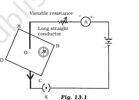
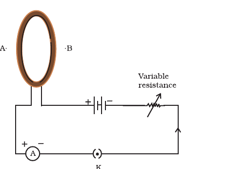
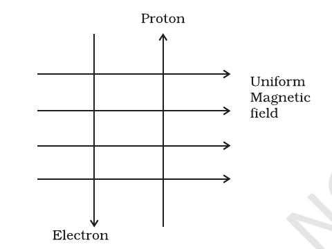
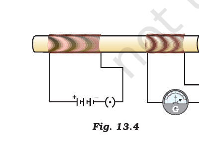
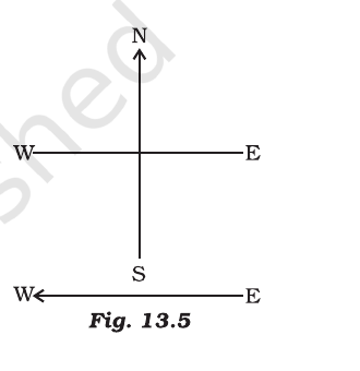
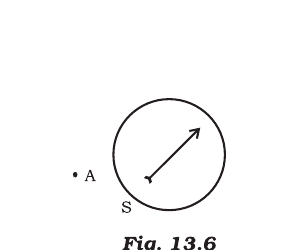
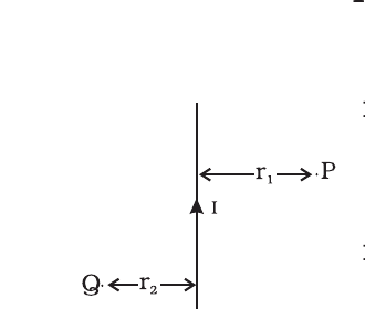


Comments